| Type |
RAy3-11 |
RAy3-18 |
| Radio |
| Frequency range |
10.7 – 11.7 GHz |
17.700 – 19.700 GHz |
| |
|
Lower |
Upper |
Lower |
Upper |
| |
Sub-band A |
10.695 - 10.989 |
11.199 - 11.491 |
17.700 – 18.209 |
18.710 – 19.219 |
| |
Sub-band B |
10.905 - 11.195 |
11.395 - 11.699 |
18.167 – 18.690 |
19.177 – 19.700 |
| |
Sub-band C |
- |
- |
17.700 – 18.300 |
19.300 – 19.700 |
| Type of duplex traffic |
FDD (Frequency division
duplex)
|
| Speed (each direction) |
4.1 – 2026 Mb/s,
see details |
2.8 – 1014 Mb/s, see details;
2.8 – 2026 3) Mb/s,
|
| Channel bandwidth |
5, 7, 10, 14, 20, 28, 30, 40,
56, 60, 80, 100, 112 MHz
|
Sub-bands A, B (ETSI): 5, 7, 7.5, 13.75, 27.5, 55, 110 MHz;
Sub-band C
(FCC): 5, 10, 20, 30, 40, 50, 60, 80, 100, 110 MHz
|
| Dual Channel |
2× 60; 2× 80; 2× 112
MHz
|
up to 2× 110 MHz 3)
|
| Duplex spacing |
typ. 490 MHz (ETSI) or 530
MHz (rest of the world)
|
Sub-bands A, B (ETSI): 1008, 1010 MHz;
Sub-band C (FCC): 1560
MHz
|
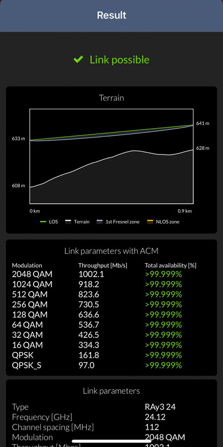
| Modulations |
QPSK, 16QAM, 32QAM, 64QAM,
128QAM, 256QAM, 512QAM, 1024QAM, 2048QAM, 4096QAM
|
| ACM |
Hitless - through all
modulations including stronger FEC 1) |
| Asymmetry of TX/RX
speeds
|
Yes (all combinations of
available Bandwidths 3) &
Modulations supported)
|
| FEC |
LDPC |
| Sensitivity, BER
10-6 |
-100.5 dBm (4.1 Mb/s)
-51 dBm (2026 Mb/s)
see details
|
-101.5 dBm (2.8 Mb/s)
-49.5 dBm (1014 Mb/s)
see details
|
| RF Output Power
(all
modulations)
|
-1 to +24 dBm (7 - 112 MHz channels)
-1 to +23 dBm (5 MHz
channel)
-1 to +18 dBm (Dual channels)
|
-1 to +23 dBm (all channels)
|
| ATPC |
Yes (range 24 dB) |
| Ethernet (user data & management)
|
| RJ45 |
1 Gb Eth. 10/100/1000BASE-T Auto MDI/MDIX
|
SFP
(user
exchangeable)
|
2.5 Gb Eth. SFP slot 10/100/1000/2500BASE-T; 1000BASE-SX; 1000BASE-LX (power max.
1.3 W)
|
| Latency L2 (RFC 2544, one
way)
|
150 μs (66 B / 352 Mb/s); <200 μs (1518 B / 352 Mb/s);
<100 μs
(66 B / 1014 Mb/s); <150 μs (1518 B / 1014 Mb/s)
|
| MTU (max. packet
length)
|
10240 Bytes |
| Synchronization |
Synchronous
Ethernet; PTP (transparent for IEEE-1588v2)
|
| Electrical |
| Primary power |
PoE active IEEE 802.3bt
(POE++)
PoE passive 37 – 60 VDC
DC 37 – 60
VDC
floating
|
| Power consumption
(typ.)
|
30 W for TX ≤ +17
dBm
up to 33 W for TX = +23 dBm
max. 35 W (with SFP)
|
| System interfaces |
| USB |
USB 2.0, Host A;
USB / WiFi; USB / ETH
|
| RSS voltage |
Two contact
sockets
|
| Indication LED |
System status
(multicolor)
|
| System button |
Default settings,
Configuration restore from internal backup
|
| Environmental |
| Ingress Protection |
IP66 |
| MTBF (Mean Time Between
Failure)
|
> 1.000.000 hours
(> 114 years)
|
| Operating temperature |
-30 to +55 °C
(ETSI EN 300019-1-4, class 4.1.)
|
| Operating humidity |
15 – 100 % |
| Surge immunity |
4 kV (EN
61000-4-5)
|
| ESD resistance |
8 kV (EN
61000-4-2)
|
| Mechanical |
| Design & Mounting |
FOD (Full
Outdoor), direct mounting to antenna
|
| Casing |
Rugged die-cast
aluminum, compatible with RAy1 and RAy2
|
| Size |
H×W×D: 160×245×245
mm (6.3×9.6×9.6 in)
|
| Weight |
2.9 kg (6.4 lbs) |
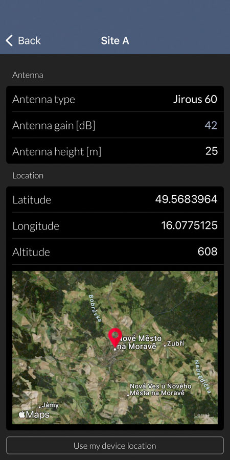
| Antenna |
Class 3, 0.3 – 1.8
m, direct mounting (Jirous or LEAX/Arkivator or Shenglu or others)
|
| Diagnostics & Monitoring |
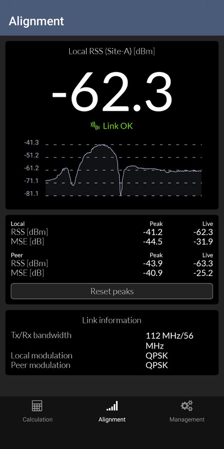
| Real time monitoring |
RSS, MSE,
BER
|
| Diagnostic tools |
Spectrum analyzer,
Pinger
|
| History charts |
Temperature, Power
voltage, RSS, MSE, BER, Data rate, RF Output power
|
| Statistics |
RMON counters for
all interfaces
|
| Antenna alignment |
RSS voltage,
Smartphone app (RAyTools), Web
|
| SNMP |
SNMP v2c including
configurable TRAPs
|
| Security |
| Management |
Web (HTTP, HTTPS),
CLI (SSH, Telnet), Smartphone app (RAyTools)
|
| Access accounts |
3 levels (Guest,
Admin, Super)
|
| WiFi |
passphrase; HW/SW
enable/disable; active only during air-link loss
|
| Encryption |
AES 128, 192, 256
2) |
| Standards |
| Approvals |
CE (RED), RoHS, FCC , IC |
CE (RED), RoHS, FCC,
IC
|