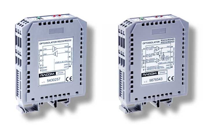
OPI serve for galvanically isolating RS232 interface signal conductors (OPI200), or for converting RS232 interface signals to RS422 or RS232 to RS485 (OPI400) as well as galvanically isolating them.
Galvanic isolation of the interfaces of all MORSE system components, or other devices
Interface conversion RS232 to RS422, or RS485
Profibus
The design and construction of this device allows for long-term loading and for this reason it is primarily determined for continuously running applications.
Profibus compatible
Supply voltage 5-30 V
Protection against reversing of supply voltage polarity
Protection of data lines against over-voltage
Indication LED for data conductors
Indication LED for supply voltage
Speed up to 250 kbps
Switching the direction of communication on the RS485 line done automatically or with an external signal with an arbitrary polarity
Termination (TERMINATE) and definition of the idle state of the RS485 line done (BIAS) with internal switches
Minimum dimensions, mounted on a DIN rail
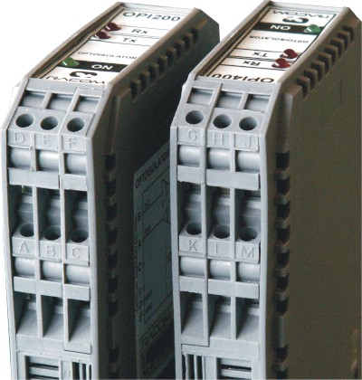
OPI200 provide for a galvanically isolated conversion of RS232/RS232 interfaces. They do not contain any internal switches and they are simple to connect using the instructions on the case.
OPI400 provide for a galvanically isolated conversion of RS232/RS422 or RS485 interfaces.
The type of conversion can be selected using the switch inside the case, after having removed the side panel.
n the case of the RS232/RS485 option it is also possible to choose the following using the switches:
terminate the RS485 line with a 180R resistor (recommended for long transmission lines)
set up the idle state of the RS485 line (recommended for environment with interference)
polarity of the external signal for Rx – Tx switching
optimum speed for automatic Rx – Tx switching, see the table of technical parameters
If an external signal is not applied for Rx – Tx switching OPI400 automatically induces switching from incoming data. If the transfer speed is equal to the speed set using the switches the switching time for switching from the Tx state to Rx is about 2 bytes. If the transfer speed does not match the speeds set in the switches it is necessary to set the switches to the nearest lowest option and count on a proportionately longer Tx – Rx switching time.
Received and transmitted data is indicated by LED’s for all available convertor options. In the case of short data packets the duration the LED’s are lit for is prolonged by approx. 20 ms. A permanently lit LED on data interfaces indicates the presence of a signal with active polarity, i.e. error state during installation.
| setting up OPI400 switches: |
|
| configuration MR400: | in menu set |
| setting up OPI400 switches: |
|