Dual-RAy configuration allows two RAy units to operate on a single antenna in order to increase the capacity of the link above 360 Mbps (current limit of RAy2) or to reach wireless link redundancy. Signal polarization using an OMT (Orthomode transducer) is used to differentiate between signals from each RAy unit, thus both polarizations are used.
RAy-10 (10 GHz band), RAy-11 (11 GHz band) and RAy-18 (18 GHz band) units, which all operate in single polarization. All sub-bands in each of those 3 bands are supported.
OMT is not applicable to RAy-17 (17 GHz band) or RAy-24 (24 GHz band).
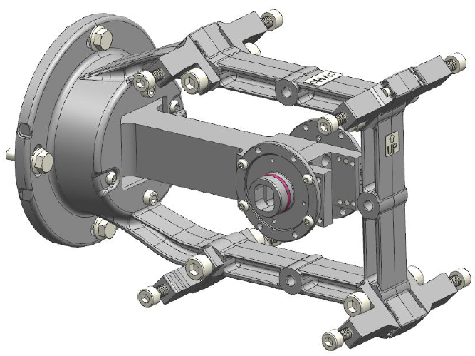
Any standard LEAX-Arkivator or LEAX-RAy antenna can be used for mounting OMT (Orthomode transducer) extension to it – for more details see the manual.
Ordering codes (RACOM part numbers) for all supported bands are listed below:
| Band | RAy | Antenna | OMT |
|---|---|---|---|
| 10 GHz | RAy2-10 | ANT-LEAX-RAy-xxx-10/11* | ANT-LEAX-RAy-OMT-10/11** |
| 11 GHz | RAy2-11 | ||
| 18 GHz | RAy2-18 | ANT-LEAX-RAy-xxx-17/18* | ANT-LEAX-RAy-OMT-18*** |
* xxx means diameter of the antenna (300, 600, 900, 1200)
** Older part numbers: SET-RAY10/11-OMT-LEAX, SET-RAY11-OMT-LEAX
*** Older part number: SET-RAY18-OMT-LEAX
See Dual-RAy + OMT installation manual at download section of RACOM web for RAy microwave unit.
| Important | |
|---|---|
Exact vertical adjustment is crucial if both RAy links will operate on the same channel. Difference in vertical positioning across OMTs negatively influences SNR. This reduces modulation and resultant maximum capacity of each link. |
All combinations of frequencies are supported. The total signal level drop due to OMT use is below 0.5 dBm (in most cases it means negligible).
If different frequencies (different channels) are used for each link (each RAy pair on common OMT):
Transmissions do not interfere with each other and each wireless link operates independently. Each link (each RAy pair on the same polarization) should be configured to its best settings.
Both links are able to reach their maximum performance. This configuration offers the same capacity, distance and availability as 2 standard RAy links operating without an OMT.
If both links operate on identical frequencies (i.e. channels which partially or fully overlap), technical limitations of the installed equipment are experienced. To reach best results:
All RAy units should have Tx power set ensuring that RSS on both receivers on an OMT is the same (i.e. within 0.5 dBm).
ATPC should be switched off (to ensure constant Tx power and RSS).
Link Distances are limited: cross-signaling between both polarization increases with longer distances.
Each RAy must be powered, grounded and protected against surges in the same way as a standard single unit. For details consult RAy manual – Quick Guide and for more detailed information about grounding.
| Note | |
|---|---|
The easiest way for powering RAy units is to use switches or routers with PoE output and supply both RAy units through Ethernet cables. For most installations PoE norm IEEE 802.3at is enough (it guarantees 25.5 W for RAy unit in worst conditions). Each RAy consumes max 21-29 W (see RAy manual). In real operation typically 18-25 W. |
Several settings can be configured above Dual-RAy setup. Two most typical are:
1+1 configuration (redundancy of both links to improve MTBF and partially increase link resistance against interference and noise) is easy to configure with any Eth switch and several protocols are available. If the primary RAy link fails, the secondary link is used to continue the traffic flow.
2+0 configuration (merging the throughput of both links into one logical data stream) requires properly configured Eth switch or router to be present on both ends of the Dual-RAy link. Those must be configured dividing a data stream into 2 portions and merging it again at the other end of the link.
| Note | |
|---|---|
|
Important condition is that internal throughput of the switch/router equipment has to be adequate to serve Dual-RAy configuration. Please consult RACOM Technical Support if you need to verify capability of chosen switch / router for your case.
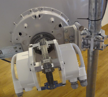
RACOM has field tested the cross-polarized link over a 1.4 km distance (with clear Fresnel zone) using the following configurations:
2× 0.6 m antennas (ANT-LEAX-RAy-600-10/11)
2× OMT extenders (ANT-LEAX-RAy-OMT-10/11)
4× RAy2-11 units for sub-band B (2× RAy2-11-LB + 2× RAy2-11-UB)
or 4× RAy2-10 units for sub-band A (2× RAy2-10-LA + 2× RAy2-10-UA)
2× Cisco switches SG200-8
or 2× Mikrotik routers RB750Gr3, RB3011, CCR1009
Non-identical frequencies (different channels) results:
Tests confirmed that both links on OMT operate 100 % independently from each other
Total capacity 720 Mbps was reached (for link where single RAy would reach 360 Mbps, i.e. on 56 MHz channel and 256 QAM)
All radio configuration parameters (channel widths, QAMs, ACM, ATPC and other settings) functioned as expected.
All channel combinations between links (including neighbor channels) works perfectly
Identical frequencies (same channels) results:
Total capacity was 608 Mbps for most of the test (operated on 56 MHz channel and 128 QAM, i.e. 304 Mbps per link)
Total capacity was never worse than 514 Mbps (56 MHz, 64 QAM, i.e. 257 Mbps per link)
Modulation was never worse than 64 QAM and never better than 128 QAM (due to actual SNR)
Please consult RACOM Technical Support for more details and recommendation.