The RAy10 microwave bridge is designed for operation in backbone networks for transmission in the licence-free 10 GHz band.
It works as a point-to-point bridge in full duplex mode with a signalling rate of up to 170 MBps. The bandwidth is optional, namely 28/14/7 MHz. Modulation can be set to be fixed or adaptive in the range QPSK to 256-QAM.
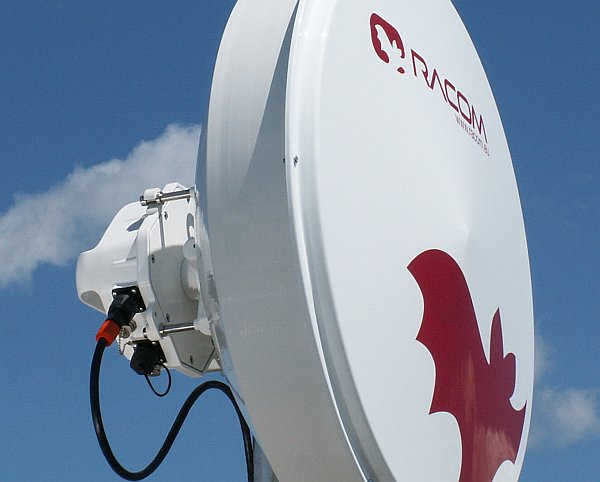
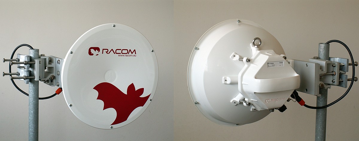
The link is formed by two stations of FOD (Full Outdoor) design. One of them is labelled RAy10-LB and transmits in the lower half of the frequency band, and the second is labelled RAy10-UB and transmits in the upper half of the band (or RAy10-LB-2 and RAy10-UB-2 – see Section 3.2, “Installation”).
The line can be assembled with several types of antennas.
| eth connectors | microwave band | standard | |||
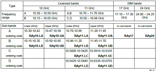
| RAy10-LA | + | RAy10-UA | common | 10.3 – 10.6 GHz | Czech |
| RAy10-LA-2 | + | RAy10-UA-2 | separated | 10.3 – 10.6 GHz | Czech |
| RAy10-LB | + | RAy10-UB | common | 10.15 – 10.65 GHz | Europe |
| RAy10-LB-2 | + | RAy10-UB-2 | separated | 10.15 – 10.65 GHz | Europe |
Detailed frequency table see Section 9.2.4, “Nominal frequencies RAy10-xB, duplex 350 MHz”.
Antenna is attached to a mast tube with an adjustable mounting rack. A RAy unit is then mounted onto the antenna. Two assembly positions are possible – either for horizontal or vertical polarization. The rack installation and setting up is described in the Antenna mounting chapter.
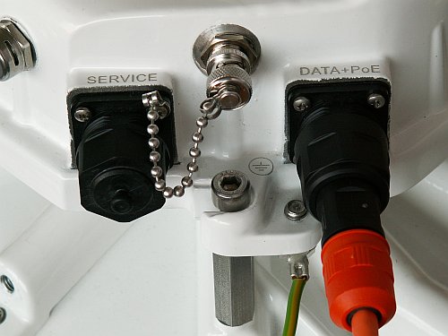
Connection to LAN may use one or two connectors:
RAy10-LB RAy10-UB uses a shared connector for user data, service access and PoE power supply
RAy10-LB-2, RAy10-UB-2 uses two connectors, one for user data and PoE power supply, and one for service access. Connector setup is described in the Connectors chapter.
A third BNC connector enables connecting a voltmeter for RSS indication during setup.
Basic technical parameters are stated in Chapter 9, Technical parameters.
| Communication unit ODU | Outer size | 245 x 245 x 150 mm | ||||||||||
| Weight | RAy10 | 2.9 kg | ||||||||||
| Diameters of supplied antennas | Jirous | Arkivator | ||||||||||
| RAy10 |
|
| ||||||||||
| Mast diameter at point of link holder fixing | ø40 – ø115 mm | |||||||||||
| Distance of antenna axis from mast axis | cca 270 mm | |||||||||||
| The antenna dimension drawings can be found in: | Appendix A, Antenna dimensions | |||||||||||
| Technical data can be found at www.racom.eu: | RAy10 | |||||||||||
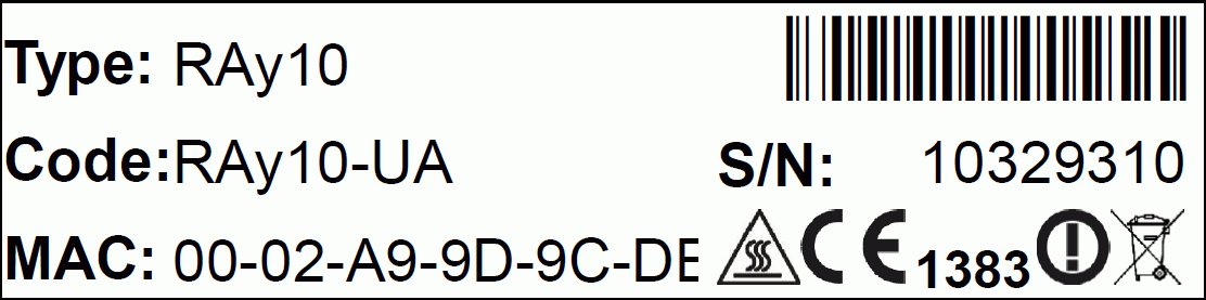
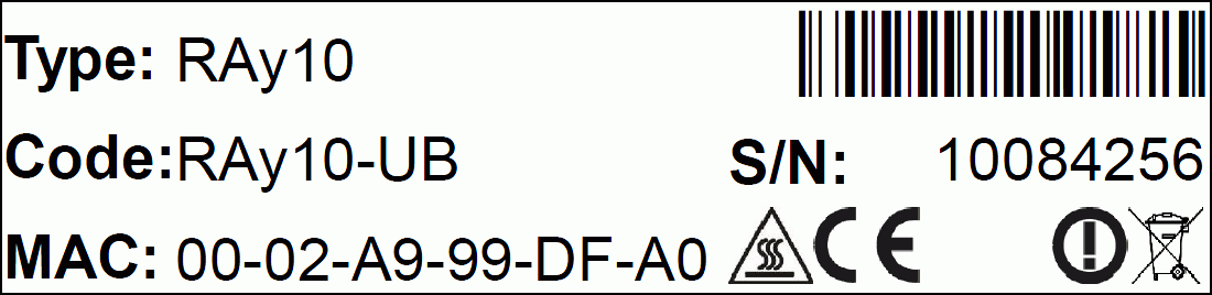
Name plate
The plate contains name, bar code record, CE label, etc.:
Type – RAy product line identification
Code – detailed identification of the station type (for details see Section 3.5, “Ordering codes”)
S/N – serial number, link contains stations with two different numbers
MAC – HW address of user ethernet port
The proper pair of Lower and Upper units should be selected when
ordering the microwave link. This is not true for ISM bands units
(RAy17, RAy24). In such a case the same unit is used for both sides of
the link.
Note – The
Lower and Upper unit has to be selected from the same sub-band (i.e.
from the same row of the table).
The RAy11, RAy17 and RAy24 ordering codes are stated here for clarity. Their User manual can be found here.
In case of the two-port units, the “-2” label shall be connected to the end of the ordering code. Example:
RAy10-LA-2
RAy10-UB
The Feature keys ordering code consists of three parts:
XXX-YYY-ZZZ
XXX
-product type, e.g. “RAy10”.
YYY
– Feature key type.
Key
to permit the user maximum speed is marked SW, value in Mbps
The
key to increased transmission power is labeled PWR, value
in dBm
ZZZ –
Feature key value, example:
RAy10-SW-170 … RAy10 user data speed enabled on the maximum value 170 Mbps.
RAy10-PWR-10 … Increasing the maximum transmission power for RAy10 from 3 dBm to 10 dBm.
The microwave bridge comes supplied as standard with:
two FOD units
tub of NOVATO silicon lubricant (mixture of silicon grease, PTFE and other additives) for lubricating the antenna pin (see Section 5.2.3, “Lubrication and preservation of the antenna pivot”).
Microwave bridge accessories need to be ordered separately, for further details please see www.racom.eu
Two pieces of parabolic antennas with mast holder – according to user needs and specifications.
The antenna from two different vendors are available currently (year 2013). The overview of different antenna types is listed in paragraph Dimensions. The antenna choice determines radio link properties. The radio link calculation should be performed to determine proper antenna size. Rough calculation can be done using simple on-line calculator.
The other antenna producers can be used with RAy links as well. The RAy unit can be attached to the antenna by flexible waveguide or directly by means of special interconnetion part. There are several types of those parts for Andrew and Arkivator antennas. It is possible to develop the interconnetion part also for other antenna types.FOD unit power supplies – 30W PoE adapters
two connectors (plastic IE-PS-V01P-RJ45-FH or metallic IE-PS-V01M-RJ45-FH) for connecting the FOD unit for outdoor use – these quality connectors allow the connection of cables with conductors of cross-sectional area 0.129–0.329 mm2 (AWG 26 – AWG 22, i.e. ø0.4–ø0.64 mm). For assembly instructions see chapter Section 5.3.2, “Fitting an external IE-PS-V01P-RJ45-FH connector”
two IE-PS-RJ45-BK connectors for connecting the FOD unit for indoor use.
S/FTP Cat.7 cable for connecting FOD units to the network.
AGC cable for connecting a voltmeter to the RAy unit for adjusting the antenna direction. (see “Antenna mounting”, point g – g)
Grounding set for grounding the CAT7 cable. Manufactured by PEWTRONIC s.r.o., code S/FTP 4+2
RAy grounding set for grounding RAy equipment to the mast. Contains a ZSA16 grounding terminal, grounding tape and a cable with grounding lugs.
Grounding set for grounding the CAT7 cable, RAy grounding set – see images Fig. 5.61 – “Grounding kit for S/FTP 4+2 cable” and Fig. 5.63 – “RAy grounding kit”.
Additional microwave bridge accessories which have been specially selected for installation of RAy microwave bridges can also be ordered :