https//www.racom.eu/eng/products/m/ray2/index.html


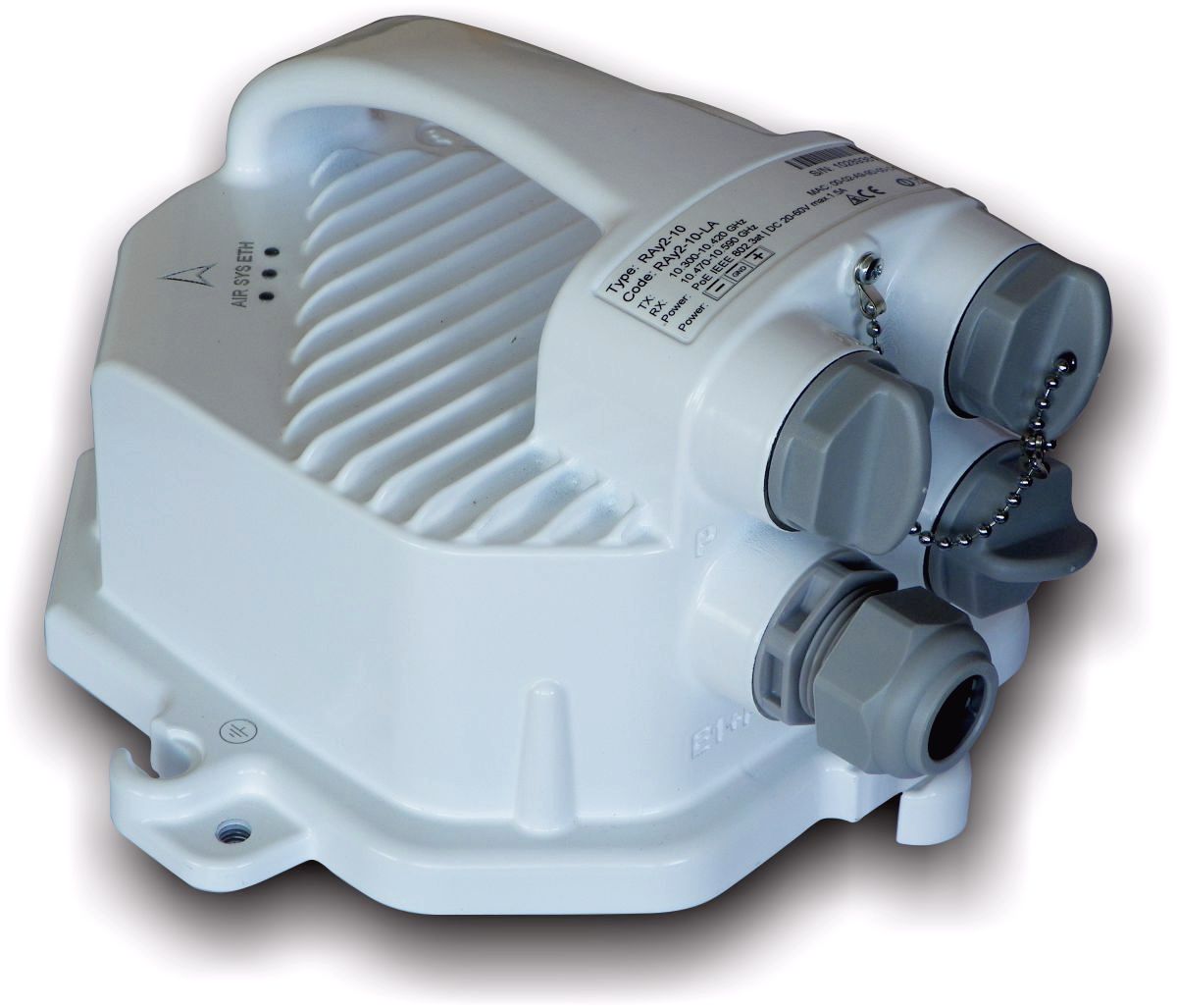
Table of Contents
- Legal Notice
- Quick guide
- List of documentation
- 1. Product
- 2. Accessories
- 3. Step-by-step Guide
- 4. Installation
- 5. Configuration
- 6. Command Line Interface
- 7. RAy Tools app for Mobile devices
- 8. Troubleshooting
- 9. Technical parameters
- 10. Safety, regulations, warranty
- 10.1. Regulations
- 10.2. Important Notice
- 10.3. Safety distance
- 10.4. Professional installation
- 10.5. RoHS and WEEE compliance
- 10.6. Liability for Defects and Safety Instructions
- 10.7. Important Notifications
- 10.8. Warranty
- 10.9. EU Declaration of Conformity
- 10.10. FCC authorization of transmitters
- 10.11. Country of Origin Declaration
- A. IP address in the PC (Windows XP)
- B. IP address in the PC (Windows 7)
- C. IP address in the PC (Windows 8)
- D. SSH key generation
- E. Https certificate
- F. Unit block diagrams
- Index
- Revision History
List of Figures
- 1.1. RAy2 – Microwave link
- 1.2. Waveguide pivot and flange
- 1.3. Antenna pivot with O-ring and RAy waveguide flange
- 1.4. RAy2 Microwave link – antenna and RAy unit
- 1.5. Grounding screw
- 1.6. Pressure equalization screw
- 1.7. Connectors
- 1.8. RJ45 Ethernet connector
- 1.9. SFP slot
- 1.10. Power supply connector
- 1.11. USB connector
- 1.12. USB WiFi adapter
- 1.13. Ethernet adapter
- 1.14. RSS voltage contacts
- 1.15. Hardware button
- 1.16. Status LEDs ( AIR – SYS – ETH )
- 1.17. Example of production label – RAy2-18
- 1.18. Example of production label – RAy2-24
- 1.19. Packaging of both units
- 1.20. SILICONE GREASE capsule
- 3.1. Link Configuration (RAy2-17, perpendicular holders)
- 3.2. Configuration Menu Link settings – General
- 3.3. Configuration menu Link settings – Service access – Services
- 3.4. Configuration menu Link settings – Service access – Users
- 4.1. Fresnel zone
- 4.2. Flexible waveguide assembly
- 4.3. OMT interface plate
- 4.4. Mounting example
- 4.5. Grease points on the antenna pivot and RAy unit flange
- 4.6. SILICONE GREASE capsule
- 4.7. Horizontal RX polarization – see the arrow sign
- 4.8. Vertical RX polarization – see the arrow sign
- 4.9. Right-side mounting – vertical RX polarization
- 4.10. Right-side mounting – horizontal RX polarization
- 4.11. Protective conductor at the RAy unit
- 4.12. Grounding the RAy unit
- 4.13. RAy grounding kit
- 4.14. Protective conductor at the mast on a ZSA16 terminal
- 4.15. RAy2 connectors
- 4.16. Bushing assembly for metallic Ethernet with short ETH connector
- 4.17. Bushing assembly for metallic Ethernet with long ETH connector (or for non-OFA fibre optic cable)
- 4.18. Bushing assembly for optical Ethernet (with RACOM / OFA fibre optic cable)
- 4.19. Old-style bushing including 35 mm metallic lengthening
- 4.20. Bushing including long lengthening
- 4.21. Grounding installation 1
- 4.22. Grounding installation 2
- 4.23. Grounding kit universal for 5-11mm cables
- 4.24. Grounding kit for S/FTP 4+2 cable
- 4.25. Grounding kit detail
- 4.26. Separated lightning conductor
- 4.27. Example of a correct lead installation.
- 4.28. Grounding options
- 4.29. Antenna lobe diagram
- 4.30. Signal strength graph
- 4.31. Correct alignment diagram
- 4.32. Radiation diagrams
- 4.33. Radiation diagram – incorrect adjustment
- 4.34. 3D example of more complicated Radiation Pattern
- 5.1. Info Refresh
- 5.2. Login
- 5.3. Status bar 1
- 5.4. Status bar 2
- 5.5. Page example
- 5.6. Menu Status
- 5.7. Menu Link settings / General
- 5.8. Menu Link settings / Radio
- 5.9. Menu Link settings / Service access / Services
- 5.10. Menu Link settings / Service access / USB accessories
- 5.11. Menu Link settings / Service access / Users
- 5.12. Menu Link settings / Service access / Users / edit
- 5.13. Menu Link settings / Alarms / Status
- 5.14. Alarm severity
- 5.15. Menu Link settings / Alarms / Acknowledge
- 5.16. Menu Link settings / Alarms / Config
- 5.17. Menu Switch settings / Port status
- 5.18. Menu Switch settings / RMON counters
- 5.19. Menu Switch settings / Queue allocation
- 5.20. Menu Switch settings / Register dump
- 5.21. Menu Switch settings / RSTP
- 5.22. Menu Switch settings / Port
- 5.23. Menu Switch settings / Port advanced
- 5.24. PIRL and queues
- 5.25. Menu Switch settings / PIRL
- 5.26. Leaky bucket
- 5.27. Menu Switch settings / PIRL Resource
- 5.28. Menu Switch settings / Egress queue
- 5.29. Menu Switch settings/QoS/802.1p
- 5.30. Menu Switch settings /QoS/DSCP
- 5.31. Advanced menu diagram
- 5.32. Menu Switch settings / Advanced / VLAN
- 5.33. Menu Switch settings / Advanced / STU
- 5.34. Menu Switch settings / Advanced / STU / edit
- 5.35. Menu Switch settings / Advanced / VTU
- 5.36. Menu Switch settings / Advanced / VTU / edit
- 5.37. Menu Switch settings / Advanced / ATU settings
- 5.38. Menu Switch settings / Advanced / ATU
- 5.39. Menu Switch settings / Advanced / ATU / edit
- 5.40. Menu Switch settings / Advanced / Monitoring, Policy
- 5.41. Menu Switch settings / Advanced / RSTP
- 5.42. Menu Switch settings / Advanced / Trunk
- 5.43. Menu Tools / Backup
- 5.44. Menu Tools / Maintenance / Feature keys
- 5.45. Menu Tools / Firmware
- 5.46. Menu Tools / Radio adaptation
- 5.47. Menu Tools / Restart
- 5.48. Menu Tools / Bar indicators
- 5.49. Ray Tools
- 5.50. Menu Tools / RX constellation
- 5.51. Menu Tools / Frequency analyzer
- 5.52. Menu Tools / History / Thumbnails
- 5.53. Menu Tools / History / Viewer
- 5.54. Menu Tools / History / Data
- 5.55. Menu Tools / Logs
- 5.56. Menu Tools / Programs / Ping
- 5.57. Menu Tools / Programs / CLI
- 5.58. Help menu
- 5.59. Parameter help
- 5.60. Configuration menu help
- 5.61. Summary help
- 6.1. CLI menu
- 10.1. EU Declaration of Conformity RoHS, WEEE
- 10.2. EU Declaration of Conformity for RAy2-10
- 10.3. EU Declaration of Conformity for RAy2-11, RAy2-18
- 10.4. EU Declaration of Conformity for RAy2-17, RAy2-24
- 10.5. RoHS and WEEE Declaration of Conformity for RAy
- 10.6. Country of Origin Declaration
- F.1. Block diagram of the unit
- F.2. Switch and connected ports
List of Tables
- 1.1. Meaning of LED status indicators
- 1.2. Overview of Jirous Class 2 and Class 3 antennas
- 1.3. Overview of LEAX-RAy antennas
- 1.4. Overview of Shenglu-RAy antennas
- 1.5. Capacity keys code scheme
- 1.6. Upgrade keys code scheme
- 10.1. Minimum Safety Distance 11 GHz
- 10.2. Minimum Safety Distance 18 GHz
- 10.3. Minimum Safety Distance 24 GHz