The following chapters will guide you step by step through preparation, installation and activation of the RAy2 link:
Pre-installation check out
Installation (Chapter 4.)
Advanced configuration (Chapter 5.)
Troubleshooting (Chapter 8.)
Pre-installation Checklist
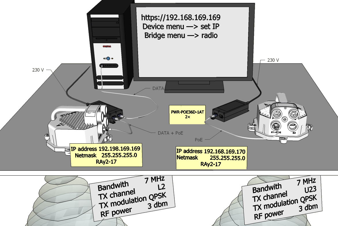
Familiarise yourself with the controls and prepare your configuration ahead of the installation of the link on the mast tube.
Both units (without antennas) can lie on a desk with flanges running
parallel and facing up at an angle; on a non-metal desk they can also face
downward.
– In the case of units RAy2-17 and RAy2-24
turn the unit holders so that they are roughly perpendicular to each other
and set higher power, about 3 dBm. Before installation return power to a
minimum.
– In the case of units operating in licensed bands
(RAy2-10, RAy2-11, RAy2-18), turn unit
holders so that they are roughly parallel to each other. Use an ethernet
cable to connect each of the units to a PoE source and connect a PC to one
of them for configuration.
Take the following steps to establish a connection between the PC and RAy2 and perform a basic setup.
WARNING: During operation, never bring the waveguides of the stations close to each other. There is a risk of damaging sensitive input circuits.
The RAy2 link is supplied with a default configuration of access parameters:
For Ethernet access through RJ45 or SFP ports:
Unit L has the service IP address 192.168.169.169 and mask 255.255.255.0
Unit U has the service IP address 192.168.169.170 and mask 255.255.255.0
For WiFi or Ethernet access via USB/WiFi or USB/Eth adapter:
Both units have service IP address 172.17.17.17 and mask 255.255.255.0
For Ethernet access through RJ45 or SFP ports an IP address has to be set on your PC that is within the mask, e.g. 192.168.169.180. For WiFi or USB/Eth access an IP address for laptop or mobile or tablet is set automatically by DHCP (enabled by default).
Then open the http or https configuration interface, e.g. https://192.168.169.169 or
http://172.17.17.17
Access is allowed over HTTP, HTTPS or SSH.
The
default username is “admin” and the password is also “admin” (it is strongly recommended to
change it).
See Configuration / Link settings / Service access / USB accessories chapter for detailed information.
The Antenna Alignment Tool can also be used for antenna direction
alignment accessed via a web browser utilising IP addresses of the unit
with „/tk“ at the end (e.g. http://192.168.169.169/tk or
http://172.17.17.17/tk
).
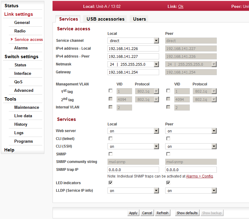
When connection has been established, use the Service access menu to customize access parameters.
Default management IP addresses should be replaced with well-chosen operating addresses. Default can lead to network problems later.
The menu contains parameters for the entire link, both for the Local and remote Peer units. If a connection has been established, both sets of parameters have been set. While working with an isolated unit, only Local parameters are functional for the currently connected unit.
| Note | |
|---|---|
If the link is OK and there are no parameters shown of the station Peer, it is necessary to click on . |
Follows the description of basic settings. After entering values on the screen always save the content by clicking on .
| Note | |
|---|---|
If there is any problem with https certificate after completing the firmware upgrade, please see the Annex Https certificate for further steps. |
Station name – station can be assigned with a name, e.g. the place of installation.
Station location – for easier inclusion the network hierarchy, it is possible to enter the station’s location
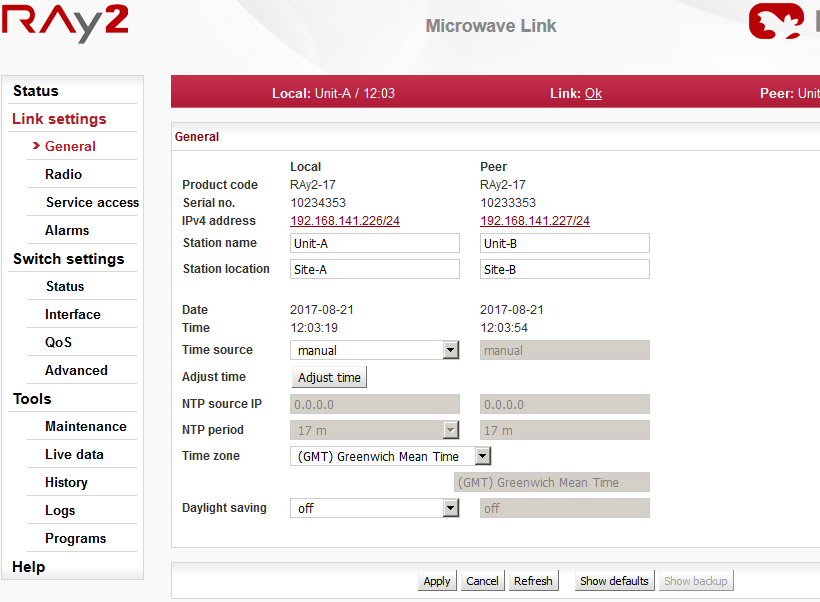
IPv4 address – enter a valid IP address to access the unit. The default IP address has to be replaced with a valid address. Keeping the default address will probably lead to future problems in the network.
Netmask – enter the network mask.
Gateway – if necessary, enter a gateway, otherwise leave blank
Enable access protocols that you are going to need. For security reasons, do not enable more than is necessary.
HTTP(S) – allow access to the web interface.
Telnet – enabling access to the CLI interface using telnet protocol.
SSH – enabling access to the CLI interface using SSH protocol.
Management VLAN – Enabling 802.1Q VLAN tag for separation of user and service operations.
Management VLAN ID – Defining 802.1Q VLAN tag for service operations.
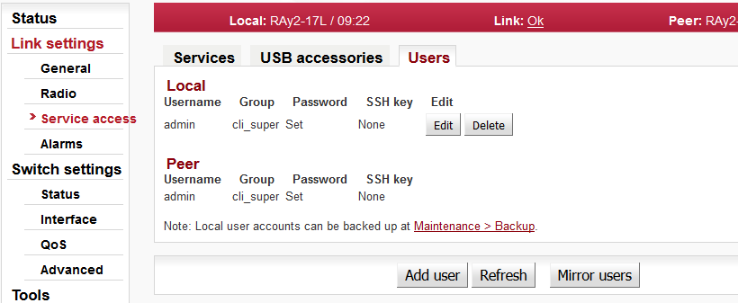
Edit – enter the menu.
New password – choose a password and enter it.
Confirm password – enter the password again to confirm.
The firmware of the microwave link is capable of controlling the maximum user data speed. The default user speed without the feature key is the minimum for the respective hardware unit. The feature key to assign the maximum user data speed, should be installed prior to physical installation. For further details see Section 5.6.1.2, “Feature keys” .
Default radio parameters depend on the specific type of link and the specific channel allocation table. Channels are typically set in the lower part of the band, the smallest bandwidth, QPSK modulation, and low power. Both units in the pair should be capable of immediate communication. If it is possible to work with these radio parameters at the installation location, the link can be activated. On an operating link the required operating parameters can then be set up.
If a change in the parameters is necessary, it is done in the menu Link settings / Radio and saved by clicking Apply. This applies when working on both units simultaneously if they are connected, otherwise each unit is configured individually. When configuring units individually, pay attention to correct settings of duplex pair for channels TX and RX. For example, if one station has TX channel L1, then the second station must also have the channel RX L1.
Verify the functionality of the radio link:
Switch in screen Status / Brief.
Status Bar displays Link: Ok.
If the alarm message appears at Local or Peer, this doesn’t necessarily mean there is a problem. The message indicates that the limit at any of the monitored parameters has been exceeded. Essential is the “Link: Ok” message on the status bar.The Status screen contains values for both Local and Peer units. N/A next to Peer indicates that the data from the Peer unit has not been transferred. If Link is Ok, simply click Refresh at the bottom of the screen and Peer data will be updated.
Menu Status / Detailed / Radio indicates link RSS and SNR values, in case of ACM also the selected modulation and Netbitrate. If the ATPC function is enabled (menu Link settings / Radio) it also indicates instantaneous / max. allowed power and for SNR and RSS values it indicates immediate / target value size.
Menu Tools / Live data / Bar indicators displays current size of RSS, SNR and BER.
Menu Tools / Programs / Ping allows you to send a ping test to the selected IP address.
Try out the possibility of modulation:
Modulation ACM. In menu Link settings / Radio enable ACM. Set the TX modulation parameter to the required maximum value. In menu Status / Brief / Radio you can monitor (Refresh or Start) changes in used modulation based on the instantaneous SNR signal quality. The status and quality of modulation is demonstrated well in menu Tools / Live data / RX constellation diagram, hit Refresh.
To set a fixed modulation go to Link settings – Radio, switch off ACM and set the TX modulation to a value from the range of QPSK through 256-QAM based on the results of the previous test. If you choose modulation higher than allowed by SNR, the connection will be lost. Status Link will lose its Ok value. Both units will need to be moved closer to resume the link. If this is not possible, use the ethernet to access each unit individually and set the basic modulation QPSK. You can monitor the quality of the received signal under Tools / Live data / RX constellation diagram.
Verify the functionality of the entire link:
If possible, connect user devices to both RAy2 units over PoE and test mutual communication.
Another way of testing this is to connect a PC to the other unit and send a ping from one PC to the other.
The minimum variant of this test is to use an ethernet cable connection from the PC connected to the local RAy2 to the PC connected to the remote RAy2 and test communication between both units over ethernet. This will verify ethernet functionality.
Prepare installation configuration:
Bandwidth e.g. 3.5 MHz. To get the highest possible receiver sensitivity, set the bandwidth as narrow as possible according to specific frequency band.
TX channel: Use your allocated channel. If you do not have allocated channel yet, use for example channel L1.
RX channel will setup automatically when channel lock activates.
Set TX modulation QPSK to get the highest possible sensitivity.
Set RF power according to selected antenna and according to individual frequency licence. Set the output power as high as possible.
Set a new users access passwords.
Record the access parameters from the Service access menu, especially the IP addresses.
Restart by interrupting the power supply to verify that the parameters are stored correctly and the link works.
After this preparation phase you can continue to install your devices in a working environment.