This chapter will guide you step by step through the basic link preparation, installation and configuration. A brief description of all those steps in a picture form can be found in Quick guide (the introductory chapter to this manual). Its shortened version is printed on the cardboard holding each delivered unit inside each transport box.
For detailed description of all possible functionality of the unit see other chapters, mainly:
Default settings for L and U units are chosen to allow delivered units to automatically establish a link without unpacking RAy3 units from the box. It is enough to open the boxes and power both RAy units up (by PoE or DC power supplies). It allows users to comfortably set up basic parameters necessary for the installation in the lab and thus shorten the time on the tower or roof to a minimum. Following text provides a guide how to optimally arrange the workplace, how to setup the link and which parameters are good to be set up before the installation outside.
Default factory settings define the initial link to be established on the most narrow channel, strongest modulation and lowest available RF Output power (in RAy3-17 and RAy3-24 case those are 3.5 MHz channel, QPSK_S modulation and TX power = -30 dBm). Complete default settings for all models are described in Chapter 9, Technical parameters.
| Note | |
|---|---|
RAy3 default factory settings allow to install both units on the mast and establish the very short link without prior manual configuration. Typically, TX power has to be increased to a reasonable level (or even to a maximum) before link alignment, because default value of ‘Max TX power’ is too low for the reasonable distance. |
Take the following steps to link together both delivered RAy3 units and to establish a connection between them and PC or tablet or mobile and perform a basic setup:
Open both boxes and double check that both RAy3 units are turned OK, so waveguides are heading to each other.
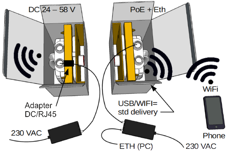
Connect power sources (PoE or DC) to both RAy3 units (using slot ETH1+POE).
Wait about 30 seconds until both units boot up and the link is established. The green light should be visible on both units through transparent plug on slot “S”. Until a WiFi password is set, red light periodically flashes together with green light – see Section 1.5, “Status LED ( S )”.
Connect by WiFi or by Ethernet cable (plugged in to LAN input on PoE power supply or in to Eth port on USB/ETH adapter) to one of those two units. Units linked together allow effectively set all IP addresses, passwords, security keys, SW feature keys, users, etc. from one side of the link.
If WiFi is used, then just select which WiFi to connect to. IP address of your PC or laptop is set automatically by DHCP.
If Eth over USB port is used (through USB/ETH adapter OTH-USB/ETH-XA), IP address of your PC or laptop is set automatically by DHCP as well.
If Eth connection to one of data ports on RAy3 (ETH1 or ETH2) is used, then the IP address on your PC or laptop has to be set manually to establish a working connection. See Quick Guide for the complete list of IP addresses to use.
Enter a web management of the unit and configure everything you like to change to be ready for outside installation. Following parameters are typically set in this phase:
IP addresses and VLANs
passwords
security keys
SW feature keys
users
WiFi password and behavior
TX and RX frequencies (if known in advance)
Higher TX power (to be ready for antenna alignment) – see section “Important” below
| Note | |
|---|---|
|
| Important | |
|---|---|
|
The RAy3 link is supplied with a default configuration of access parameters:
For Ethernet access through RJ45 or SFP ports:
Unit L has the service IP address 192.168.169.169 and mask 255.255.255.0
Unit U has the service IP address 192.168.169.170 and mask 255.255.255.0
For WiFi or Ethernet access via USB/WiFi or USB/ETH adapter:
Both units have service IP address 172.17.17.17 and mask 255.255.255.0
For Ethernet access through RJ45 or SFP ports an IP address has to be set on your PC that is within the mask, e.g. 192.168.169.180. For WiFi or USB/ETH access an IP address for laptop or mobile or tablet is set automatically by DHCP (enabled by default).
Then open the HTTP or HTTPS configuration interface, e.g. https://192.168.169.169 or
http://172.17.17.17
Access is allowed over HTTP, HTTPS or SSH.
The
default username and the password is “admin” (it is strongly recommended to change it).
See Configuration > Link settings > Service access > USB accessories chapter for detailed information.
The Antenna Alignment Web Tool can also be used for antenna direction alignment. It can be accessed via a web browser utilizing IP addresses with „/tk“ at the end (e.g. http://172.17.17.17/tk for WiFi or USB/ETH adapter or http://192.168.169.169/tk or http://192.168.169.168/tk for ETH1/ETH2 ports).
When connection has been established, use the Service access menu to customize access parameters.
Default management IP addresses should be replaced with well-chosen operating addresses. Default can lead to network problems later.
The menu contains parameters for the entire link, both for the Local and remote Peer units. If a connection has been established, both sets of parameters have been set. While working with an isolated unit, only Local parameters are functional for the currently connected unit.
| Note | |
|---|---|
If the link is OK and there are no parameters shown of the station Peer, it is necessary to click on . |
Follow the description of basic settings. Pictures in following sections show default factory settings for 24 GHz L unit and RC info “rcinfo24_ISM250_default:XXX”. Default settings for unit U (for opposite side of the link) would be adequately exchanged. Names of rcinfo file and values each one represents may be different for other RCinfo (differences typically refer to frequencies and TX power as they are allowed by authorities for the actual band and a region).
After entering values on the screen always save the content by clicking on .
Menu Tools > Maintenance > Radio adaptation
First step is to set the right set of rules for the band according the region or country of use, so the unit is compliant with the local regulation. Go to the menu according the picture below and set parameter RCINFO accordingly.
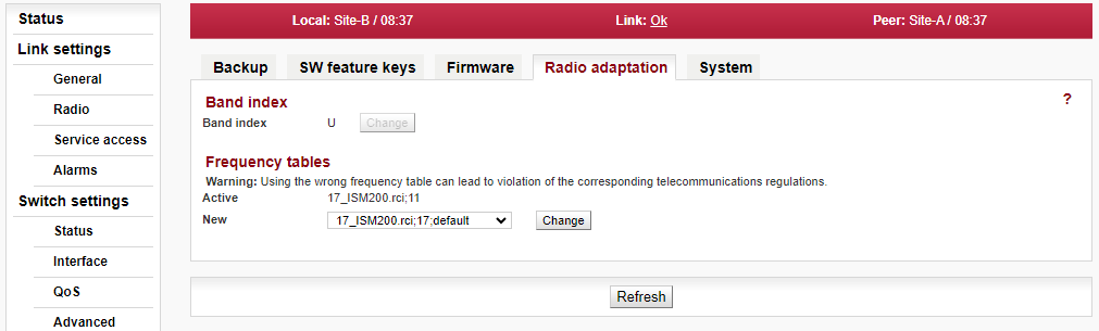
For full explanation of all possibilities of this screen see Section 5.6.1.4, “Radio adaptation” in Chapter 5, Configuration.
Menu Link settings > General
Not necessary settings. Anyhow it is beneficial to name the link and its location for easier identification later on:
Station name – station can be assigned with a name, e.g. the place of installation.
Station location – for easier inclusion the network hierarchy, it is possible to enter the station’s location
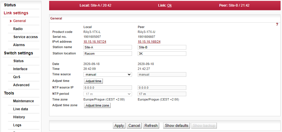
For full explanation of all possibilities of this screen see Section 5.4.1, “General”.
Menu Link > Service access > Services
Those settings are necessary to make new units accessible within target Ethernet network. Typically, all following parameters should be set according to both networks IP addressing, routing, planned access methods for data and for management, etc.:
IPv4 address – enter a valid IP address to access the unit. The default IP address has to be replaced with a valid address. Keeping the default address will probably lead to future problems in the network.
Netmask – enter the network mask.
Gateway – if necessary, enter a gateway, otherwise leave blank.
Enable access protocols that you will need. For security reasons, do not enable more than is necessary.
HTTP(S) – allow access to the web interface.
Telnet – enabling access to the CLI interface using telnet protocol.
SSH – enabling access to the CLI interface using SSH protocol.
Management VLAN – Enabling 802.1Q VLAN tag for separation of user and service operations.
Management VLAN ID – Defining 802.1Q VLAN tag for service operations.
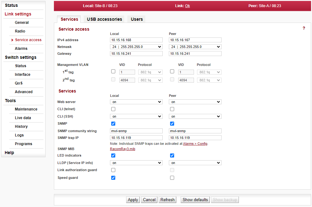
For full explanation of all possibilities of this screen see Section 5.4.3, “Service access” in Chapter 5, Configuration.
Menu Link > Service access > Users
It is recommended to create user accounts managed by the main user already in this phase (for example a user with rights limited to read-only access). Following actions are available:
Edit – enter the menu.
New password – choose a password and enter it.
Confirm password – enter the password again to confirm.
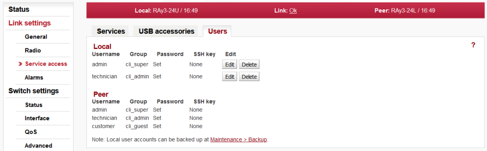
For full explanation of all possibilities of this screen see Section 5.4.3.3, “Users” in Chapter 5, Configuration.
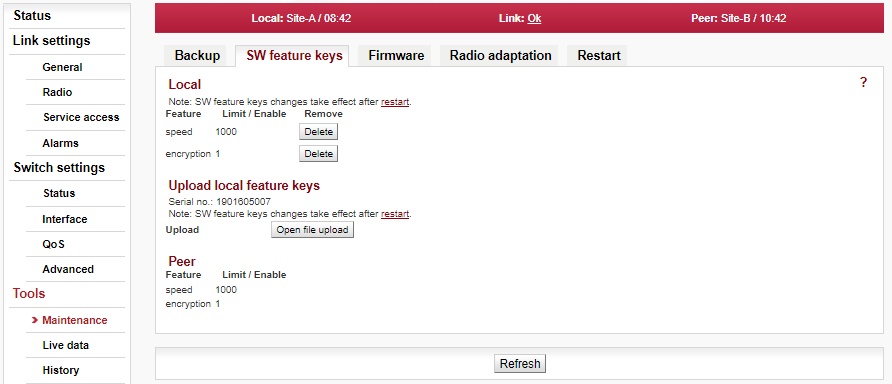
The firmware of the microwave link is capable of controlling several features (for example the maximum user data speed, maximum TX power, etc.). It is recommended to install all separately purchased SW feature keys prior to physical installation to allow all expected functionality of the link to be usable after the installation.
| Note | |
|---|---|
Speed keys purchased with the unit are installed in the factory (and can be double checked within this menu). Key for limited TX power is not installed except specifically ordered. If RCinfo limits the maximum power, it cannot be overruled by SW feature key with the higher TX power. |
For full explanation of possibilities of this screen see Section 5.6.1.2, “SW feature keys” in Chapter 5, Configuration.
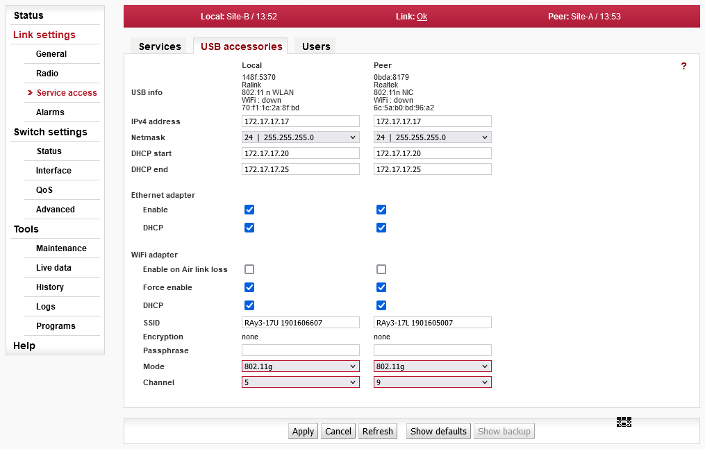
Menu Link > Service access > USB accessories
Go to menu Link Settings > Service Access > USB accessories and enter WiFi password or disable WiFi completely. Standard settings are that Enable on Air link loss is ON (when the link is down, WiFi is activated; when link is OK, WiFi will be deactivated in few minutes) and Force Enable is OFF (activates WiFi permanently). Passphrase has to be set, otherwise the WiFi is unsecured and system warning is active.
| Note | |
|---|---|
If you access the unit over WiFi, do this step as last action before reboot (as the WiFi connection will be interrupted and new connection with new password would be required to continue the work). |
For full explanation of possibilities of this screen see Section 5.4.3.2, “USB accessories” in Chapter 5, Configuration.
Default radio parameters depend on the specific type of link and the specific channel allocation table. Channels are typically set for smallest possible bandwidth in the lower part of the band. Radio defaults also define QPSK modulation (in the case of RAy3-80 default is 2PSK_BW/4_S modulation), the lowest possible ‘Max TX power’ parameter and ATPC off, so both units in the pair should connect each other right from the box (or even inside a box). If there is no spectrum conflict with other equipment in the room (or on sites later on) and units can “hear” each other, those parameters can be used as they are and both units can be powered on. After boot (about 30 seconds) the link should be automatically established.
If a change of the parameters is necessary, it can be done in the menu Link settings > Radio and saved by clicking Apply button. This applies, when the work is done simultaneously on both units, while they are connected. Otherwise each unit has to be configured individually. When configuring units individually, pay attention to correct settings of duplex pair for channels TX (transmission) and RX (receive). For example, if one station has TX channel L1, then the second station RX channel must be set to the same channel width and to the same channel L1, otherwise units do not hear each other.
Verify the functionality of the radio link:
Switch in screen Status > Brief.
Status Bar displays Link: Ok.
If the alarm message appears at Local or Peer, it doesn’t necessarily mean there is a problem. The message indicates, that WiFi password was not set or the limit of any of the monitored parameters has been exceeded. Essential is the “Link: Ok” message on the status bar.The Status screen contains values for both Local and Peer units. N/A next to Peer indicates that the data from the Peer unit has not been transferred. If Link is Ok, simply click Refresh at the bottom of the screen and Peer data will be updated.
Menu Status > Detailed > Radio indicates link RSS and MSE values, the selected modulation and Netbitrate. If the ATPC function is enabled (menu Link settings > Radio) it also indicates instantaneous / max. allowed power and for MSE and RSS values it indicates immediate / target value size.
Menu Tools > Live data > Bar indicators displays current RSS and MSE.
Menu Tools > Programs > Ping allows you to send a ping test to the selected IP address.
Try out the possibility of higher modulation:
Usage of higher modulations require to play with the parameters of ACM (Adaptive Coding and Modulation) or ACMB (Adaptive Coding, Modulation and Bandwidth) in the menu Link settings > Radio. To activate ACM/ACMB set the parameter ‘ACM/ACMB maximal TX modulation’ to a higher value than default QPSK_S (respectively 2PSK_BW/4_S in case of RAy3-80). This value defines the top of ACM/ACMB range the unit modulation can be automatically set based on the instantaneous MSE signal quality. In menu Status > Brief > Radio you can monitor (Refresh or Start) changes in used modulation.
To set a fixed modulation set both parameters ‘ACM/ACMB maximal TX modulation’ and ‘ACM/ACMB minimal TX modulation’ to identical values based on the results of the previous test. If you choose modulation higher than allowed by MSE, the connection will be lost and Status Link will lose its Ok value. Both units will need to be moved closer to resume the link. If this is not possible, use the Ethernet to access each unit individually and set both units to the lower modulation.
Verify the functionality of the entire link:
If possible, connect user devices to both RAy units over PoE and test mutual communication.
Another way of testing this is to connect a PC to the other unit and send a ping from one PC to the other.
The minimum variant of this test is to use an Ethernet cable connection from the PC connected to the local RAy to the PC connected to the remote RAy and test communication between both units over Ethernet. This will verify Ethernet functionality.
Prepare installation configuration:
Bandwidth: To get the highest possible receiver sensitivity, set the bandwidth as narrow as possible according to specific frequency band (e.g. 3.5 MHz).
TX channel: Use your allocated channel. If you do not have any allocated channel yet, use for example channel L1.
RX channel will setup automatically when channel lock activates.
TX modulation: Set the lowest available modulation to get the highest possible sensitivity (e.g. QPSK_S).
RF Output power: Set parameter ‘Max TX power’ as high as possible according to used antenna, to individual frequency license and/or to local legal limitations of maximum EIRP.
Set a new user access passwords.
Record access parameters from the Service access menu, especially the IP addresses.
Restart both units by interrupting the power supply to verify that the parameters are stored correctly and the link works.
After this preparation you can continue to install your devices in a working environment.