Don’t connect radio modem in your LAN before settings! Default IP address of radio modem may be already used in your network.
Do not switch on more than one radio with default settings at any one time! Only switch on the next one after setting and storing IP parameters in the first one.
Interconnect ETH connector of radio modem with your PC using standard cable.
Switch on power (PoE or AUX). PWR and ETH LED have to light. After 20 sec. STATUS starts to blink in green.
Set IP and mask of your PC to 192.168.1.233, mask 255.255.255.0.
Start www browser on address 192.168.1.2.
Set radio modem configuration and Save it.
Select a unique IP address of each radio modem within the network.
When IP address is changed, conection with radio modem is lost. Next communication is possible after change of IP address in www browser, possibly in your PC.
Connect application to radio modem via ETH or SCC.
Communication is indicated by LEDs (see manual).
Before configuring the next radio delete table Art (Start, Run, arp -d) in the PC.
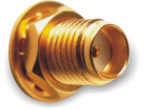
There is a SMA-jack antenna connector on panel of radio modem. On your antenna cable use only respective type of connector of respective impedance: SMA-plug, 50 Ω. It is recommended to use antenna coaxial cables like this: RG58 up to 10 m, RG213 up to 25 m, H1000 for longer.
Radio modem may be destroyed when antenna or dummy load antenna is not connected!
Ethernet connector RJ-45 for 10BaseT and 100BaseT meets fully standard of Power over Etrhernet IEEE802.3af.
Radio modem recognizes standard or cross cable and adapts itself automatically.
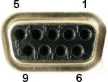
AUX – via RS232 DSUB9 connector, using pins 5 and 9 (see Tab.1). Voltage 10,5–30 V, nominal 13,8 V.
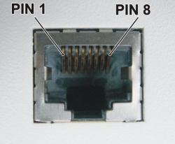
PoE – via Ethernet connector RJ-45 using PoE standard IEEE802.3af. Voltage 38–57 V. Common version of supplying:
plus to pins 4+5
minus to pins 7+8
the polarity can be inverted also
Other options with PoE adapter see the standard IEEE802.3af.! Only ONE from above power possibilities can be used !
LED meanings
| PWR |
|
| TX |
|
| RX |
|
| ETH |
|
| 232 |
|
| STATUS |
|
Tab. 2: Technical parameters
| Frequency range | RE400: 373.25–484 MHz | ||
| Channel bandwith | 25 kHz or 12.5 kHz or 6.25 kHz * | ||
| Frequency step | 5 kHz or 6.25 kHz | ||
| Method of setting working frequency | software | ||
| Rx/Tx switching time | < 1.5 ms | ||
| Data security on RF channel | 32 bit CRC | ||
| Receiver sensitivity for BER 10-3 | better than -107 dBm | ||
| Output power software adjustable | Low | 0.5 W | |
| High | 2 W | ||
| Data rate in RF channel | 2.6 kbps in 6.25 kHz channel * | ||
| 5.2 kbps in 12.5 kHz channel | |||
| 10.4 kbps in 25 kHz channel | |||
| Interfaces | Ethernet, RS232 | ||
| Antenna connector | SMA | ||
| MTBF (Mean Time Between Failures) | >100 000 hodin | ||
| Power method | AUX | PoE | |
| Power supply | 10.8–30 V (nomin. 13.8 V) | 38–57 V | |
| Power consumption (cca) | Idle state (Rx) | 430 mA/13.8 V | 145 mA/48 V |
| Low power Tx | 700 mA/13.8 V | 230 mA/48 V | |
| High power Tx | 950 mA/13.8 V | 310 mA/48 V | |
| Operating temperature range | -25 až +55 °C | ||
| Storage temperature range | -35 až +85 °C | ||
| Case dimensions | 137 × 96 × 31 mm | ||
| Weight | 0.3 kg | ||
* Channel spacing 6.25 kHz is not approved under EU rules.