In Bridge mode, a packet is transmitted to the radio channel immediately, without any checking whether the radio channel is occupied or not. If other radio was transmitting simultaneously, a collision would occur and both packets would be lost. Consequently Bridge mode can be used only for applications which never generate more than a single message at a time, e.g. master-slave polling applications. Still appropriate measures have to be taken to avoid collisions in special situations.
Repeaters can be used in the Bridge mode in order to extend the radio coverage. Considering the repeated packets, it is necessary to schedule the access to the radio channel to avoid systematic collisions. In a polling-type network, there is a request packet from centre to remote, to which the remote responds immediately. When a remote receives the request directly from the centre, its immediate response would collide with the repeated request, so it would be never received by the centre – a perfect example of a systematic collision.
Packet header contains information about the number of Repeaters on the route, i.e. how many times the packet can be possibly repeated. This number is decremented when passing through each Repeater. The remote radio modem which receives the packet must delay its own transmission for a period. This delay is calculated from the number of the remaining repetitions, the packet length and the modulation rate in the radio channel. Repeaters always transmit immediately, without any delay.
Example:
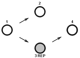
There are 4 radios in the network operated in the Bridge mode. Everyone can receive each other except Radio 4, which is not able to receive Radio 1 and vice versa. Therefore, in the Radio 3 the Repeater function is turned on, and it mediates the connection between 1 and 4.

First, packet A is broadcast from Radio 1.
Radio 2 receives Packet A and sends it to its COM. In the instant when it starts the reception of Packet A, Radio 2 calculates (from information in the received packet header and from number of repeaters in its own setting) the time delay which is needed for the delivery of Packet A through the repeater (repeaters). When the response from the connected device arrives via COM (Packet B), the Radio 2 postpones its transmission for the delay.

In the meantime, Radio 3 (Repeater) receives Packet A and repeats it to the radio channel immediately. Radio 4 receives the Packet A and then Packet B and sends them both to the COM. Packet B is also received by Radio 3 and immediately repeated. Whenever a radio receives a copy± of the same packet during the calculated delay, it discards it as a repeated packet. Note that the picture does not show all the packets at all the radios.
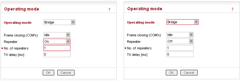
Repeater is configured in the Settings / Device / Operating Mode menu, for Radio 3 (left) and Radio 1, 2, 4 (right):

The delay period based on number of repeaters solves the collision between a repeated packet and a possible response. When more than one repeater is used in a Bridge-mode network, collisions between repeated packets from different repeaters may occur. These cannot be solved by simple delays, rather a sophisticated anti-collision protocol is required. The RipEX Router mode is recommended to be used in more complex networks with multiple repeaters. Nevertheless if certain conditions on signal coverage (sometimes non-coverage) among repeaters, centre and remotes are met, the Bridge mode for a polling-type application can be used. See the chapter Bridge mode in RipEX Manual.
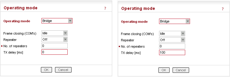
There is also the Tx delay setting in the menu. It shall be used in Bridge mode if multiple RTUs connected to slave stations reply to a broadcast query from the centre. It is necessary to spread out their replies to the radio channel in terms of time, otherwise a massive collision occurs. It can be achieved by setting the TX delay parameter to an adequate sequence of TX delays (e.g. 0, 100, 200 ms as in the example below) in individual remote RipEXes. The slave RipEXes will enter the radio channel successively and no collisions will occur.
Note: The TX delay applies to every packet that is sent out to the radio channel.
Example:
The Centre broadcasts request and the RTUs 1, 2 and 3 generate the response and send it out to their respective RipEX.

Radios 1, 2 and 3 have the TX delay parameter set to 0, 100 and 200 ms, respectively. Therefore, Radio 1 starts transmitting just after reception of the frame from COM port. Upon 100 ms later, when Radio 1 has completed transmission, Radio2 starts transmitting. Finally, 200 ms after the reception of the packet from RTU, Radio 3 starts its transmission. All three responses are thus sequentially sent to the Centre and no collision happens.

The TX delay parameter coresponds to multiples of maximum packet length expected and shall be set in miliseconds. The packet transmission time through radio channel can be calculated as follows:
t = (n + 12). 8/(b . fec)
where:
t [ms] | – time needed for the packet transmission |
n [ - ] | – number of bytes transmitted (consider the longest possible reply from RTU) |
b [kbps] | – Modulation rate |
fec [ - ] | – Forward Error Correction |
fec = 1.00 if FEC = Off | |
fec = 0.75 if FEC = On |
This calculation gives approximate results ( ± 3ms). When more accurate calculation is necessary, please check the calculation tool on Racom web pages https://www.racom.eu/eng/products/radio-modem-ripex.html#calculation
TX delay is configured in the Settings / Device / Operating Mode menu, for Radio 1 (left) and Radio 2 (right):
