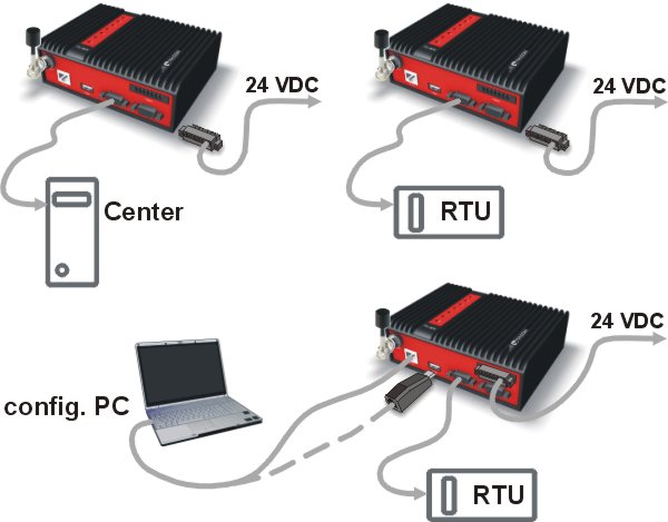
Before installing a RipEX network in the field, a bench-test should be performed in the lab. The RipEX Demo case is great for this as it contains everything necessary: 3 RipEX’s, Power supply, dummy load antennas, etc.
If you use your own installation for lab tests, don’t forget:
A dummy load or an actual antenna with 50 ohm impedance should be connected to the RipEX
The minimum RF output must be set to avoid overloading the dummy antenna and to keep the received signal at reasonable level, between -40 and -80 dBm.
The power supplies must meet the requirements given in the specifications, Section 5.4, “Technical specification”. Make sure the power supplies do not generate interference in the radio channel and that they can handle very fast changes in the load when RipEX switches from reception to transmission and back.
Switch on your power supply. LED PWR flashes quickly and after 8 seconds it switches to a green light. After approximately 30 seconds your RipEX will have booted and will be ready; the STATUS LED shines. You’ll find the description of the individual LED states in Section 5.3, “Indication LEDs”.
To configure a RipEX you can connect it to your PC in three ways:
Using the external Wifi adapter
Using the external ETH/USB adapter
Directly over the Ethernet interface
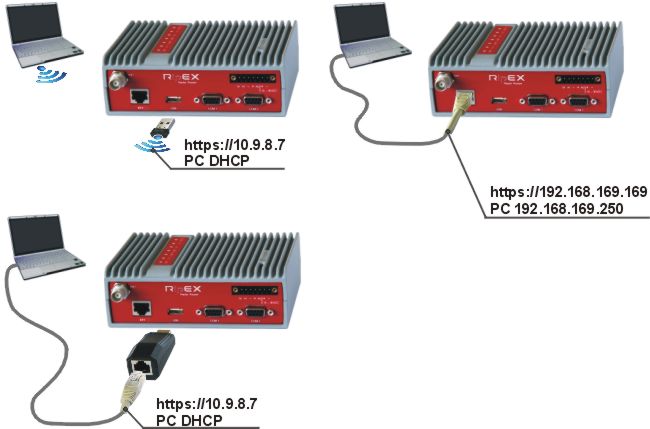
PC connected via Wifi adapter
We recommend using the “W1” – external Wifi adapter (an optional accessory of the RipEX). Connect your PC or tablet or smart phone to RipEX Wifi AP first. Its default SSID is “RipEX + Unit name + S/N”. The W1 contains a built-in DHCP server, so if you have a DHCP client in your PC (as most users do), you don’t need to set anything up. The RipEX’s IP address for access over the ETH/USB adapter is fixed: 10.9.8.7.
Go to Login to RipEX.
PC connected via ETH/USB adapter
We recommend using the “X5” – external ETH/USB adapter (an optional accessory of the RipEX). The ETH/USB contains a built-in DHCP server, so if you have a DHCP client in your PC as most users, you don’t need to set anything up. The RipEX’s IP address for access over the ETH/USB adapter is fixed: 10.9.8.7.
Go to Login to RipEX.
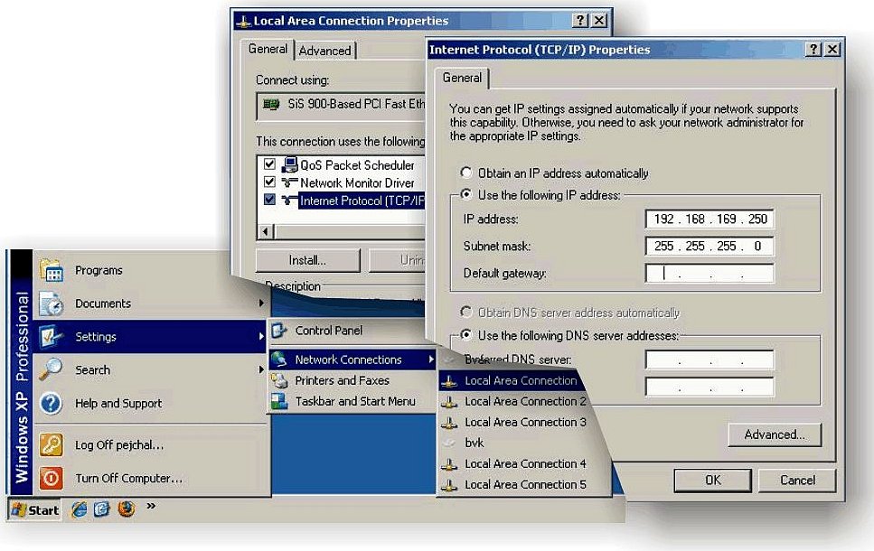
PC connected directly to ETH port
Set a static IP address in PC, example for Windows XP:
Start > Settings > Network Connections > Local Area Connections
Right Click > Properties > General
select Internet Protocol (TCP/IP) > Properties > General
IP address 192.168.169.250 – for RipEX in the default state
Subnet mask 255.255.255.0
Default gateway leave empty
OK (Internet Protocol Properties window)
OK (Local Area Properties window)
Some Operating systems may require you to reboot your PC.![[Important]](/images/radost/images/icons/important.png)
Important When you change the RipEX ETH address from the default value later on and the new IP network does not include the default one, you will have to change your PC’s static IP again to be able to continue configuring the RipEX.
Start a web browser (Mozilla Firefox, Internet Explorer – JavaScript enabled) on your PC and type the RipEX’s default IP in the address line default IP address in the address line field:
10.9.8.7 – when connected via external ETH/USB or Wifi adapter. IP address 10.9.8.7 is fixed and cannot be changed; it is independent of the IP address of the RipEX’s Ethernet interface.)
192.168.169.169 – when connected directly to ETH
![[Note]](/images/radost/images/icons/note.png)
Note https – For security reasons the http protocol with ssl encryption can be used for the communication between the PC and RipEX. The https protocol requires a security certificate. You must install this certificate into your web browser (Mozilla Firefox, Internet Explorer). The first time you connect to the RipEX, your computer will ask you for authorisation to import the certificate into your computer. The certificate is signed by the certification authority s.r.o. It meets all security regulations and you need not be concerned about importing it into your computer. Confirm the import with all warnings and exceptions that your browser may display during installation.
The login screen appears:
The default entries for a new RipEX are:
User name: admin
Password: admin
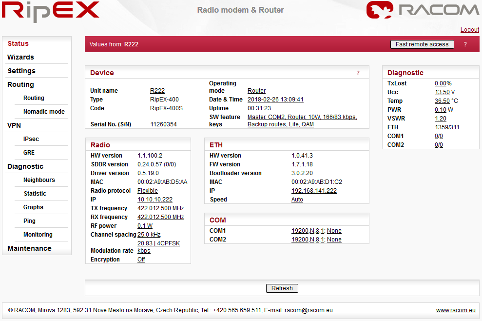
Click OK.Initial screen should appear then:
Warning: Before you start any configuration, make sure only one unit is powered ON. Otherwise, a different radio modem could reply to your requests! (All units share the same IP address and are in Bridge mode when in factory settings.)
IP address unknown
If you don’t have the adapter or you have forgotten the password, you can reset the access parameters to defaults, see Section 5.2.7, “Reset button”.
For the first functionality test we recommend that you use the setup wizard. The wizard will guide you through basic functionality setup. Simply select Wizard in the web interface and proceed according to the information on the screen. Repeat for all RipEX’s in the test network.
If you want to test applications which require a more complex setup, see Chapter 7, Advanced Configuration. To setup the IP addresses you can use the examples in Section 2.3.3, “Router – Flexible, Configuration examples” as your models, or the RipEX-App. notes, Address planing.
To test radio communication between the RipEX’s you can use the Ping test, under Diagnostic/Ping menu. Setting up and the output of this test are described in chapter Adv. Conf., Tools.
If the radio communication between RipEX’s is functional, you can proceed with a test of communication between the connected devices.
You can monitor the status of configuration using the diodes on the LED panel, see Section 5.3, “Indication LEDs”.