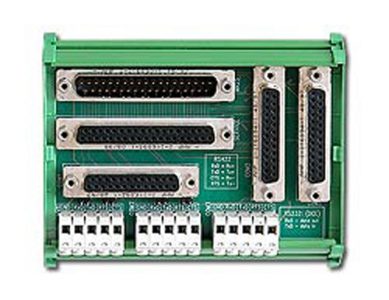
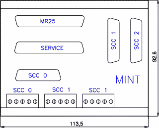
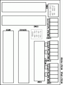
MINT is used for connecting COM ports from the MR25 radio modem inside switchboards. As standard the MINT board is connected to the MR25 using cable DKR10(DSUB37M <–> DSUB37F)
MINT
https//www.racom.eu/eng/products/mint.html
Description
The following collectors are mounted as standard on the printed circuit board:
- DSUB37M – complete MR25 interface, output from the radio modem
- DSUB37F – the connector serves for connecting the service device; DSUB37 connectors are connected in parallel
- CUM/CUF (detachable screw connectors) – the connectors are mounted in a group of five for individual ports (the following signals are fed out: RxD, TxD, RTS, CTS, GND); CUM/CUF connectors are fully mounted, i.e. the part to the printed circuit CUM and the slip-on part with screw terminal CUF
Two types of MINT interface are manufactured:
- MINT – serial ports are fed out to CUM/CUF connectors
- MINT/S – the printed circuit is additionally mounted with a DSUB25F connector for each individual serial port (see image); signals are fed to these connectors in accordance with the standard V.24 (RS232)
On the printed circuit it is possible to make the connection required for the RS485 interface using short-circuit jumpers on CUM/CUF connectors. It is possible to create a loopback outside the MR25 radio mode using the jumper between RxD and TxD (e.g. for testing converters of individual COM ports). Only signals corresponding to the MR25 hardware version are functional on the MINT PCB – see the publication Versions of the MR25 radio modem.
Description of individual pins on DSUB25F according to the standard V.24:
| pin | signal | pin | signal | pin | signal | pin | signal |
|---|---|---|---|---|---|---|---|
| 2 | TxD/Tx+ | 6 | DSR | 17 | RxC | 25 | TI |
| 3 | RxD/Rx+ | 7 | GND | 18 | LAL | ||
| 4 | RTS/Tx- | 8 | CD | 20 | DTR | ||
| 5 | CTS/Rx- | 15 | TxC | 21 | RDL |


