https//www.racom.eu/eng/products/m/mg100/index.html
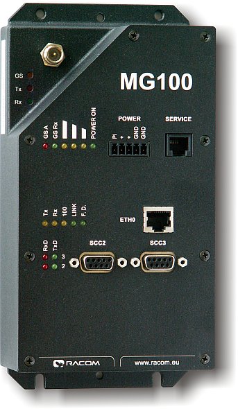
Table of Contents
List of Figures
- 1. Router MG100 with Cannon connectors
- 3.1. Connector type FME
- 3.2. RS232 DSUB9 female
- 3.3. Data cable RS485 connections
- 3.4. Labelling of serial interface terminals
- 3.5. RJ-45F
- 3.6. Wiring diagrams for analog and digital inputs and outputs
- 3.7. Description of analog and digital inputs and outputs
- 3.8. Examples of wiring analog inputs and outputs
- 3.9. Power connector & information LED
- 3.10. Information LEDs
- 3.11. Service connector
- 3.12. Service cable connector connections
- 3.13. View of GPRS router — description of connectors, model with DSUB (Canon) connectors and with terminals
- 5.1. Mounting dimensions
- 6.1. Example of a typical installation of a data network radio point
- 6.2. Example of the layout of equipment in a switchboard
- 7.1. Declaration of conformity MG100i
- 7.2. Consistency declaration MG100
- 7.3. Country of Origin declaration
List of Tables
- 3.1. Table of data connector RS232 connections
- 3.2. Table of data connector RS422 connections
- 3.3. Table for distinguishing LEDs for RxD and TxD by colour
- 3.4. Table of Ethernet to cable connector connections
- 3.5. Table of digital and analog input and output parameters
- 3.6. Modes of LED diodes Power
- 3.7. Modes of LED diode GS for MG100M, MG100M2and MG100M3
- 3.8. Modes of LED diodes GS for MG100M4
- 3.9. Modes of LED diodes GS for MG100M0
- 3.10. Table of service connector connections
- 3.11. Slot options
- 4.1. Table of technical parameters
- 4.2. Standards complied