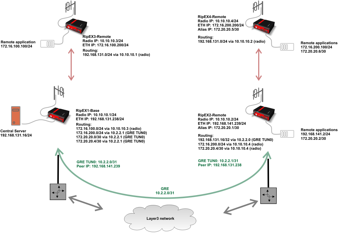
In this example, 4 RipEX units will be interconnected using a GRE tunnel. Routing will be configured for particular subnets and the communication will be verified.
RipEX1, acts as a centre for three remote units. Flexible Router mode will be utilized. Each RipEX is connected via Ethernet to its own local network and two remote RipEX units simulate using several subnets by “Alias” addresses (e.g. SLIP protocol). The Radio network subnet is 10.10.10.0/24. The GRE tunnel is not used on the radio channel. It is only utilized on the Ethernet network.
This example shows how a GRE tunnel can be used to route data via any L3 network without being able to alter the routing rules of this network – i.e. we cannot add RipEX subnets to the current routers, firewalls or other existing infrastructure. That’s the reason to encapsulate all data to GRE, changing all packets to have IP headers from routable subnets – i.e. 192.168.131.0/24 and 192.168.141.0/24 in our example.
The RipEX configuration can be performed via Ethernet, USB/ETH or USB/WiFi access. Another option is to use the “Fast Remote Access” feature from any of the units to configure the rest of the network.
There is only one GRE tunnel. Both end-points are RipEX units; there is no need for any other external device.
RipEX1-Base <--> RipEX2-Remote:
10.2.2.0/31