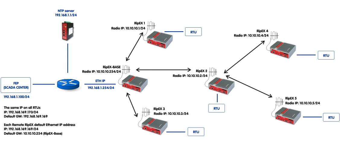
The example shows an ideal situation where all RTU’s in network have the same IP address, but still operate with no issue. All remote RipEX units (all units except one Base station) share almost the same configuration with default Ethernet IP address. The only differences are the Radio IP addresses which are also used in NAT configuration.
NAT enables a defined communication to be transformed (changing IP addresses or ports) upon configured filter rules. In this example, we use this feature to:
Enable Modbus TCP application to run over TCP port 502
Destination NAT
Enable NTP time synchronization using the Radio IP addresses only (Ethernet IPs not required)
Source NAT
NOTE:
If you need full access via all possible ways,
regular routing without NAT must be configured. NAT enables running of
specific applications “only”.
Destination NAT example details:
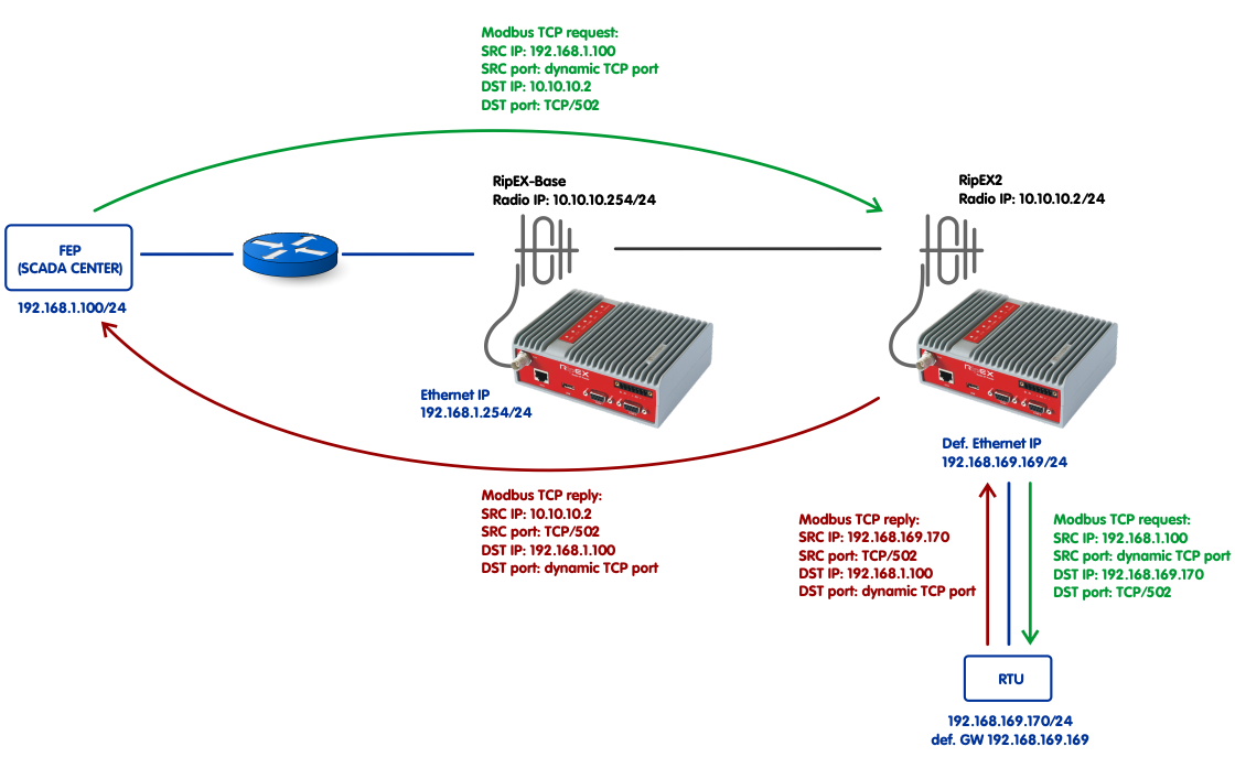
Destination NAT handles packets received on the Radio interface of remote RipEX units. Once the packet is received and a filter matches the destination TCP port to be 502 and the destination IP to be the radio IP of that particular RipEX (10.10.10.2), NAT changes the destination IP address to be the RTU’s IP address (192.168.169.170).
The RTU replies and RipEX2 makes an opposite transition and changes the source IP address back to 10.10.10.2. This rule does not need to be defined manually but is working upon a dynamic rule created internally because of the Destination NAT rule. This is general functionality of any NAT implementation.
NOTE:
If the traffic would be initiated from the RTU
instead of initiating the TCP session from SCADA Center, the Source NAT
must have been configured so the SRC IP of this packet is changed to
10.10.10.2 instead of 192.168.169.170.
Source NAT example details:
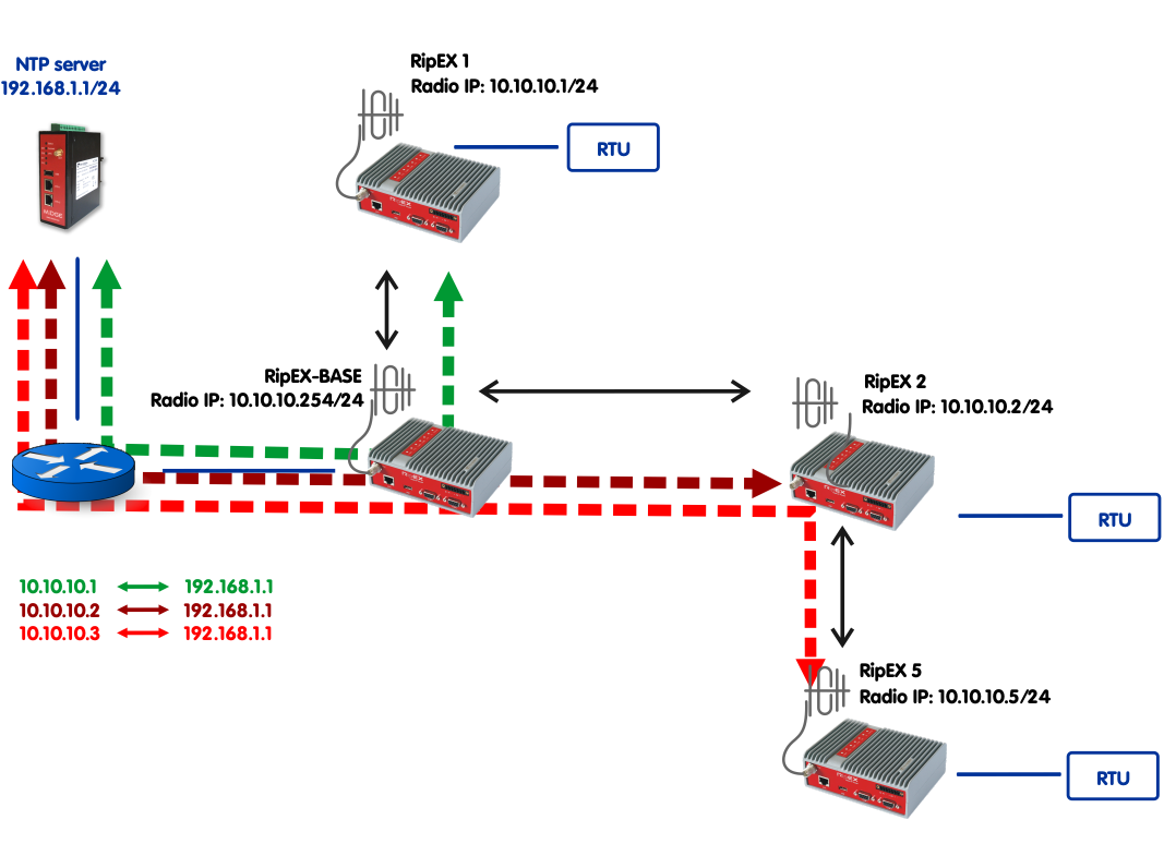
Source NAT in this example is used for NTP time synchronization of RipEX units. RipEX can be synchronized via NTP and for its NTP requests, it automatically uses Ethernet IP addresses. If, for any reason, remote RipEX units share the same Ethernet IP address (used in this example), or the network is ready for only routing the Radio IP addresses, NAT can be used to change the source IP address (192.168.169.169) to be the Radio IP address (10.10.10.x). Without NAT, the NTP server would reply to 192.168.169.169 IP which is used in many remote RipEX units and there is no routing configured for 192.168.169.0/24 network in the NTP server.
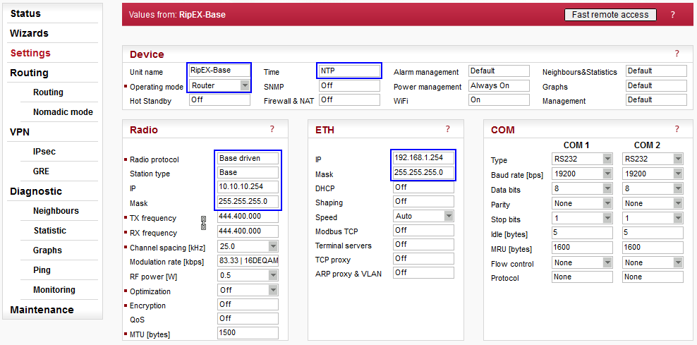
Parameters:
| Unit name | RipEX-Base |
| Operating mode | Router |
| Time | NTP |
| Radio protocol | Base driven |
| Station type | Base |
| Radio IP/Mask | 10.10.10.254/255.255.255.0 |
| ETH IP/Mask | 192.168.1.254/255.255.255.0 |
The network is configured using Base driven Radio protocol due to its easier configuration and TCP optimization. Set the Unit name, select the Router mode and configure correct IP addresses.
Open the Radio protocol menu and configure the protocol details.
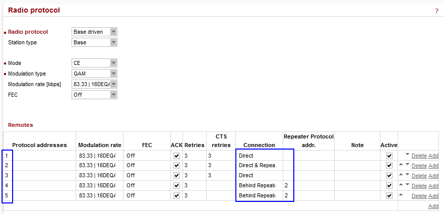
Configure any Mode, Modulation type and rate, but keep the Mode and type the same within the whole network.
NOTE:
The Modulation rates and other parameters can
be different for remote units. Please see more details in the
Autospeed
application note.
Configure all 5 remote RipEX units and focus on the “Connection” and “Repeater Protocol addr.” columns.
Protocol address 1 – Direct connection
Protocol address 2 – Direct connection and configured as Repeater
Protocol address 3 – Direct connection
Protocol address 4 – Behind the Repeater #2
Protocol address 5 – Behind the Repeater #2
There is no need for any Routing rules. As stated earlier everything is controlled by the Base station by this Remotes’ table and BDP functionality. The Routing menu is empty.
NOTE:
Please see more details in the
BDP
application note.
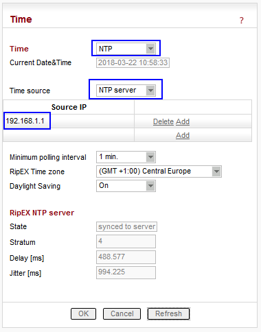
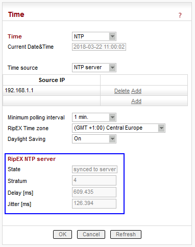
This central RipEX unit is synchronized via NTP protocol. The NTP server’s IP is 192.168.1.1, cellular router M!DGE is used within this example.
NOTE:
Please see more NTP configuration details in
M!DGE
Manual.
Check the RipEX NTP server state after applying the changes to see if it is already synced or not.
RipEX-Base is NOT configured with NAT functionality. NAT is set in all remote units for Modbus TCP port 502 and NTP (UDP port 123). RipEX-Base does not require NAT for NTP synchronization, it uses 192.168.1.254 Source IP address for its request and the NTP server successfully replies to these requests (no routing required, L2 layer accessibility).
Apply all the changes and configure remote units.
All remote RipEX units have the same configuration except:
Unit name
Radio IP address
NAT rules (particular Radio IP is used)
Common parameters for all remote units (blue):
| Operating mode | Router |
| Time | NTP |
| Radio protocol | Base driven |
| Station type | Remote |
| Radio Mask | 255.255.255.0 (default) |
| ETH IP/Mask | 192.168.169.169 / 255.255.255.0 (default) |
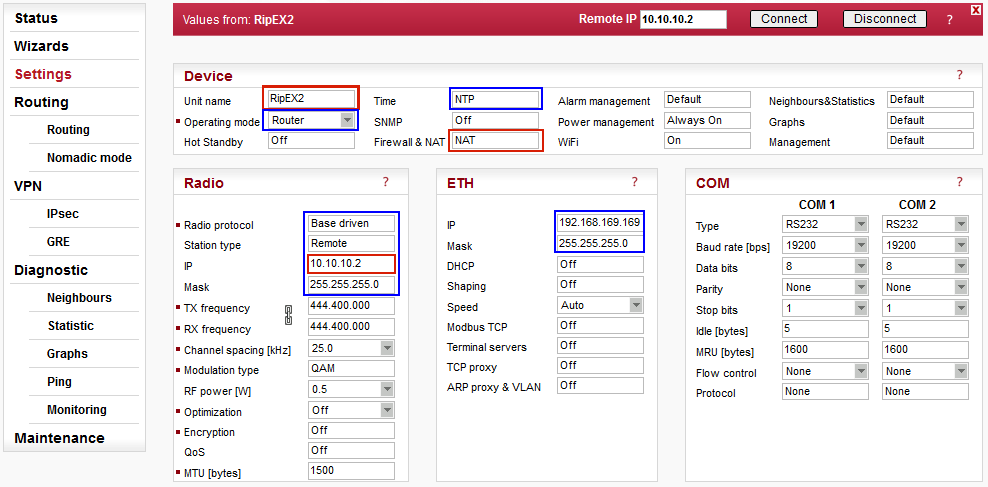
Unique parameters for particular RipEX unit (red):
| Unit name | RipEX2 |
| Firewall & NAT | NAT |
| Radio IP | 10.10.10.2 |
The network is configured using Base driven Radio protocol. Set the Unit name, select the Router mode and configure correct IP addresses.
Open the Radio protocol menu and configure the protocol details.
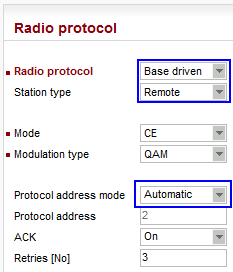
All remote units share completely the same BDP configuration.
Parameters:
| Radio protocol | Base driven |
| Station type | Remote |
| Protocol address mode: | Automatic |
The Protocol address is automatically set based on the last Radio IP digit.
The NTP is configured in the same way as the Base unit. See the NAT configuration for differences.
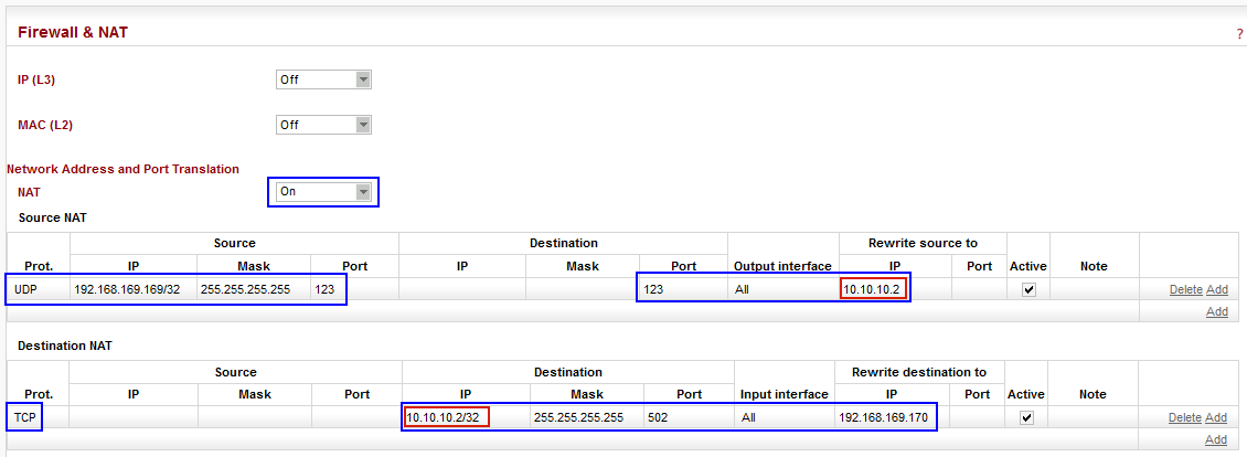
Turn on the NAT functionality and define one Source NAT and one Destination NAT rule.
Common Source NAT configuration for all remote units (blue):
| Protocol | UDP |
| Source IP | 192.168.169.169/32 (default Ethernet IP) |
| Source Mask | 255.255.255.255 |
| Source Port | 123 |
| Destination Port | 123 |
| Output interface | All |
Unique Source NAT configuration for particular remote RipEX (red):
| Rewrite source to (IP) | 10.10.10.2 (Radio IP) |
The Source NAT changes the Source IP address for RipEX NTP requests – instead of Ethernet IP (192.168.169.169), use the actual Radio IP (10.10.10.2).
Common Destination NAT configuration for all remote units (blue):
| Protocol | TCP |
| Destination Mask | 255.255.255.255 |
| Destination Port | 502 |
| Input interface | All |
| Rewrite destination to (IP) | 192.168.169.170 (connected RTU) |
Unique Destination NAT configuration for particular remote RipEX (red):
| Destination IP | 10.10.10.2/32 |
The Destination NAT changes the Destination IP to 192.168.169.170, i.e. the RTU IP address (all RTU’s within the network have the same IP address!). The change is done for Modbus TCP application (TCP port 502).
Apply the changes in the Settings menu and configure other units as well.
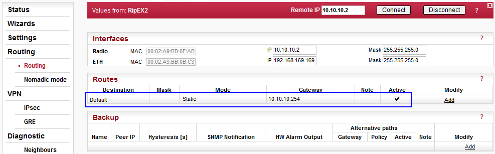
Each remote RipEX requires one routing rule. Either enable the Default route to Base Radio IP 10.10.10.254 or define a static rule for Destination 192.168.1.0/24 via 10.10.10.254 gateway.
The configuration is now complete. Test the functionality.
Source NAT (NTP) Verification
Check if RipEX is synchronized or not in the Settings – Device – Time menu.
No matter if it is synchronized or not, go to the Base RipEX’s Diagnostic – Monitoring menu and run the Monitoring of Radio and Ethernet interfaces as depicted in Figure 2.13. The Monitoring is started by pressing the “Start” button.
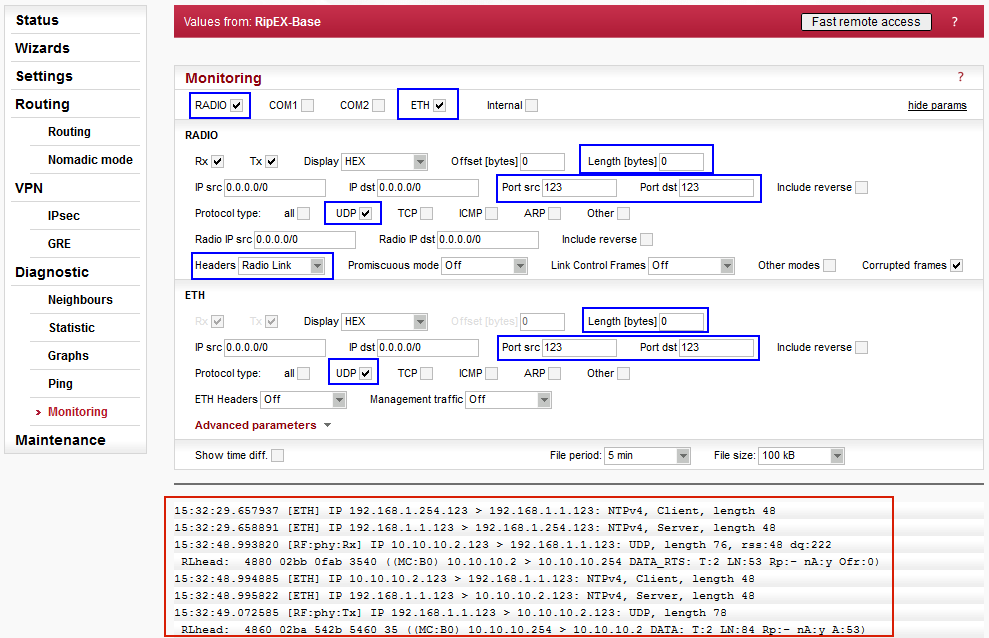
The output example:
15:32:29.657937 [ETH] IP 192.168.1.254.123 > 192.168.1.1.123: NTPv4, Client, length 48
15:32:29.658891 [ETH] IP 192.168.1.1.123 > 192.168.1.254.123: NTPv4, Server, length 48
NTP synchronization of RipEX-Base, NAT is not used of course
15:32:48.993820 [RF:phy:Rx] IP 10.10.10.2.123 > 192.168.1.1.123: UDP, length 76, rss:48 dq:222
RLhead:  4880 02bb 0fab 3540 ((MC:B0) 10.10.10.2 > 10.10.10.254 DATA_RTS: T:2 LN:53 Rp:- nA:y Ofr:0)
15:32:48.994885 [ETH] IP 10.10.10.2.123 > 192.168.1.1.123: NTPv4, Client, length 48
15:32:48.995822 [ETH] IP 192.168.1.1.123 > 10.10.10.2.123: NTPv4, Server, length 48
15:32:49.072585 [RF:phy:Tx] IP 192.168.1.1.123 > 10.10.10.2.123: UDP, length 78
RLhead:  4860 02ba 542b 5460 35 ((MC:B0) 10.10.10.254 > 10.10.10.2 DATA: T:2 LN:84 Rp:- nA:y A:53)
NTP request received on the Radio channel from 10.10.10.2 IP address (NAT worked)
Radio Link header displays that the Radio IP destination is the Radio IP of Base (correct)
Data go via Ethernet and then NTP reply is transmitted back to 10.10.10.2
If you see any NTP request from 192.168.169.169 IP address, NAT is not configured correctly in remote units. Or if you see a request from 10.10.10.254, NAT is configured in Base too (disable NAT in Base).
NOTE:
You can check the Radio interface monitoring
in remote RipEX units as well.
Destination NAT (Modbus TCP) Verification
Start the Monitoring again, but change the required filters (TCP port 502).
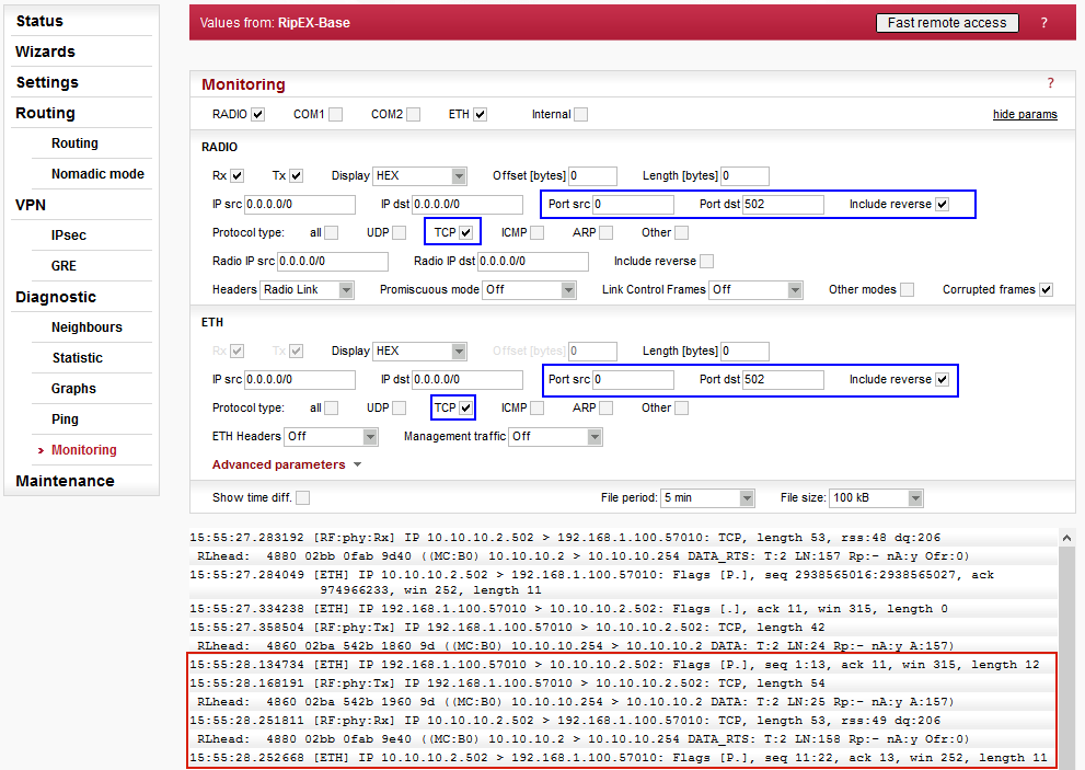
Notice the “Include reverse” check box. This option enables monitoring of data having TCP port 502 used as Source or Destination.
The output example:
15:55:28.134734 [ETH] IP 192.168.1.100.57010 > 10.10.10.2.502: Flags [P.], seq 1:13, ack 11, win 315, length 12
15:55:28.168191 [RF:phy:Tx] IP 192.168.1.100.57010 > 10.10.10.2.502: TCP, length 54
RLhead:  4860 02ba 542b 1960 9d ((MC:B0) 10.10.10.254 > 10.10.10.2 DATA: T:2 LN:25 Rp:- nA:y A:157)
15:55:28.251811 [RF:phy:Rx] IP 10.10.10.2.502 > 192.168.1.100.57010: TCP, length 53, rss:49 dq:206
RLhead:  4880 02bb 0fab 9e40 ((MC:B0) 10.10.10.2 > 10.10.10.254 DATA_RTS: T:2 LN:158 Rp:- nA:y Ofr:0)
15:55:28.252668 [ETH] IP 10.10.10.2.502 > 192.168.1.100.57010: Flags [P.], seq 11:22, ack 13, win 252, length 11
Four packets are inspected. The first one is Modbus TCP request from the SCADA Center to 10.10.10.2 remote RipEX and this packet is sent out via Radio channel. Other two packets are the Modbus TCP reply received on the Radio channel and sent out via Ethernet to SCADA Center.
We can only “believe”, NAT is working correctly. You can check it in your application, but the NAT functionality is more easily visible in the remote RipEX. Run the same Monitoring capture in remote RipEX unit.
The output example:
16:06:58.290274 [RF:phy:Rx] IP 192.168.1.100.57010 > 10.10.10.2.502: TCP, length 54, rss:48 dq:206
RLhead:  4860 02ba 542b a960 79 ((MC:B0) 10.10.10.254 > 10.10.10.2 DATA: T:2 LN:169 Rp:- nA:y A:121)
16:06:58.291212 [ETH] IP 192.168.1.100.57010 > 192.168.169.170.502: Flags [P.], seq 974974513:974974525, ack 2938572617, win 381, length 12
16:06:58.292021 [ETH] IP 192.168.169.170.502 > 192.168.1.100.57010: Flags [P.], seq 1:12, ack 12, win 254, length 11
16:06:58.361105 [RF:phy:Tx] IP 10.10.10.2.502 > 192.168.1.100.57010: TCP, length 53
RLhead:  4880 02bb 0fab 7a41 ((MC:B0) 10.10.10.2 > 10.10.10.254 DATA_RTS: T:2 LN:122 Rp:- nA:y Ofr:1)
In the above monitoring, RipEX received data on the Radio channel with destination IP addres 10.10.10.2 (and TCP port 502). On the Ethernet, the destination IP is 192.168.169.170 because of NAT translation. The port is the same. Modbus TCP reply is captured on two interfaces (ETH, Radio). Notice the NAT rule works for the opposite direction as well.
NOTE:
It is better to access remote RipEX locally
(e.g. via USB/ETH adapter) or save the Monitoring into a file and read
it afterwards in a text editor. Remote monitoring can overload the Radio
channel.
Applying configuration changes in NAT menu causes a reboot of RipEX unit – keep this in mind.