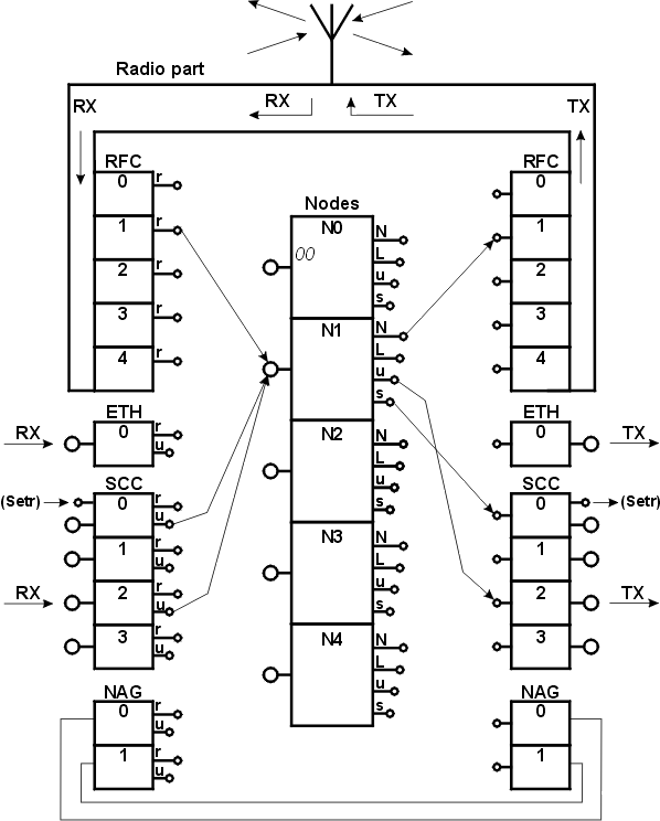
The MORSE communication unit layout is in principle equal for different devices like MR400, MC100, MR900, MR25, MR25ET, sw MORCE or WALRUS. This devices can differ with some blocks presence or it’s number but the configuration procedure stays the same. The diagrams and descriptions presented corresponds with the products family MR400 if it is not written differently.
CU (Communication Unit) can be represented from the point of view of configuration as:
Individual blocks are always fitted with one input (from the left) and one or more outputs (to the right). Packets pass through the diagram from left to right. An exception is the antenna terminal above, which the received signal passes through into the CU and alternately the sent signal passes out through to the antenna.
In the centre there are 5 nodes, which are the basic centre controlling communication. In reality they aren’t boxes with terminal but parts of the program in the processor. From the point of view of configuration it is 5 independent control units, each with 1 input point and 4 outputs. Inside they are equipped with decision-making logic for controlling the flow of packets (routing). Each node can have a different address assigned to it under which it enters the MORSE network (thus one CU can be part of several independent networks).
The Radio part is marked in the upper part of the picture. It is common for the whole CU and individual nodes use it alternately. Its outputs pass through the radio-frequency channel (RFC), which according to the set rules enable routing of packets from nodes to transmitting radio parts. The receiving part of the RF channel transfers packets received from the RF medium to the node to which it is connected by the set configuration.
Serial Communication Channels (SCC) drawn in the lower part receive packets from external devices, modify them to the standard MORSE packet form and route them to the node. In its output part it then enables the output of packets from the node to the user device.
Ethernet Channel (ETH) enables input and output of packets between the Ethernet network and the MORSE network node.
Network agent (NAG) is a virtual channel without the physical output. It receives the packets from the node similarly like other channels, proceeds them and sends them again to the input of some node.
The mentioned blocks are connected via communication lines according to the selection in configuration. Here, for example, at the input of node 1, 3 lines converge from RFC1, SCC0 and SCC2, and from its outputs 3 lines lead out in various directions. As a rule more lines can converge at the input however at the output only one direction of further progression of the packet can be defined. Lines are configured independently for receiving and transmitting. For example the connection from SCC0 to node 1 is different than from node 1 to SCC0
Notes on configuration
Nodes are numbered 0 to 4. Node 0 has an address firmly assigned. It is the serial number, which always starts with 00, for example 0049B897. According to this number (address) it is possible to identify a CU at any time and by means of a so-called path-packets it can be used for establishing a connection. The address can be arbitrary assigned to other nodes and used for normal communication. There are four node outputs:
| N | net | Network output to the radio network medium, Ethernet or net lines |
| L | line | Line output to wire link between two CU´s |
| u | user | User output for user data |
| s | service | Service output for Setr service terminal |
SCC, ETH and NAG channels have a routing output, which is used for transferring packets inside the MORSE network and a user output used for packets which have come from outside to the MORSE network.
RFC channels have only a routing output for transmitting packets through the radio network. The user output would be of no use to the RFC.
Configuration parameters, i.e. the above-mentioned connections between channels and nodes and many other parameters that influence functions of the MORSE network are set using the service terminal. It is a normal PC connected by serial cable or ethernet and running the SETR.exe program, freely supplied by Racom.
