RAy2 utilises SNMP versions SNMPv1 and SNMPv2c – using a community string for authentication, which is by default “mwl-snmp“, but can be changed. SNMP uses UDP protocol for communication; delivery checks are implemented from version 2 onwards.
| Note | |
|---|---|
The RAy2 MIB module complies with Severity level 3 validation. |
By default RAy2 uses UDP port 161 (SNMP) for queries. The manager, which sends the query, dynamically chooses the source port. The use of destination port 161 is fixed. RAy2 replies from port 161 to the port dynamically selected by the manager.
RAy2 launches the SNMP agent automatically on start-up if enabled. RAy2 also sends alarm states (traps) to the manager via the port 162 (SNMPTRAP).
| Note | |
|---|---|
To see the RAy2 MIB table, download it from the RAy2 web interface () and use any document reader you prefer. |
| Note | |
|---|---|
Since RAy2 FW 2.2.5.0, the SNMP non-table items OIDs are defined in accordance with the RFC (ending ‘.0’) – to improve SolarWinds compatibility. Keep this in mind when upgrading RAy2 firmware. Firmware versions < 2.2.5.0 are able to reply to SNMP queries with OIDs ending with .0, but the reply does not contain .0 in its OID. This works fine for example with Zabbix NMS. SolarWinds does not accept such replies. |
The SNMP agent is switched off by default. You can enable or disable it in the menu.
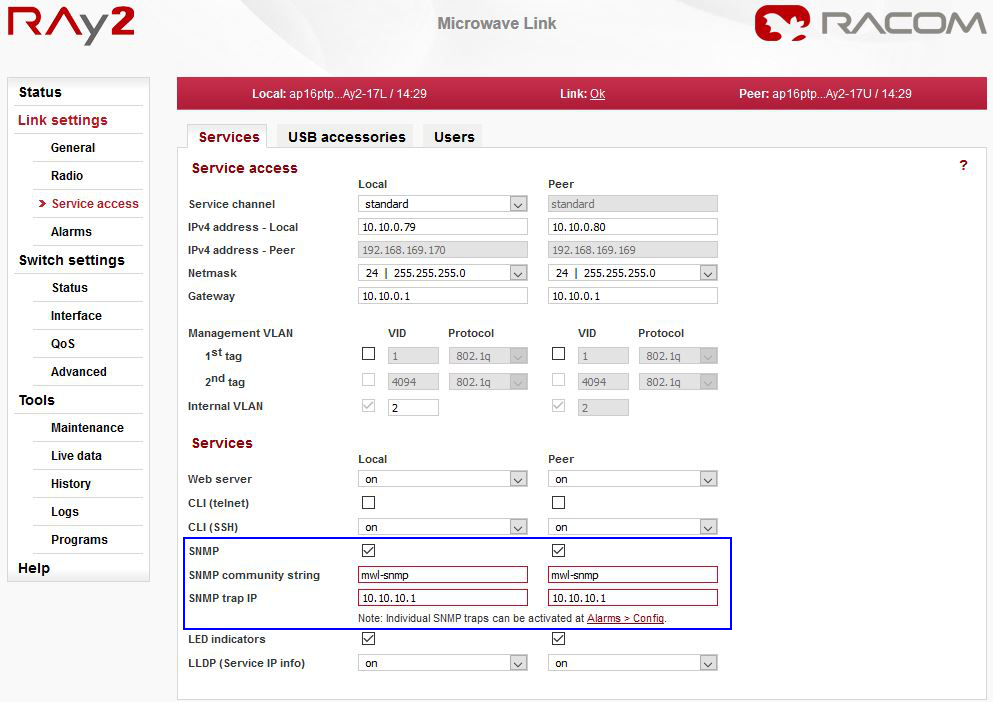
The SNMP community string is “mwl-snmp” by default, but can be changed to another string.
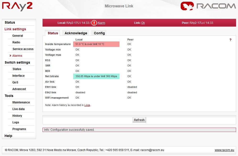
All system alarms are listed on this screen. Inactive alarms are colored white with an “OK” text label. Active alarms are colored according to the severity of the alarm with a text message describing the measured value status.
Alarm severity scale:
critical
major
minor
warning
information
OK (cleared)
acknowledged (confirmed)
| Note | |
|---|---|
If you click on the “Alarm” text (if any Alarm is UP) on the top of the screen (next to the exclamation mark), you will be redirected to this Alarms – Status screen. |
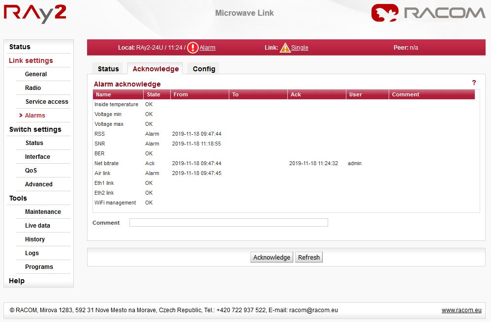
Alarm acknowledgement is a way to let the operator confirm the system is in alarm state. Only an active alarm can be acknowledged.
Multiple selection of active alarms (to acknowledge groups of alarms) can be performed using Shift or Ctrl keys.
The link diagnostic system monitors the operation of the unit. It generates various output of events – system warnings and alarms. The event is always written to the system log and indicated in the status bar and Alarm – Status screen. Some events have adjustable thresholds. Events with no adjustable thresholds may either be Enabled or Disabled. If they are Disabled, the system event is not activated even if the system status is changed. For each event you can choose whether the SNMP trap should be sent if the event occurs.
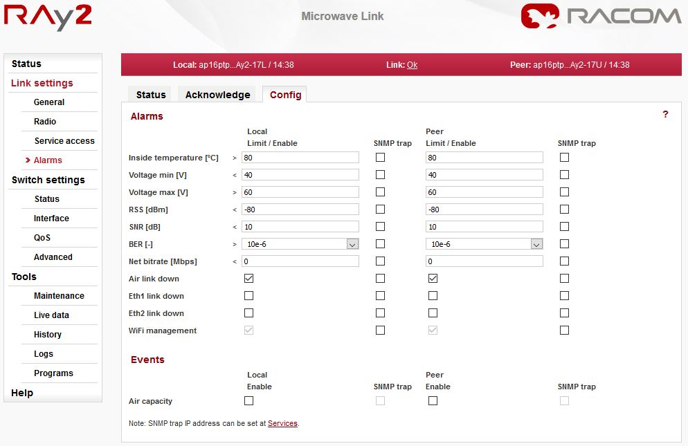
Configurable Alarms / Events:
Inside temperature [°C] | Temperature inside the unit (on the modem board) |
Voltage min [V] | Supply voltage Lower threshold |
Voltage max [V] | Supply voltage Upper threshold |
RSS [dBm] | Received Signal Strength |
SNR [dB] | Signal to Noise Ratio |
BER [-] | Bit Error Rate is registered at the receiving end; instantaneous value |
Net bitrate [Mbps] | The system warning is generated when the radio channel current transfer capacity drops below the set threshold |
Air link down | Radio link interruption |
Eth1/Eth2 link down | Corresponding user Eth link (Eth1/Eth2) on station interrupted |
WiFi management | Warning is generated when WiFi passphrase is not set or WiFi adapter is permanently enabled |
Air capacity | Event is generated when Net bitrate of the air channel changes (e.g. because of ACM operation) |
| Note | |
|---|---|
For all these traps, there are also special OIDs for the alarm states. The states can be one of “n/a”, “up”, “down”, “ack”. See the Application “Alarms” within the RAy2 template. |