The examples of the most common configurations.
Description of communication:
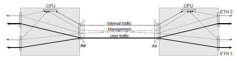
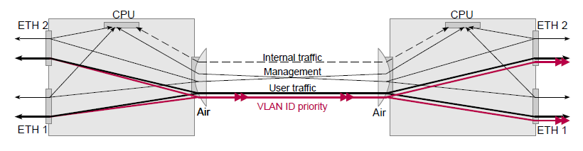
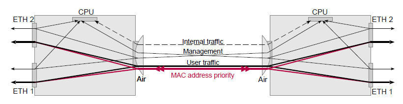
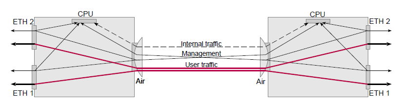
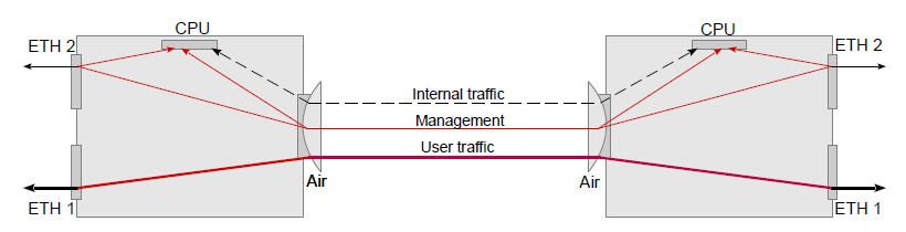
User traffic entering the ETH 1 can be output to a remote station from ETH 1 or ETH 2. Additionally, packets entering ETH 2 can be output to a remote station from ETH 1 or ETH2.
Ports ETH1 to ETH2 are not interconnected. The menu “VLAN / Member / p2, p4”.
The link is transparent for the untagged and tagged frames that are queued according to their priority. The menu “VLAN / VTU priority override / none”.
Management of units is possible from any port. “Management VLAN” is disabled by default and when turned on, the switch does not need to be set.
Internal traffic uses the “Internal VLAN” and has the highest priority set (7). It is queued number 3, again with the highest priority. Valid for “Link settings / Service access / Services / Service channel = standard”. When “Service channel = direct” is set, internal operation with unit IP addresses is performed, without default priority setting.
Setting procedure:
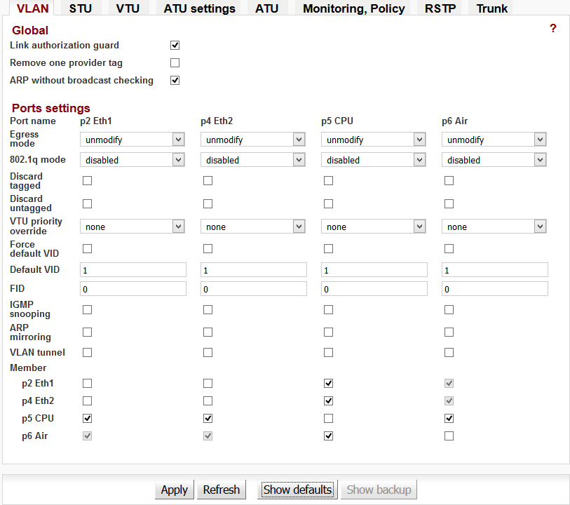
Initial settings: Show defaults
Description of communication:
Connection from port ETH 1 to ETH 2 is added to default
configuration.
Menu “VLAN / Member / p2, p4”.
Setting procedure:
Only set on Local, Remote can be adjusted in the same way if
needed.
Description of communication:
In the internal switch set the priority of a particular VLAN ID. Menu “VTU / Edit / Use VID priority”, “VTU / Edit / VID priority”.
Frames in this VLAN will then pass through the link with a higher priority. After passing through the link the frame retains this new priority. Menu “VLAN / 802.1q / fallback”, “VLAN / VTU priority override / frame”
Setting procedure:
Only set on Local, Remote can be adjusted in the same way if needed.
Local: Step 1, Step 2, Step 3
Step 1
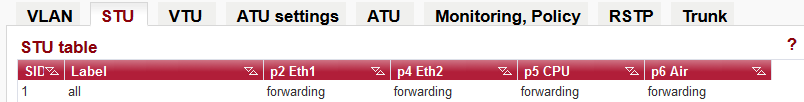
In table STU the item with number SID = 1 is prepared for reference in VTU table.
Step 2
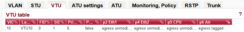
A frame with VID = 10 is assigned priority 6 in VTU table with output mode “egress tagged”.
Step 3
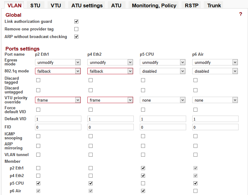
Selecting “802.1q = fallback mode” for the Eth2 and Eth1 port means that the framework prefers to use its own VID when it is contained in VTU (Step 2). The “VTU priority override = frame” causes the frame leaving the RAy unit to have a priority according to VTU table content.
For the “VLAN ID = 10” priority 6 is set. Packets queued with the highest priority (default priority 6 and 7) should never have a higher bit rate than that which is available “in the air” for the lowest modulation ACM. Priorities 6 and 7 also use internal communication packets that are necessary for the link!
For prioritization work, QoS must be enabled under 802.1p (default
setting).
“Switch settings / QoS / 802.1p / Enabled”
Description of communication:
In the switch there is priority set according to the source or destination MAC address. Packets with this MAC address will be queued at a higher priority. The packet passes through the link unchanged.
Setting procedure:
Set the desired MAC address priority to Local, Remote or both dependant on the direction in which we want the packet to travel.
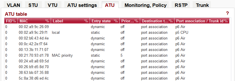
Step 1, Local
“ATU / Edit / Use MAC priority”
“ATU / Edit / Entry
state = static”
“ATU / Edit / MAC priority /
5”

For each link with a “MAC priority” set, Entry state = static, Priority level is selected.
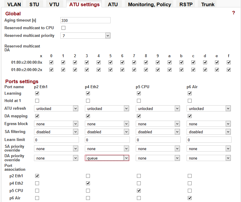
Step 2, Local
“ATU settings / DA priority override / queue”
Step 3, Remote
“ATU / Edit / Use MAC priority”
“ATU / Edit / Entry
state = static”
“ATU / Edit / MAC priority /
5”
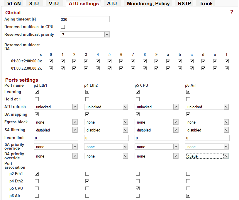
Step 4, Remote
“ATU settings / DA priority override / queue”
For the MAC address 02: 21: 70: 93: d1: 78 the priority 5 is set. Packets in the queue with the highest priority (default priority 6 and 7), should never have a higher data rate than the “air” for the lowest modulation ACM. This priority/queue using packets of internal communications that are required for the link!
Description of communication:
For two separate customers – ETH 1 and ETH 2; management unit is possible from all ports, management VLAN is not set.
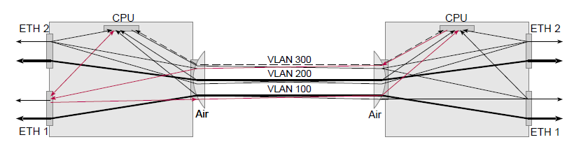
Packets from port ETH 1 are packed into VLAN 100 and transferred to the other side of the link, where they are unpacked and sent in their original format on the ETH 1. Similarly, packets from port ETH 2 are packed into VLAN 200.
Internal communication is also packed in VLAN 300 to set the highest priority.
Setting procedure:
Both units have the same settings.
Remote: Step 1,
Step 2, Step 3, Local: Step 1. Step 2, Step 3
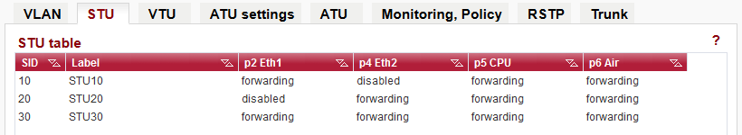
Step 1: STU table
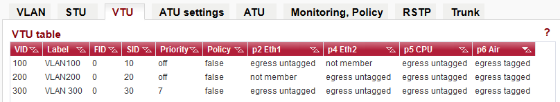
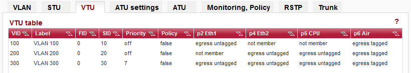
Step 2: VTU table
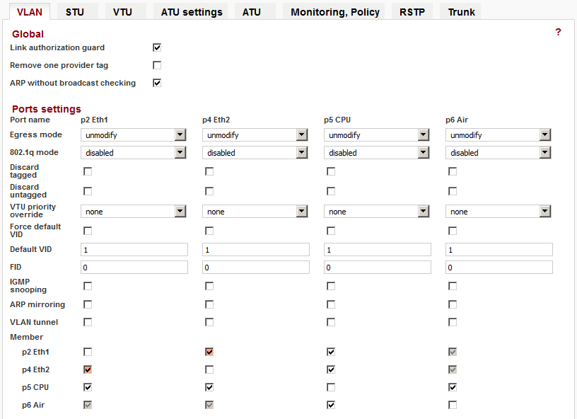
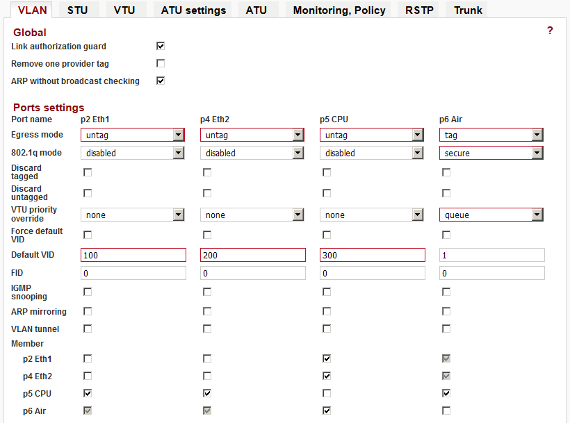
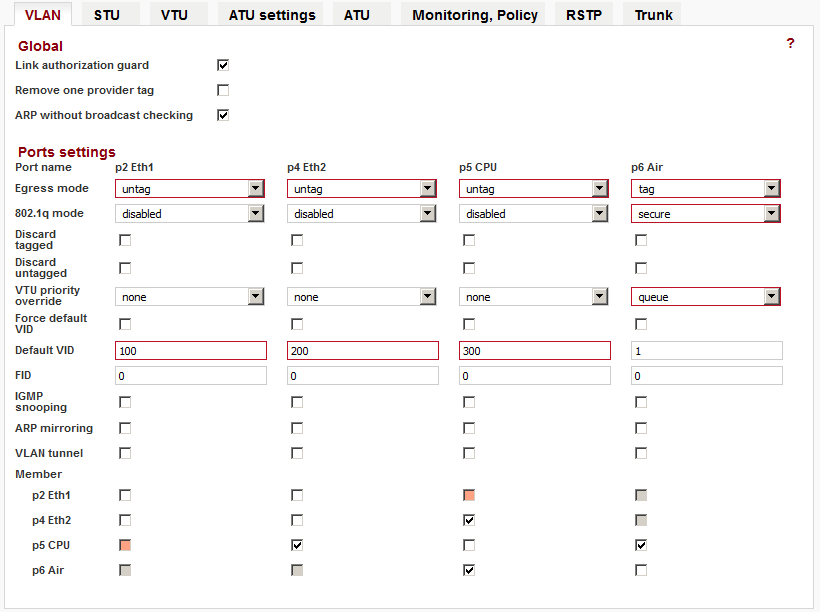
Step 3: VLAN
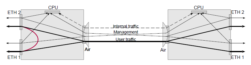
The opening image is simplified to show separation of user traffic. The following figure show the more precise route packets in the VLAN. The diagram highlights the way in which management packets from ETH1 through one VLAN pass towards the CPU. It also highlights packets pass in the other direction from the CPU:
Description of communication:
Unit management is possible from ETH2 port, customer traffic on ETH1, VLAN management not set.
Packets from port ETH 1 are packed into VLAN 100 and transferred to the other side of the link, where they are unpacked and sent in their original format on the ETH 1. These packets can not go to the CPU nor the ETH2 port. Similarly, packets from the EHT 2 port are packaged in the VLAN 200 and can be transferred to the CPU or ETH2 on the opposite side.
Additionally, internal communications are packaged in the VLAN 300 with the highest priority set.
Setting procedure:
Both units have the same settings.
Remote: Step 1,
Step 2, Step 3, Local: Step 1. Step 2, Step 3
Step 1: STU table
Step 2: VTU table
Step 3: VLAN
The opening image is simplified to show the traffic separation. As with the separation of two customers, the packets go in the direction to the CPU via VLAN ID 200 and back are packed into the VLAN ID 300.