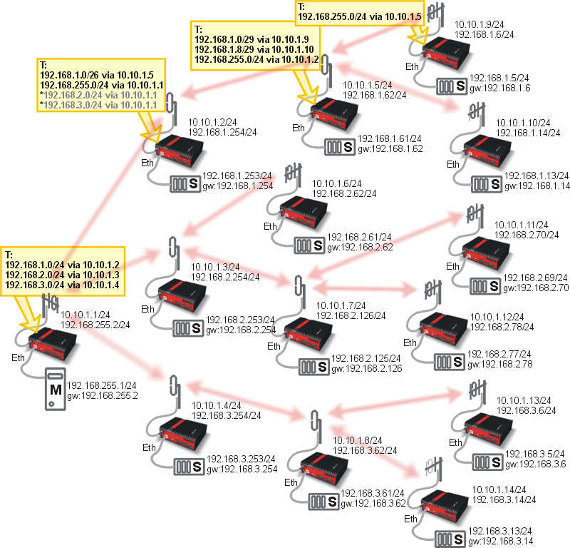
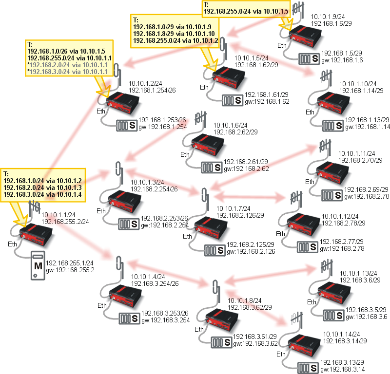
If you can set up IP addresses of the end devices connected over Ethernet, you can simplify routing by hierarchic division into subnets, either complete or for routing purposes only. An example of such network layout follows.
The centre and main repeater form distinct networks with mask 255.255.255.0 (/24), the sub-networks narrow down towards the end devices 255.255.255.192 (/26) and then 255.255.255.248 (/29). Routing tables are only given for a single branch of the network for clarity. They will be similar for other RipEX’s. Only Master – Slave type applications are presumed – without any direct communication between Slave devices.
Virtual network narrowing may also be used, while in reality narrower masks will be only used for routing purposes. This would allow you to use even the addresses reserved for network and broadcasting, though we do not recommend doing so.
Both topology diagrams are too wide for the Base driven protocol. I.e. there are two repeaters on one path to the terminals on the right. This is not supported by the BDP. One solution would be adding an additional RipEX unit to each RipEX two hops from the Base station (e.g. 10.10.1.5) connected via Ethernet (switch), so called “back-to-back”. Then another part of this network will utilize its own BDP with a new Base station (this added RipEX) and original remote units. Note that there cannot be any radio coverage overlap, otherwise the communication will not work (two BDP networks within one radio coverage); in such a case, use different frequencies.
Another difference would be Routing rules, which were explained in previous chapters. Keep in mind that Remote to Remote communication can be very complex and can use too many hops compared to the Flexible mode in this example.

