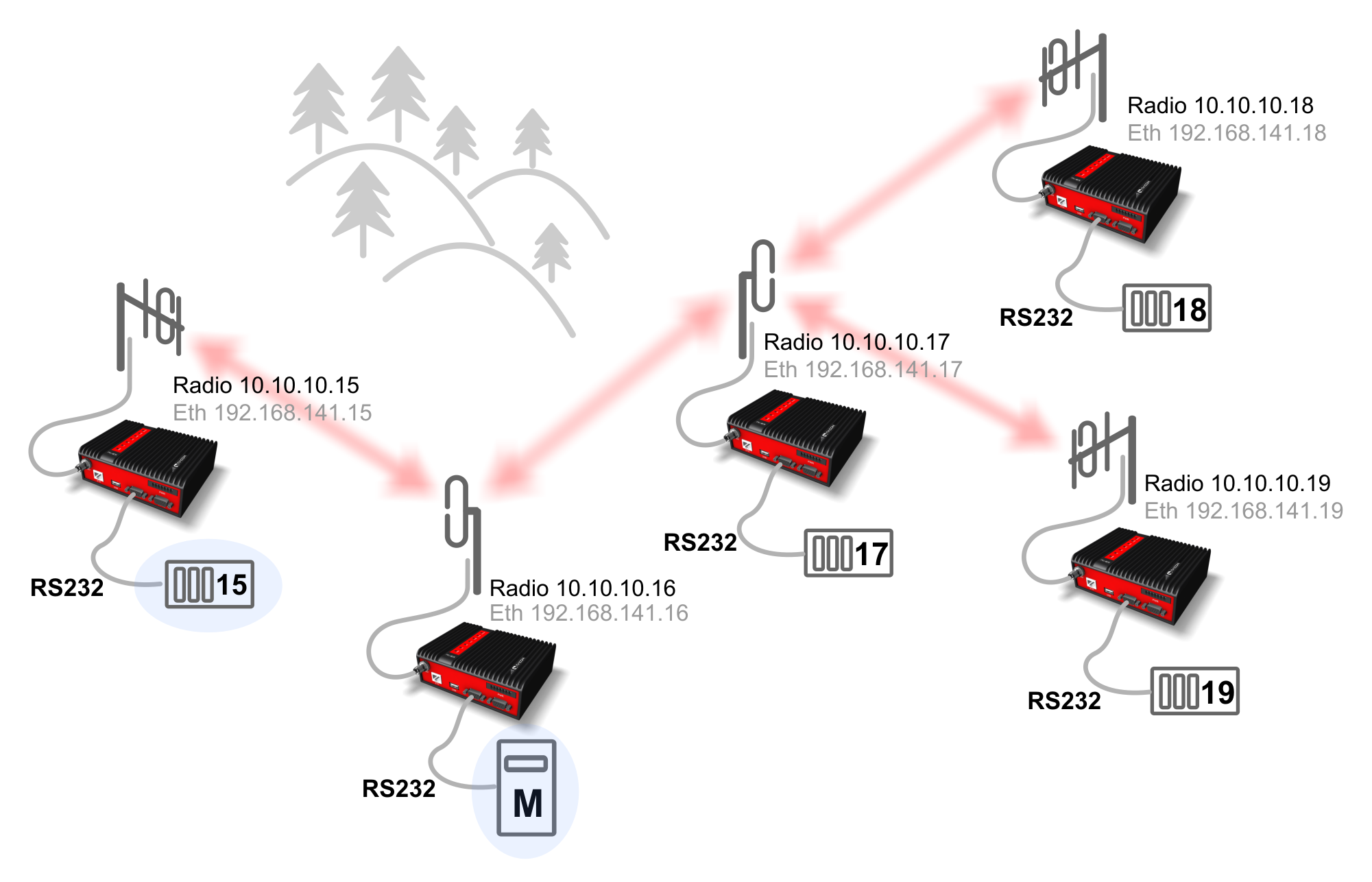
Every RipEX radio modem has two network interfaces, and hence two IP addresses. First is the Ethernet interface, second the radio interface. Serial interfaces are defined by their UDP port and are shared for the entire RipEX modem; as a result both RipEX IP addresses can be used to access them (both IP addresses work equally well).
The destination IP address of a packet received via the serial interface is determined inside the radio modem from the “SCADA address” depending on the protocol used, either using a mask or table (see RipEX manual, Adv. config., Protocols). The source IP is generated similarly.
If all devices are connected to RipEX’s via serial interface, it is helpful to only use the radio IP addresses for translation and routing of data. Ethernet IP addresses may be assigned randomly (you could keep their defaults, however we recommend setting Ethernet addresses similar to radio IP addresses to keep things organised). Remote service access over the radio channel is also possible via the IP addresses of the radio interface.
The following paragraph shows routing tables for individual radio modems which enable mutual communication between all devices. All destinations share the mask 255.255.255.255, i.e. 10.10.10.xx/32, interface Auto or Radio:
For 10.10.10.15
Destination via Gateway
10.10.10.17 via 10.10.10.16
10.10.10.18 via 10.10.10.16
10.10.10.19 via 10.10.10.16
For 10.10.10.16
10.10.10.18 via 10.10.10.17
10.10.10.19 via 10.10.10.17
For 10.10.10.17
10.10.10.15 via 10.10.10.16
For 10.10.10.18
10.10.10.15 via 10.10.10.17
10.10.10.16 via 10.10.10.17
10.10.10.19 via 10.10.10.17 (this record is only necessary if you require
                             communication between end devices 19 and 18)
For 10.10.10.19
10.10.10.15 via 10.10.10.17
10.10.10.16 via 10.10.10.17
10.10.10.18 via 10.10.10.17 (this record is only necessary if you require
                             communication between end devices 19 and 18)
To display the full routing table type “ip route show table normal” in CLI interface
For 10.10.10.19
10.10.10.15 via 10.10.10.17 dev radio  proto static
broadcast 10.10.10.0 dev radio  proto static  scope link  src 10.10.10.19
broadcast 10.10.10.255 dev radio  proto static  scope link  src 10.10.10.19
10.10.10.16 via 10.10.10.17 dev radio  proto static
10.10.10.18 via 10.10.10.17 dev radio  proto static
10.10.10.0/24 dev radio  proto static  scope link
192.168.141.0/24 dev eth0  proto static  scope link
default via 192.168.141.254 dev eth0  proto static
An example of a routing table on page Routing for 10.10.10.19
If SCADA device addresses can be chosen arbitrarily, routing can be significantly simplified when radio IP addresses can be grouped to subnets according to radio network layout.
One example of simplification is shown with repeaters connecting to separate subnets. The routing table can then contain a single record for all devices on the subnet.
In this example the first repeater connects to subnet 10.10.10.0/29, i.e. devices may have addresses from 10.10.10.1 to 10.10.10.6 (10.10.10.0 is reserved for the subnet, address 10.10.10.7 for broadcasting).
See e.g. http://www.subnet-calculator.com/subnet.php?net_class=A
For 10.10.10.254
Destination subnet via Gateway
10.10.10.0/29  via 10.10.10.2
10.10.10.8/29  via 10.10.10.9
10.10.10.16/29 via 10.10.10.17
For 10.10.10.2 (subnet 10.10.10.0/29)
10.10.10.8/29  via 10.10.10.254
10.10.10.16/29 via 10.10.10.254
For 10.10.10.3 and 10.10.10.4 and 10.10.10.5
10.10.10.248/29 via 10.10.10.2
10.10.10.8/29   via 10.10.10.2
10.10.10.16/29  via 10.10.10.2
For 10.10.10.9 (subnet 10.10.10.8/29)
10.10.10.0/29 via 10.10.10.254
10.10.10.16/29 via 10.10.10.17
For 10.10.10.10 and 10.10.10.11 and 10.10.10.12
10.10.10.248/29 via 10.10.10.9
10.10.10.0/29   via 10.10.10.9
10.10.10.16/29  via 10.10.10.9
For 10.10.10.17 (subnet 10.10.10.16/29)
10.10.10.0/29  via 10.10.10.254
10.10.10.8/29 via 10.10.10.9
For 10.10.10.18 and 10.10.10.19 and 10.10.10.20
10.10.10.248/29 via 10.10.10.17
10.10.10.0/29   via 10.10.10.17
10.10.10.8/29   via 10.10.10.17
The BDP must be configured as a STAR topology with up to 1 repeater for any remote. I.e. It is not possible to configure RipEX 10.10.10.15 as a Base station, because remote RipEX units 10.10.10.18 and .19 would go over two repeaters (3 hops). For this topology, RipEX 10.10.10.16 or .17 could be used as a Base station (up to 2 hops to any remote unit). The example uses RipEX 10.10.10.16 as a Base station.
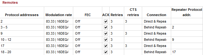
While using BDP, there is no need to configure any Routing in the Base or Terminal RipEX modem. Everything is set in the Base Settings menu. See the Base station Protocol configuration below:
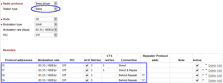
Remote unit 15 – this unit is reachable directly (one hop)
Remote unit 17 – this unit is reachable directly (one hop) AND is used as a repeater for other remote units
Remote units 18 and 19 – both units are reachable via the Repeater unit (17)
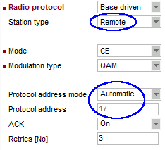
All remote units have the same configuration except the Radio/ETH IP address. The Protocol address equals the last digit of the Radio IP address and thus, “automatic” protocol address can be used. There is no need to configure any routing, everything is managed by the rules in the Base station (no matter if the remote unit is the repeater or simple terminal).
| Important | |
|---|---|
This configuration enables the communication between the Base station and all Remote units (terminals). If the communication among individual remote units is required, the Routing rules must be added in the Routing menu of all Remote units. All the static routes will use the Base Radio IP as a gateway, because all data must go through this Base station (not directly Remote to Remote as in the Flexible mode!). E.g. See the RipEX 10.10.10.19 Routing table: |
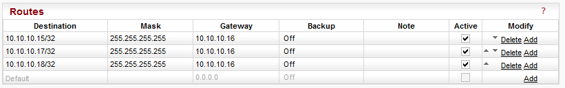
| Note | |
|---|---|
For example the communication between RipEX 10.10.10.19 and 10.10.10.18 would not only go via Repeater 10.10.10.17, but also via the Base station. Prefer the Flexible mode in case that a lot of remote to remote communication is required and higher jitter or lower payload bitrate is not an issue for your application. |
The following example explains the second scenario from the 1.1.1 Chapter, but configured using BDP.
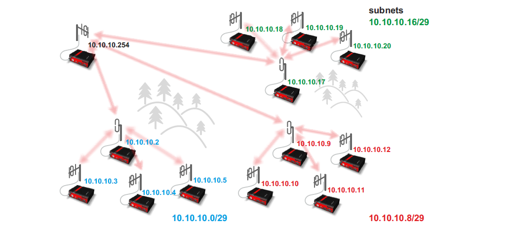
In this topology, the Base station can have just one rule to a group of remote units behind a particular repeater instead of configuring them separately. See the Base station configuration:
For each /29 subnet, we have two rules. One rule for the repeater itself and then a group of remote units reachable via this repeater.
All the remotes have the same configuration as in the previous example, just automatic Protocol address based on the last digit of the Radio IP. No routing required.