This chapter is identical with the content of Helps for individual menu.
Generally
RipEX can be easily managed from your computer using any web browser (Mozilla Firefox, Microsoft Internet Explorer, etc.). If there is an IP connection between the computer and the respective RipEX, you can simply enter the IP address of any RipEX in the network directly in the browser address line and log in. However it is not recommended to manage an over-the-air connected RipEX in this way, because high amounts of data would have to be transferred over the Radio channel, resulting in quite long response times.
When you need to manage an over-the-air connected RipEX, log-in to a RipEX, which your computer is connected to using either a cable (via LAN) or a high speed WAN (e.g. Internet). The RipEX which you are logged-in to in this way is called Local. Then you can manage any remote RipEX in the network over-the-air in a throughput-saving way: all the static data (e.g. Web page graphic objects) is downloaded from the Local RipEX and only information specific to the remote unit is transferred over the Radio channel. RipEX connected in this way is called Remote.
When in Router mode, the IP address of either the Radio or Ethernet interface in the remote unit can be used for such remote management. IP routing between source (IP of ETH interface in Local RipEX) and destination IP (either Radio or ETH interface in Remote RipEX) has to exist.
When in Bridge mode, IP addresses of Ethernet interfaces are used for both the Local and Remote units. Be careful, each RipEX MUST have its unique IP address and all these IP addresses have to be within the same IP network (defined by the IP Mask) when remote management is required in Bridge mode.
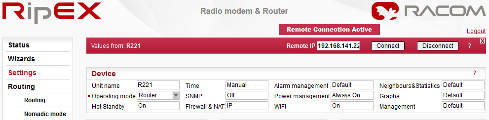
Values from
The Unit name (Settings/Device/Unit name) of the RipEX from which data is currently displayed and which is currently managed.
Remote IP
IP address of the remotely connected RipEX. After filling-in the Connect button shall be pressed.
Connect
Action button to connect to the remote RipEX, which is specified by the IP address in the Remote box. The Unit name in “Values from” box is changed accordingly afterwards.
Disconnect
When a Remote RipEX is successfully connected, the Disconnect button shows up. When the Disconnect process is executed, the Local RipEX (IP address in the Local box) can be managed and the Unit name in the “Values from” box changes accordingly.
Logout
Use the Logout link in the top right corner of the screen to logout the current user from the Local unit.
Web browser tab description
To facilitate management of multiple RipEX units at the same time, Web Browser tab names change dynamically.
The tab name contains:
IP address
RipEX Ethernet interface IP address or IP address if connected via IP tunnel
UDP port number if connected via IP tunnel
“>” mark when Fast remote connection is used (optional)
/Menu name “Unit name”
Device, Radio, ETH&COM
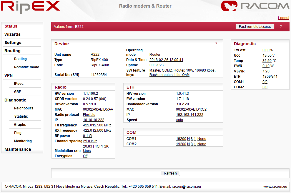
This part of Status page displays basic information about the RipEX (e.g. Serial No., MAC addresses, HW versions etc.) and overview of its most important settings. Configurable items are underlined and one click can take you to the respective Settings menu.
Diagnostic
The current state of Watched values is displayed in the Diagnostic part of the Status page. Watched values are values of parameters, which are continuously monitored by RipEX itself.
On-line help for each individual item is provided by balloon tips (when cursor is placed over an item name). When an item goes red, it means that the item is monitored for alarm and its value is in the alarm range (see Settings/Device/Alarm management)
– complete refresh of displayed values is performed.
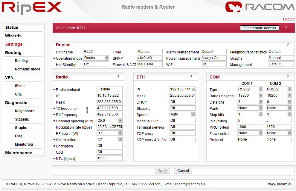
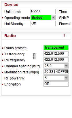
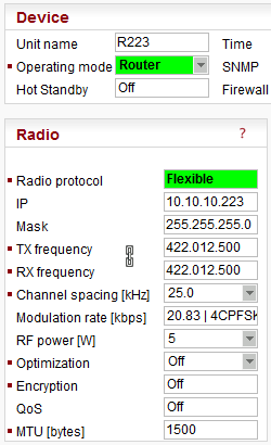
Device menu contains the following sections:
Default = NoName
Each Unit may have its unique name – an alphanumeric string of up to 32 characters. UTF8 is supported. Following characters are not allowed:
” (Double quote)
` (Grave accent)
\ (Backslash)
$ (Dollar symbol)
; (Semicolon)![[Important]](/images/radost/images/icons/important.png)
Important Unit name is solely for the user’s convenience, no DNS (Domain Name Server) is used in the RipEX network.
List box: Bridge, Router
Default = BridgeOperating mode defines whether the RipEX unit acts as a simple transparent device (Bridge mode) or Ethernet router (Router mode).
Bridge mode is suitable for Point-to-Multipoint networks, where Master-Slave application with polling-type communication protocol is used. RipEX in Bridge mode is as easy to use as a simple transparent device, while allowing a reasonable level of communication reliability and spectrum efficiency in small to medium size networks.
In Bridge mode, the protocol on the Radio channel does not have collision avoidance capability. There is CRC check of data integrity, i.e. once a message is delivered, it is 100% error free.
All the messages received from user interfaces (ETH&COM) are immediately transmitted to Radio channel, without any checking or processing.
ETH: The whole network of RipEX units behaves like a standard Ethernet network bridge, so the Ethernet interface IP address itself is not significant. Each ETH interface automatically learns which devices (MAC addresses) lie in the local LAN and which devices are accessible via the Radio channel. Consequently only the Ethernet frames addressed to remote devices are physically transmitted on the Radio channel. This arrangement saves RF spectrum from extra load which would otherwise be generated by local traffic in the LAN (the LAN to which the respective ETH interface is connected).
COM1, COM2: all frames received from COM1(2) are broadcast over Radio channel and transmitted to all COM ports (COM1 as well as COM2) on all units within the network, the other COM on the source RipEX excluding.
Router mode is suitable for Multipoint networks. Two different Radio protocols (Flexible and Base driven) are available to offer best performance dependent on type of application. These protocols can transmit both unicast and broadcast frames. They have collision avoidance capability, use frame acknowledgement and retransmissions, a CRC check to guarantee data delivery and integrity, even under harsh interference conditions on the Radio channel.
RipEX works as a standard IP router with 2 independent interfaces: Radio and ETH. Each interface has its own MAC address, IP address and Mask.
IP packets are processed according to the Routing table. There is also a possibility to set a router Default gateway (applies to both interfaces) in the Routing table.
The COM ports are treated in the same way as router devices, messages can be delivered to them as UDP datagrams to selected port numbers. Destination IP address of COM port is either the IP of ETH or the IP of Radio interfaces.
When RipEX unit is used in RipEX-HS and Hot Standby is “On” there are some limitations with it. Specifically, CD pin on COM1 and HW alarm Input and Output are used internally and not available to the user. Neither Save nor Sleep modes can be activated. Please refer RipEX-HS User manual.
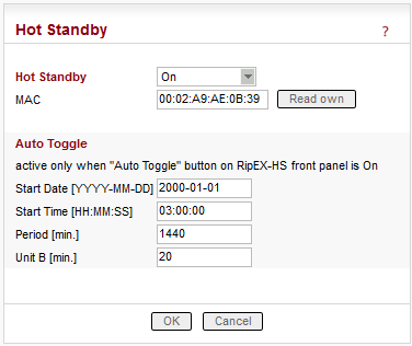
All settings below are valid only for RipEX units in RipEX-HS equipment, where two units in Hot Standby mode are running. Both units MUST have the same settings! Only Unit names should be different as this parameter is used in SNMP to recognize the sender of SNMP Notifications. In order to ensure that the settings of both units are identical, it is recommended to set unit “A”, thereafter save its settings into a file (Maintenance/Configuration/Save to file) and use these settings for unit “B”. (Maintenance/Configuration/Restore/File path/Upload) Finally, a unique Unit name should be assigned to Unit B.
List box: Off, On
Default = OffWhen “On”, HW switching from RipEX unit “A” to RipEX unit “B” is performed based on the HW Alarm Output settings in Settings/Alarm management. RipEX “A” is the primary unit, , Unit “B” is activated if there is HW alarm on unit “A” or unit “A” power source is down or when Auto Toggle Period expired. When mentioned events passed, RipEX “A” goes to be active again.
MAC
Both units in RipEX-HS are using the same MAC addresses (MAC cloning). Whichever unit is active (either “A” or “B”), RipEX Ethernet interface will use this MAC address. This MAC address has to be unconditionally set to the same value in both units used in RipEX-HS. Otherwise, the switching between units will not function properly.– it is possible to download the MAC address of this unit. The value in the second unit has to be manually set to the same value then
Auto Toggle mode
When Auto Toggle mode is On (HW button on front panel), controller automatically switches-over to RipEX “B”, even if “A” doesn’t have any alarm and uses “B” for a set time in order to confirm that RipEX “B” is fully ready-to-operate.Start Date [YYYY-MM-DD]
Fill in the Date in the required format when Auto Toggle mode starts.Start Time [HH:MM:SS]
Fill in the Time in the required format when Auto Toggle mode starts on “Start Date” day.Period [min.]
Minimum value 60 min.
Within this period units “A” and “B” will change their activities over. Unit “A” starts to operate at “Start Date and Time”. When “Period” minus “Unit B” time expires, controller switches to unit “B”.Unit B [min.]
Minimum value 5 min.
Time when unit “B” will be active within “Period”. It has to be shorter than Period by 5 min.
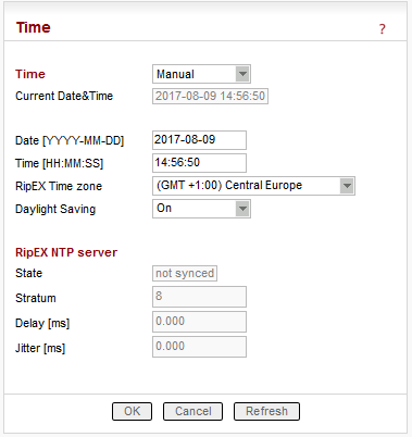
List box: Manual, NTP
Default = ManualInternal calendar time of RipEX can be set manually or synchronized via NTP (Network Time Protocol).
Manual
RipEX internally uses the Unix epoch time (or Unix time or POSIX time) – the number of seconds that have elapsed since January 1, 1970. When RipEX calendar time is set, the Unix epoch time is calculated based on filled in values (Date, Time) and the time zone, which is set in operating system (computer), where the browser runs.
Information about the actual date and time in the RipEX
Fill in Local Date in required format
Fill in Local Time in required formatRipEX Time zone
Select RipEX Time zone from list box.
Default = (GMT +1:00) Central Europe
This time zone is used for conversion of internal Unix epoch time to ‘human readable date&time’ in RipEX logs.
List box: On, Off
Default = On
If On, Daylight saving is activated according the respective rules for selected RipEX Time zone.
Internal calendar time in RipEX is synchronized via NTP and RipEX also acts as a standard NTP server simultaneously.
Information about the actual date and time in RipEX
List box: NTP server, Internal GPS
Default = NTP server– The source of time is a standard NTP server. This server can be connected either via the Ethernet interface or over the Radio channel (any RipEX runs automatically as a NTP server).
– The source of time is the internal GPS. In this case only RipEX Time zone and Daylight saving parameters below are active.
Default = empty
IP address of the NTP server, which provides Time source. Date and Time will be requested by RipEX from there. More NTP servers can be configured, the more servers, the better time accuracy. If the Time source is a RipEX over Radio channel, only one source server is recommended, since the Radio channel could be overloaded.
List box: 1min to 2h 17min
RipEX polls the source server in order to synchronize itself in the set period or later.RipEX Time zone
Select RipEX Time zone from list box.
Default = (GMT +1:00) Central Europe
This time zone is used for conversion of internal Unix epoch time to “human readable date&time” in RipEX logs..
List box: On, Off
Default = On
If On, Daylight saving is activated according the respective rules for selected RipEX Time zone.
RipEX NTP server
Information about the status of internal NTP server in the RipEX
State
not synced – not synchronized
synced to GPS – synchronized to internal GPS
synced to NTP – synchronized to NTP server
Stratum
1 to 16 (1=the best, 16=the worst, 8=when internal time in RipEX is set manually)
The stratum represents the quality and accuracy of time, which the NTP server provides.Delay [ms] This is the delay of packet (1/2 round trip time), which RipEX received from the NTP server while asked for synchronization. This delay is compensated in the RipEX NTP server.
Jitter [ms]
The Jitter of received times when RipEX asked for time synchronization from NTP server(s).
You can read more about SNMP in RipEX (MIB table description incl.) in RipEX application note “SNMP”.
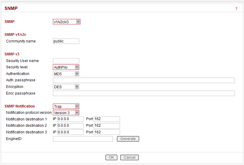
List box: Off, v1/v2c/v3, v3 only
Default = OffWhen enabled, RipEX works as a standard SNMP agent, i.e. it responds to “SNMP GET Request” packets received from even several SNMP managers on any of its IP addresses. It transmits SNMP Traps or SNMP Informs as per its configuration (Settings/Device/Alarm management or Routing/Backup).
The “v3 only” option can be enabled if the higher security is required.
SNMP v1/v2c
Community name
Default = public
This string is used for authentication with SNMP manager. Max. length is 32 chars. Following characters are not allowed:” (Double quote)
` (Grave accent)
\ (Backslash)
$ (Dollar symbol)
; (Semicolon)
(Space)
When there is not any char. filled, default value (public) is used.
SNMP v3
Security User name
This User name is used for authentication with SNMP manager. Max. length is 32 chars. Following characters are not allowed:” (Double quote)
` (Grave accent)
\ (Backslash)
$ (Dollar symbol)
; (Semicolon)
(Space)
Security level
List box: NoAuthNoPriv, AuthNoPriv, AuthPriv
Default = NoAuthNoPriv
Required SNMP communication security level:NoAuthNoPriv – Communication without authentication and privacy.
AuthNoPriv – Communication with authentication and without privacy. The “Authentication” parameter defines algorithm used for Authentication.
AuthPriv – Communication with authentication and privacy – encryption. The “Encryption” parameter defines algorithms used for encryption to assure the data privacy.
Authentication
List box: MD5, SHA
Default = MD5
The algorithm used for Authentication.Auth. passphrase
The authentication passphrase is entered as a password. Max. length is 128 characters. Empty password is not allowed.
Following characters are not allowed:” (Double quote)
` (Grave accent)
\ (Backslash)
$ (Dollar symbol)
; (Semicolon)
(Space)
Encryption
List box: AES, DES
Default = DES
The algorithm used to encrypt the data.Encr. passphrase
The encryption passphrase is entered as a password. Max. length is 128 characters. Empty password is not allowed.
Following characters are not allowed:” (Double quote)
` (Grave accent)
\ (Backslash)
$ (Dollar symbol)
; (Semicolon)
(Space)
SNMP Notification
List box: Off, Trap, Inform
Default = OffThe SNMP Notification can be activated. The SNMP Trap or SNMP Inform can be used to notify the remote management station(s) of unit alarms. The unit alarms are generated according to the settings in Alarm management (Settings/Device/Alarm management or Routing/Backup). The SNMP Notification (Trap or Inform) is sent both when a parameter value exceeds the alarm threshold and when it returns back within its ‘normal’ range. The Trap/Inform OID is the same, the information whether it is alarm activation or deactivation is given in the Trap/Inform data.
SNMP Trap – notification from the unit to the management
SNMP Inform – acknowledged notification from the unit to the managementNotification destination 1
IP address and Port where SNMP Notification (Trap or Inform) messages are sent. Default Port is 162, however it can be changed. IP 0.0.0.0 means, that SNMP Trap or Inform is not sent.Notification destination 2, 3
SNMP Notification (Trap or Inform) messages can be sent simultaneously up to three different destinations.
Inform repeats
Default: 3
SNMP Inform message is repeated multiple times until it is acknowledged or maximum number of repeats is reached.
See “Inform timeout” description for further information.Inform timeout [s]
Default = 10 sec. Range 0.1-20 [sec]
The SNMP Inform message is repeated when not acknowledged during “Inform timeout” period and when the number of “Inform repeats” has not been reached.
The “Inform repeats” and “Inform timeout” must be set in accordance with the real network latency between unit and management station. The unacknowledged SNMP Inform consumes system resources – for that reason the maximum number of concurrent unacknowledged SNMP Inform messages is 16 (for each “Notification destination”).
Firewall
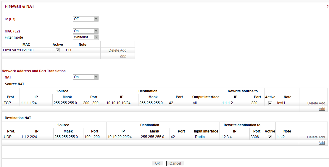
IP (L3)
List box: Off, On
NOTE: The L3 Firewall may be activated in both the Router and Bridge modes.
Default = OffIf “On“, a standard Layer 3 Linux firewall is activated.
Port – a range of port numbers can be entered. E.g. 2000-2120.
Connection state – state-firewall active only for TCP protocol.
New – relates to the first packet when a TCP connection starts (Request from TCP client to TCP server for opening a new TCP connection). Used e.g. for allowing to open TCP only from RipEX network to outside.
Established – relates to an already existing TCP connection. Used e.g. for allowing to get replies for TCP connections created from RipEX network to outside.
Related – a connection related to the “Established” one. e.g. FTP typically uses 2 TCP connections – control and data – where data connection is created automatically using dynamic ports.
NOTE 1:
L2/L3 firewall settings do not impact the local ETH access, i.e. the settings never deny access to a locally connected RipEX (web interface, ping, …).NOTE 2:
Ports 443 and 8889 are used internally for service access. Exercise caution when making rules which may affect datagrams to/from these ports in L3 Firewall settings. Management connection to a remote RipEX may be lost when another RipEX acts as a router along the management packets route and port 443 (or 8889) is disabled in firewall settings of that routing RipEX (RipEX uses iptables “forward”). When this happens, you have to use the Reset button on the bottom side of the misconfigured RipEX (keep it pressed for 15 sec.) in order to set Default access. It restores the default Ethernet IP, default password, sets the L3 Firewall to Off, sets ARP proxy&VLAN settings to Off and Ethernet speed to Auto.NOTE 3:
L3 Firewall settings do not impact packets received and redirected from/to Radio channel. The problem described in NOTE 2 will not happen when the affected RipEX router is a radio repeater, i.e. when it uses solely the radio channel for both the input and output.MAC (L2)
List box: Off, On
Default = OffIf “On” and when in the Router mode, simplified Layer 2 Linux firewall is activated:
Filter mode
List box: Blacklist, Whitelist
Default = BlacklistBlacklist
The MAC addresses listed in the table are blocked, i.e. all packets to/from them are discarded. The traffic to/from other MAC addresses is allowed.Whitelist
Only the MAC addresses listed in the table are allowed, i.e. only packets to/from them are allowed. The traffic to/from other MAC addresses is blocked.
If “On” and when in the Bridge mode, a standard Layer 2 Linux firewall is activated.
Protocol
List box: possible values
Default = AllAll – Ethertype is not checked, i.e. no packets are selected by the filter. addresses is allowed.
Manual – set 2 octets of Ethertype (in Ethernet frame) which are selected by the filter.
Not VLAN – only frames which are not embedded in VLAN are selected by the filter.
All VLAN – only VLAN frames are selected by the filter.
IPv4 – only IPv4 frames are selected by the filter.
IPv6 – only IPv6 frames are selected by the filter.
ARP – only ARP frames are selected by the filter.
LENGTH – only Ethernet frames from obsolete IEEE 802.3 Ethernet are selected by the filter.
VLAN
Default = None
This VLAN filter supersedes settings in Protocol. Frames with this ID of the 1st level VLAN will be selected by the filter.NOTE: When VLAN field is set, all settings in Protocol are applied to frame embedded in VLAN (Ethertype of the 2nd level).
Network Address and Port Translation
NAT Basic Description
Network address translation, or its extended version Network Address and Port Translation (NAPT) is a technique in which port numbers and private Internet Protocol (IP) addresses are mapped from multiple internal hosts to one public IP address.
Source NAT (SNAT) changes the source address and/or port of the outgoing connection. The returning packets are modified in the opposite way.
Example:
UDP SNAT
                              to:        192.168.169.169:6667
(Source IP addr: source port / destination IP addr. : destination port)
Outgoing packet:    192.168.1.1:1024
                                 / 192.168.169.250:8000
after SNAT: 192.168.169.169:6667/ 192.168.169.250:8000Returning packet: 192.168.169.250:8000/ 192.168.169.169:6667after modification: 192.168.169.250:8000/ 192.168.1.1:1024
Source NAT is performed on packets leaving the device. It takes place after routing and filtering in the firewall.
Destination NAT (DNAT) changes the destination address and/or port of the incoming connection. The returning packets are modified in the opposite way.
Example:
UDP DNAT
                              to:        192.168.169.250:8000
Incoming packet: 192.168.1.1:1024 / 192.168.1.2:18000after DNAT: 192.168.1.1:1024 / 192.168.169.250:8000Returning packet: 192.168.169.250:8000/ 192.168.1.1:1024after modification: 192.168.1.2:18000 / 192.168.1.1:1024
Destination NAT is performed on packets entering the device. It takes place before routing and filtering in the firewall.
Configuration
NAT
List box: Off, On
Default = Off
Enabling/disabling modification of incoming and/or outgoing connections according to NAT rules.Source NAT
Source NAT rules. The source packet IP address and/or Port is modified as a result of this function. The rules order is important – rules are actioned sequentiallyProt.
List box: All, ICMP, UDP, TCP, GRE, ESP
Default: All
IP Protocol to be affected by this rule.Source
This group of parameters defines rules based on the original packet source.IP
Default = 0.0.0.0/0
The original source of connections affected by the rule – defined by source IP address and length of a compared prefix.MASK
Default = 0 [0 = all ports, 65535 = Max]
The original source of connections affected by the rule – defined by source IP address mask.Port
Default = 0 [0 = no modification, 65535 = Max]
Source port. The Port rule is valid only for TCP and UDP Protocols.Destination
This group of parameters defines rules based on the original packet destination.
All the parameters – IP, Mask and Port – have similar meanings to the Source parameters.Output interface
List box: All, Radio, ETH
Default = All
Interface used by the connection to leave the unit.Rewrite source to
This group of parameters describes how to modify the connection source.IP
Default = 0.0.0.0
New source IP address. It is not modified if set to “0.0.0.0”.Port
Default = 0 [0 = no modification, 65535 = Max]
New source port. The Port rule is only valid for TCP and UDP Protocols.Active
You may tick/un-tick each rule in order to make it active/not active.Note
You may add a note to each rule with comments up to 16 characters in length (UTF8 is supported) for your convenience.
Characters not allowed:” (Double quote)
` (Grave accent)
\ (Backslash)
$ (Dollar symbol)
; (Semicolon)
NOTE: An Active rule with no Rewrite source to parameters assigned (both IP and Port in default value: 0.0.0.0 and 0) is not allowed.
Destination NAT
Destination NAT rules. The packet destination IP address and/or Port is modified as a result of this function. The rules order is important – rules are actioned sequentially.
The Prot., Source, Destination, Active and Note parameters have the same meaning as in Source NAT.Input interface
List box: All, Radio, ETH
Default = All
Interface used by the connection to enter the unitRewrite destination to
This group of parameters describes how to modify the connection destination.IP
Default = 0.0.0.0
New destination IP address. It is not modified if set to “0.0.0.0”.Port
Default = 0 [0 = no modification, 65535 = Max]
New destination port. The Port rule is only valid for TCP and UDP Protocols.NOTE: An Active rule with no Rewrite destination to parameters assigned (both IP and Port in default value: 0.0.0.0 and 0) is not allowed.
WARNING: NAT configuration changes require station restart. The restart is initiated automatically when parameters are applied.
NAT diagnostics
Monitoring
SNAT rules are applied before the packet leaves the RipEX interface.
DNAT rules are applied after the packet has left the interface it arrived through.
Monitoring is processed inside the interface: SNAT will be monitored (SNAT rules were applied prior to monitoring) and DNAT will not be monitored (monitoring takes place prior to DNAT rules being applied).
NAT in relation to other RipEX services
GRE
Under normal circumstances the GRE is only limited for use with the primary ETH address or Radio address as the Peer address. Using the SNAT, the source address of the outgoing GRE packet can be modified. This makes it possible to use any IP address as the GRE Peer address.
Such a configuration can be used when combining GRE with Backup routes when one of the alternative backup paths is routed over the GRE. Backup routes use the primary ETH address together with its specific routing rule. This prevents GRE from using this address. The SNAT can solve such situations as described here.TCP Proxy
Source NAT rules. The source packet IP address and/or Port is modified as a result of this function. The rules order is important – rules are actioned sequentiallyTCP Proxy captures the TCP packets prior to DNAT rules being applied.
SNAT does not work correctly with TCP Proxy unpacked packets.
IPsec
DNAT rules can be used prior to packets entering the IPsec
SNAT rules can be used after packets leaving the IPsec
SNAT rules can be used before packets enter the IPsec (Output interface has to be set to “All”)
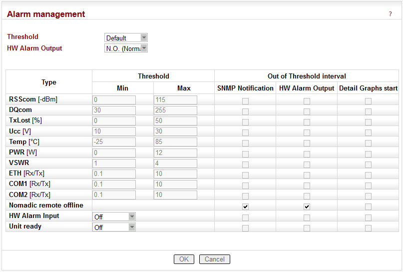
The average values of parameters listed in the table (Watched values) are continuously monitored. When any of them exceeds the respective threshold, the selected action(s) is(are) invoked.
The Hot Standby unit RipEX-HS uses the Alarm management for switching between unit A and B by means of signals of HW Alarm Output and HW Alarm Input. The Alarm Management Menu is slightly different (see description below).
![[Note]](/images/radost/images/icons/note.png)
Note At least 10 values have to be calculated into average before it is checked for the possible alarm. Since different values are sampled over different time periods, a range of results over time is required to obtain correct values:
Ucc, Temp – approx. 10 sec. after booting
PWR, VSWR – approx. 10 sec. after booting and after the first transmission
Others – approx. 200 sec. of respective communication
List box: Default, Manual
Default = DefaultDefault – Default (recommended) values are set and can not be edited.
Manual – Thresholds can be set manually. However, there are individual min. and max. threshold values for each item. When your settings are beyond these thresholds, the web interface will give you a warning and display the possible values.
HW Alarm Output
(not available for Hot Standby)
List box: Off, N.O. (Normally Open), N.C. (Normally Closed)
Default = OffIf “N.O.” or “N.C.”, the HW Alarm Output is active and its normal status (no alarm) is open or closed, respectively.
The HW Alarm Output is a pin (open n-p-n collector) on the screw terminal at the Power and Control connector on the front panel.
Type
Alarms are generated according to actual value of the following variables:
RSScom
Max value shall be set to the network design RSS value plus a fade margin (e.g. 80+20 dBm),
Min value can be 0 – stronger signals will typically not cause problems.DQcom
More significant communication troubles start with values less than 100; all values above 100 should be sufficient.RSScom and DQcom
together will indicate even partial damage or problems with the RipEX unit receiver parts or coaxial feedline cable or antenna. Equally, the problem could be on the transmitter part of RipEX unit, coaxial feedline cable or antenna of transmitter counterpart(s).TXLost
the value will indicate problems with packet deliveries to communicating parties. It is a percentage of lost packets on the Radio channel (acknowledge has not been received). Applicable only in Router mode. Exercise caution when setting this alarm. Keep in mind, that problems on counterpart unit(s) can also be reflected here. E.g. counterpart doesn’t receive packets or doesn’t transmit acknowledge.
Min value shall be set to 0, Max value to tens of % (e.g. 50).Ucc
actual value of the input power voltage of RipEX unit.Hot Standby – since power supply for RipEX units is controlled independently, this alarm is not recommended for switch-over to Standby unit. However, it can be used when an SNMP Notification informs about main power failure and switch to battery back-up. Min value shall be set to lower than 24.5, Max value to the maximum voltage limit for charging the battery (e.g. 29).
Temp
Internal temperature of RipEX unit.Hot Standby – the temperature of both RipEX units inside of RipEX-HS are likely to be the same, so it doesn’t make any sense to use this alarm for switch-over. However, this alarm can be used in case of hard duty cycle for switching between both units; Max value in such a case should be set to approximately 65.
PWR
This value shall be set to a value of power with a margin of ±25-30%. Alarm will be active in case of faulty transmitter part on the active RipEX.VSWR
Voltage Standing Wave Ratio measured on the antenna connector.Hot Standby – this value mainly indicates problems with antenna or antenna coaxial feed line cable. When RipEX-HS-xO (one antenna switched for A and B units), a switch-over to unit B will probably not help. Recommended values vary between 1 and 3.
ETH [Rx/Tx]
COM1 [Rx/Tx] COM2 [Rx/Tx]
These three values represent the No of received/transmitted packets on respective interfaces. They are mainly applicable for a polling type applications network. Each communication has one request and one reply ;the number of Rx and Tx packets should then be the same (Rx/Tx=1). These alarms should not be used for report by exception networks.HW Alarm Input
(not available for Hot Standby)
List box: Off, N.O. (Normally Open), N.C. (Normally Closed) Default = Off
If “N.O.” or “N.C.”, the HW Alarm Input is active and its normal status (no alarm) is open or closed, respectively.
An Alarm event is triggered when the HW Alarm Input changes its status from “Normal” to “Alarm”. Note that to “Close” the HW Alarm Input means connecting the respective screw terminal at the Power and Control connector on the front panel to the Ground terminal of the same connector.Hot Standby – uses the HW Alarm Input for switching between unit A and B.
HS active
(available only for Hot Standby)
Switching between unit A and B shall be indicated by SNMP or in a Graph.Unit ready
(not available for Hot Standby)
List box: Off, On
Default = Off
When “On”, the Hardware Alarm Output indicates the full functionality of the RipEX. The Hardware Alarm Output is only inactive when the RipEX is not powered or it is booting. When SNMP Trap and/or Detail Graphs are ticked in the Unit ready line, the respective action is taken after every Hardware Alarm Output state change (and also when the Apply button is activated after a reconfiguration). The “On” setting of this parameter disables any other assignment to the Hardware Alarm Output.Hot Standby – the “Unit ready” parameter cannot be activated in Hot Standby mode, since the Hardware Alarm Output controls the Hot Standby switch.
Above mentioned variables
should be individually defined thresholds and commands which will be executed in case of a deflection from the thresholds:
Threshold Min Max
When the value of a parameter goes under Min or over Max, the command within the ticked box will be executed.SNMP Notification
When ticked, the SNMP Notification message is sent when a parameter value exceeds the alarm threshold and again when it returns back within its ‘normal’ range. Remember to set the IP destination address(es) and port(s) for SNMP Notification messages in Settings/Device/SNMP.When even one SNMP Notification tick box is reconfigured in Alarm table, all SNMP Notifications for active alarms (out of thresholds) are re-sent with exception of the HW alarm input.
After reboot all SNMP Notifications for active alarms (out of thresholds) are re-sent, HW alarm input (HS active when Hot Standby is “On”) included.
When Statistic and Neighbours logs are cleared, RSScom, DQcom, ETH, COM1, COM2 alarms are cleared as well (e.g. the continual records will be cleared and the alarms will start from zero).
Hot Standby – when it is “On”, Alarm thresholds and HW alarm input are used internally for switching between unit A and B. The “HW alarm input” parameter is changed to “Hot Standby active”. Also, HW alarm output for Temperature is always On. Its thresholds can be Manually set in the interval of -50 to +90 °C (default -25 to +85 °C).
SNMP Alarm and Detailed Graphs tick boxes can be used for information about switching between unit A and B.
HW Alarm Output
The value is switched to On / Off (according to setting of parameter) when the Alarm status occurs.Hot Standby – the ticked parameters will cause switching between unit A and B when thresholds infringed.
Detail Graphs start
It has to be activated in Settings/Device/Graphs first.
When threshold of a ticked parameter is infringed the 20 previous and the following 40 points of all active graphs are saved into graph database, items for RSScom a DQcom will be executed for “Logged Neighbours IPs” written in menu Device/Graphs.
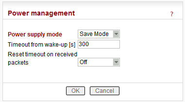
Power supply mode
List box: Always On, Save Mode, Sleep Mode
Default = Always OnAlways On
RipEX is always on, no special power saving modes are active.Save Mode
When a RipEX is switched to the SAVE mode, it can be in one of two states – the SAVE state or the ACTIVE state. In the SAVE state, the RipEX functionality is limited to listening to the Radio channel in order to minimize the power consumption (approx. 2W). In the ACTIVE state, the RipEX works normally, providing its full functionality (and consuming normal amounts of power).
Transitions between these states can be controlled by changes at the SI pin on the Power and Control connector, by receiving packets on the Radio channel and by values of the SAVE mode configurable parameters.
The transition from the SAVE to the ACTIVE state requires system boot and takes approximately 48 sec. The transition from the ACTIVE to the SAVE state takes about 4 seconds.SI hardware input (available from fw ver. 1.4.x.x)
When in the SAVE state, the RipEX wakes up (starts the transition to the ACTIVE state) after a rising edge is registered at the SI hardware input (after the respective pin connection to the ground has been opened). If a pulse is sent to the SI input (i.e. the falling edge follows the rising edge), it has to be longer than 50 msec.
When in the ACTIVE state, the transition to the SAVE state starts when a falling edge is registered at the SI hardware input (the respective pin has been connected to the ground). The falling edge triggers the transition only if the SI hardware input has been in the “high” state (opened) for 2 seconds at least during the ACTIVE state of the RipEX. Following the falling edge, the SI input has to stay in the “low” state (closed) at least for another 2 seconds.Radio channel
RipEX is listening on Radio channel in the Save mode while consuming 2 W. It is woken up when a packet is received over the Radio channel. However data from this first received packet is lost.Bridge mode: Any packet received on Radio channel wakes the unit up.
Router mode: RipEX is woken up when it receives a packet for its IP address. As “its IP” is considered any IP address configured in this RipEX (Radio, ETH, ETH Subnet, SLIP.) or any IP address routed through this RipEX. I.e. RipEX is woken up not only with packets which end in it, but also with packets which end in the connected device behind RipEX or which are relayed over the Radio channel (when this RipEX is configured as the Repeater for them).
When an unexpected reboot happens while in the ACTIVE state, the RipEX enters the ACTIVE state again and the “Timeout from wake-up” is reset. When a reboot happens while in the SAVE state, the RipEX enters the SAVE state immediately after the reboot.
When one of the configurable parameters is changed while the RipEX is in the ACTIVE state, the “Timeout from wake-up” is reset.Timeout from wake-up [s]
Default = 300 (min. 60, max. 64800)RipEX stays ACTIVE for the set time from the moment of its wake-up. When this timeout expires, the RipEX switches back to the SAVE state.
NOTE: It is possible to put RipEX into SAVE state anytime using the respective CLI command.Reset timeout on received packets
List box: On, Off
Default = OffIf “On”, the “Timeout from wake-up” is reset whenever a packet is received or transmitted over the Radio channel by the RipEX in the ACTIVE state. Consequently the RipEX stays in the ACTIVE state as long as it communicates over the Radio channel.
NOTE:
HW wake-up
With any fw version higher than or equal to 1.2.1.0 you can take a RipEX in Save state, cycle the power and during the boot-up (approx. 48 sec.) the LED Status starts to flash quickly in green for approx. 10 sec. When Reset button is pressed for approx. 1 sec. during that period of quick blinking, the Power supply mode is set to Always On and the unit can be accessed in the usual way (Ethernet or “X5” USB/ETH adapter)
Sleep Mode
Sleep Mode is controlled via the digital input on Power and Control connector. When the respective pin (SI) is grounded, RipEX goes to sleep and consumes only 0,07 W. The time needed for a complete wake-up from the Sleep mode is approx. 48 seconds (booting time).Timeout from sleep request [s]
Default = 10
RipEX remains On for the set time from the moment when the sleep input pin has been grounded. When SI pin on Power and Control connector is not-grounded for 1 sec. (or more) during this Timeout, the timeout is reset and starts again.
Note Save and Sleep modes are not available with the following configurations:
When Hot Standby is “On”
When Base driven protocol is used and Station type is “Base”
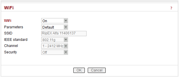
List box: Off, On
Default = OnWhen “On”, RipEX management can be executed over WiFi using the W1 – WIFI/USB adapter from RipEX accessories. This equipment must be plugged into RipEX USB interface. You just switch on WiFi in your device (notebook, tablet, smartphone…) and connect it to the RipEX WiFi network. Your device will get its IP settings from the RipEX built-in DHCP server. Then type https://10.9.8.7 in your browser address line and you will be connected to RipEX web pages.
NOTE:
DHCP in the W1 – WIFI/USB adapter provides max. 5 leases, so up to 5 devices can be connected to one RipEX via WiFi.Parameters
List box: Default, Manual,
Default = DefaultDefault – Default (recommended) values are set and can not be edited.
Manual – Values can be set manually.SSID
Default = RipEX + Unit name + S/N
An SSID (Service Set IDentifier) is a unique ID that consists of max. 32 characters and is used for naming wireless networks. When multiple wireless networks overlap in a certain location, SSIDs make sure that data gets sent to the correct destination. If empty, default value is filled.IEEE standard
There are different standards used for WiFi networks. RipEX supports some of them.
List box: possible values
Default = 802.11g802.11g
2.4 GHz frequency band, data speed up to 54 Mbps802.11n
802.11n is an advanced IEEE standard in the 2,4 GHz WiFi band. It was designed to improve on 802.11g in the amount of bandwidth (100 Mbps) supported by utilizing multiple wireless signals and antennas.
Channel
Your WiFi can work on different channels within 2,4 GHz band. When the selected channel is noisy, i.e. your WiFi connection is not stable, you can try another one.
List box: possible values
Default = 1Security
List box: possible values
Default = OffOff
If “Off”, WiFi is without any security, i.e. anybody can be connected and access your RipEX web pages.WPA2-PSK
A Short for WiFi Protected Access 2 – Pre-Shared Key. It is a method of securing your network using WPA2 with the use of Pre-Shared Key (PSK) authentication. To encrypt a network with WPA2-PSK you provide your router not with an encryption key, but rather with a plain-English passphrase between 13 and 64 characters long. Using a technology called TKIP (for Temporal Key Integrity Protocol), that passphrase, along with the network SSID, is used to generate unique encryption keys for each wireless client. And those encryption keys are constantly changed.WPA2 PSK Key – The string (13-64 characters) which is used for WPA2 encryption key generating.
The following characters are not allowed in the key:
” (Double quote)
` (Grave accent)
\ (Backslash)
$ (Dollar symbol)
; (Semicolon)
Note The WiFi connection needs to be reconnected when:
Unit restart occurs
The menu Settings/Device/WiFi is changed
The item Settings/Device/Unit name is changed
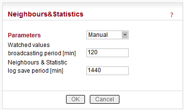
Parameters
List box: Default, Manual
Default = DefaultDefault
Default (recommended) values are set and can not be edited.Manual
Values can be set manually.There are 2 tables with diagnostic information in the main menu – Diagnostic/Neighbours, Diagnostic/Statistic. The Neighbours table displays Watched values from RipEX and from all its neighbours. (Neighbour = RipEX, which can be accessed directly over the radio channel, i.e. without a repeater). There is statistic information about the traffic volume in the Statistic table.
Default = 120 min, [0 = Off]
RipEX periodically broadcasts its Watched values to neighbouring units. The Watched values can be displayed in Graphs and Neighbours menu.
NOTE 1:
When Bridge mode is used, Watched values broadcasting creates collisions for user traffic. Be careful when using this feature.
NOTE 2:
When Router with Base driven Radio protocol is used:Watched values from Remote stations are only transmitted to the Base station.
Watched values from the Base station are broadcast to all Remote stations.
Repeater station receives Watched values from the Base station and from all Remote stations behind it.
Default = 1440 min (1 day) [10 – 7200 min]
This is the period, in which Neighbours and Statistics logs are saved in the archive and cleared and new logs start from the beginning.Note The history files are organized in a ring buffer. Whenever a new file is opened, the numbers of files are shifted, i.e. 0->1, 1->2, etc. There is a history of 20 log files available.
The Max value is 6.000.000 min. (more than 11 years) It used to be only 7.200 min. up to the 1.3.x.x fw version.
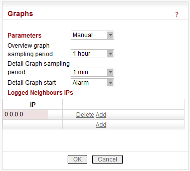
Parameters
List box: Default, Manual
Default = DefaultGraphs displays history of Watched values and history of some of the items from the Statistic table. Displayed values are stored in each RipEX including data from selected five neighbouring units. Neighbour = RipEX, which can be accessed directly over the Radio channel (not over Ethernet), i.e. without a repeater. The graph data is stored in files, each file contains 60 samples of all values. The sampling period can be configured. There are two types of graphs- Overview and Detail. Overview graphs cover a continuous time interval back from the present, they use relatively long sampling period. Detail graph is supposed to be used in case of a special event, e.g. an alarm, and the sampling period is much shorter.
Default = 0.0.0.0
Up to 5 IP addresses of neighbouring units can be set. (Neighbour = RipEX, which can be accessed directly over the radio channel, i.e. without a repeater). Watched values from these units are stored in the graph files and can be displayed afterwards.
List box: 1, 2, 4, 12 hours
Default = 12 hours
The 60 samples per graph file result in (depending on the sampling period) 60, 120, 240 or 720 hours in each file. There are 6 files available, so total history of saved values is 15, 30, 60 or 180 days. The Overview graph files are organized in a ring buffer. Whenever a new file is opened, the oldest one is replaced.
List box: 1, 5, 10, 20 min
Default = 1 min
The 60 samples per graph file result in 60, 300, 600, 1200 minutes in each file. There are 20 files available. They are organized in a ring buffer. When a new file is opened, the one with oldest data is replaced. The Detail graph files may not cover a continuous segment of history. See Detail graph start for details.
List box: No, Alarm, Single, Continual
Default = No
Detail graph data sampling is started based on selected event from list box:
No – Detail graph does not start.
Alarm – if a tickbox in Detail graph column (Settings/Alarm management) is checked, then the Detail graph file is stored in case of that alarm. Twenty samples prior the alarm event and forty samples after the alarm event are recorded. When another alarm occurs while a Detail graph file is opened, the sampling continues normally and no other file is opened.
Single – a single Detail graph file can be manually started. After Apply here, go to Diagnostic/Graph where a button is available
Continual – Detail graph files are periodically saved in the same way as Overview graph files are.
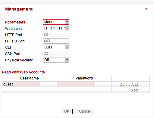
Parameters
List box: Default, Manual
Default = DefaultDefault
Default (recommended) values are set and can not be edited.Manual
Values can be set manually.
List box: HTTP+HTTPS, HTTPS, Off
Default = HTTP+HTTPS
Required protocol for configuration web page is set here. If “Off”, configuration web pages are inaccessible.
For HTTPS either (default) or your own SSL certificate can be used.
Default = 80
Just for information, can not be changed.
Default = 443
Just for information, can not be changed.
List box: SSH, Off
Default = SSH
Command Line Interface is accessible via the SSH protocol. If “Off”, CLI is inaccessible. The SSH keys are unique for each individual RipEX Serial number. The public key is downloaded in RipEX, for the private key kindly contact and provide the RipEX S/N.
Default = 22
Just for information, can not be changed.
List box: Off, On
Default = Off
When “On”, external flash disc access is disabled (It is not possible to download or upload the configuration automatically). When the HW reset button is pressed, “Total purge” instead of “Factory settings” is applied. The Total purge sets the very same settings as delivered from the factory. For details see Section 7.7.2, “Configuration”.
Read-only Web Accounts
The two different levels of unit administration privileges are supported:
user is not limited.
are limited to read only access. Only Status, Neighbours, Statistic and Graphs screens are available.
Use the “Logout” link in the top right corner of the screen to logout the current user.
Up to 10 different read-only users can be defined. Maximum length is 32 characters. Only characters a-zA-Z0-9_ are allowed.
Password length is at least 5 and maximum 32 characters long. Only characters a-zA-Z0-9.:_- are allowed.
There are 2 different Operation modes in RipEX: Bridge and Router with 3 different protocols on Radio channel: Transparent used in Bridge mode, Flexible and Base driven used in Router mode.

Radio channel protocols configuration differs for each of the protocols:
![]()
Radio menu contains the following main parts:
Common Radio protocol parameters
The parameters described in this section are same for individual Radio protocols.
There is only a link to them in description of the respective Radio protocol.*
** These items have to be set in accordance with the license issued by the respective radio regulatory authorityMode**
RipEX allows multiple settings of modulation parameters for every channel spacing to enable different regulations which apply in different countries to be met. Naturally different limits on transmitted signal parameters result in different Modulation rates.
The “Mode” menu conveniently groups the optimal settings for common internationally recognized standards. The detailed technical parameters for each setting can be found in the RipEX User manual.
List box: possible values
Default = CECE
Settings optimized for ETSI standards and similar.FCC
Settings suitable for countries which follow the U.S. government group of standards.
NOTE: CPFSK modulations have approx. 20% higher frequency deviation compared to CE, so the receiver sensitivity for the same modulation (data rate) is approx. 1-2 dB better.
Special settings for extra-restrictive regulations.
NOTE: In the 25 kHz channel spacing, the RipEX transmitted signal 16kHz bandwidth contains 99% of the total integrated power for transmitted spectrum according to ITU-R SM328 . This setting is required for 25 kHz channel spacing by authorities in Czech Republic.Unlimited
Full channel width used to achieve the maximum possible data rate.
Modulation type
List box: FSK, QAM
Default = FSKFSK
Suitable for difficult conditions – longer radio hops, non line of sight, noise / interferences on Radio channel…
NOTE: FSK belongs to the continuous-phase frequency-shift keying family of non-linear modulations. It is possible to use higher RF output power (up to 10 watts) for these types of modulation. Compared to QAM (linear modulations), FSK is characterized by narrower bandwidth, a lower symbol rate and higher sensitivity. As a result, the system gain is higher, power efficiency is higher, but spectral efficiency is lower.QAM
Suitable for normal conditions offering higher data throughput.
NOTE: QAM belongs to the phase shift keying family of linear modulations. Compared to FSK (non-linear modulations), QAM is characterized by wider bandwidth. RF output power is limited to max. 2 watts. The spectral efficiency is higher, power efficiency is lower and system gain is typically lower.
Modulation rate [kbps]**
List box: possible values
Possible values in list box are dependent on the Modulation type setting. The two highest rates for 25 and 50 kHz channel spacing are available only when the corresponding SW feature key is active (Either the 166/83 kbps key or the Master key).
Higher Modulation rates provide higher data speeds but they also result in poorer receiver sensitivity, i.e. reduced coverage range. Reliability of communication over a radio channel is always higher with lower Modulation rates.FEC
List box: possible values
Default = Off
FEC (Forward Error Correction) is a very effective method to minimize radio channel impairments. Basically the sender inserts some redundant data into its messages. This redundancy allows the receiver to detect and correct errors. The improvement comes at the expense of the user data rate. The lower the FEC ratio, the better the capability of error correction and the lower the user data rate. The User data rate = Modulation rate x FEC ratio.ACK
List box: On, Off
Default = On
This setting requires additional bandwidth to repeat corrupted frames.On
Each frame transmitted on Radio channel from this RipEX has to be acknowledged by the receiving RipEX, using the very short service packet (ACK), in order to indicate that it has received the packet successfully. If ACK is not received, RipEX will retransmit the packet according to its setting of Retries.
NOTE: The acknowledgement/retransmission scheme is an embedded part of the Radio protocol and works independently of any retries at higher protocol levels (e.g. TCP or user application protocol)Off
There is no requirement to receive ACK from the receiving RipEX. i.e. the packet is transmitted only once and it is not repeated.
Retries [No]
Default = 3 [0=Off, 15=Max]
When an acknowledge from the receiving RipEX is not received, the frame is retransmitted. The number of possible retries is specified.Advanced parameters
TX Buffer
The Radio protocol transmission buffer handles data waiting to be transmitted. Its size is defined by both the number of records (Queue length) and total storage space (Queue size) requirement. Records are held in a queue which is considered full, if either the Queue length or Queue size is reached. New incoming frames are not accepted when the queue is full.Queue length
Default = 5 [1 – 31]
Queue length dictates the maximum number of records held in the queue.Queue size [kB]
Default = 5 [1 – 48]
Queue size dictates the total size of all records that can be held in the queue.TX Buffer timeout
List box: Off, On
Default = Off
The frames waiting for transmission in the Radio protocol output frame queue will be discarded after the TX Buffer timeout expires. This parameter should be enabled for types of applications where sending old frames brings no benefit.
When the frame is discarded the event is recorded, both in the statistics (as “Rejected”) and in the monitoring (the respective frame is displayed with the “Tx buffer timeout” tag).TX Buffer timeout [s]
Default = 5 [0.01 – 150, Granularity 0.01s]
Radio protocol transmit buffer timeout. The “TX Buffer timeout” must be enabled for this parameter to be initiated.
Others
Radio ARP timeout [min]
Default = 1440 [1=Min, 3579=Max]
Each IP device refreshes its ARP records within some timeout. Because of that, the device transmits spontaneous ARP request packets to each IP address listed in its ARP table. That may generate unwanted collisions on Radio channel. Since Radio IP and MAC addresses are not changed during normal network operation, ARP table refreshing may be done in a long period (1440 min. = 1 day).
The RipEX spontaneously transmits an ARP reply packet after each reboot. The ARP reply packet transmission can be also invoked by executing Maintenance/Miscellaneous/BRC Radio MAC button.
ARP reply packet refreshes the respective records in neighbouring units. This is necessary e.g. when a RipEX unit has been replaced by a spare one with the same Radio IP address.
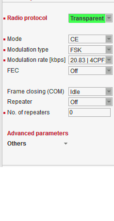
List box: Transparent, Flexible, Base driven
Possible values in list box are dependent on the Operating mode setting.Transparent //Operating mode = Bridge
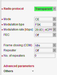
Bridge mode with Transparent Radio protocol is suitable for Point-to-Multipoint networks, where Master-Slave application with polling-type communication protocol is used. The Transparent protocol does not have collision avoidance capability. A CRC check of data integrity, ensures when a message is delivered, it is 100% error free. All messages received from user interfaces (ETH&COM) are immediately transmitted to the Radio channel, without any checking or processing.
Italicised parameters are described in Common parameters.Frame closing (COM1,2)
List box: Idle, Stream
Default = IdleIdle
Received frames on COM1 (COM2) are closed when gap between bytes is longer than the Idle value set in COM1,2 settings and transmitted to Radio channel afterwards.Repeater
List box: Off, On
Default = Off
Each RipEX may work simultaneously as a Repeater (Relay) in addition to the standard Bridge operation mode.
If “On”, every frame received from Radio channel is transmitted to the respective user interface (ETH,COM1,2) and to the Radio channel again.
The Bridge functionality is not affected, i.e. only frames whose recipients belong to the local LAN are transmitted from the ETH interface.
It is possible to use more than one Repeater within a network. To eliminate the risk of creating a loop, the “Number of repeaters” has to be set in all units in the network, including the Repeater units themselves.
Warning: Should Repeater mode be enabled “Modulation rate” and “FEC” must be set to the same value throughout the whole network to prevent frame collisions occurring.Number of repeaters
Default = 0
If there is a repeater (or more of them) in the network, the total number of repeaters within the network MUST be set in all units in the network, including the Repeater units themselves. After transmitting to or receiving from the Radio channel, further transmission (from this RipEX) is blocked for a period calculated to prevent collision with a frame transmitted by a Repeater. Furthermore, a copy of every frame transmitted to or received from the Radio channel is stored (for a period). Whenever a duplicate of a stored frame is received, it is discarded to avoid possible looping. These measures are not taken when the parameter “Number of repeaters” is zero, i.e. in a network without repeaters.
Stream
In this mode, the incoming bytes from a COM are immediately broadcast over the Radio channel. COM port driver does not wait for the end of a frame. When the first byte is coming from a COM, the transmission in the Radio channel starts with the necessary frame header. If the next byte arrives before the end of transmission of the previous one, it is glued to it and the transmission on the Radio channel continues. If there is a gap between incoming bytes, the byte after the gap is treated as the first byte and the process starts again from the beginning. Padding is never transmitted between block of bytes.
The receiving RipEX transmits incoming bytes (block of bytes) from the Radio channel to both COM ports immediately as they come.
When the ETH interface is used simultaneously (e.g. for remote configuration), it works as the standard bridge described above. ETH frames have higher priority, i.e. the stream from COM is interrupted by a frame from Ethernet.
Stream mode is recommended to be used for time-critical application only, when the first byte has to be delivered as soon as possible. However there is not any data integrity control. If the Baud rate of COM is significantly lower than the Modulation rate on the Radio channel, frames are transmitted byte by byte. If it is higher, blocks of bytes are transmitted as frames over the Radio channel.
NOTE: Stream mode can not be used when there is a Repeater in the networkAdvanced parameters
Others
TX Delay [bytes]
Default = 0 [0=0ff, 1600=Max]
Each packet is delayed before it is transmitted on Radio channel for time, which is equal to the time needed for transmission of the number of bytes set. This time depends on the set Modulation rate. E.g. if you want to delay all packets for time which equals the transmission time of a UDP packet with 150 user data bytes, you need to set 178 bytes (20B IP header, 8B UDP leader, 150B user data).
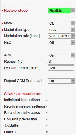
Flexible //Operating mode = Router
Router mode with Flexible protocol is suitable for Multipoint networks of all topologies with unlimited number of repeaters on the way, and all types of network traffic where Multi-master applications and any combination of simultaneous polling and/or report-by-exception protocols can be used.
Each RipEX can access the Radio channel spontaneously using sophisticated algorithms to prevent collisions when transmitting to the Radio channel. Radio channel access is a proprietary combination of CSMA and TDMA; the Radio channel is deemed to be free when there is no noise, no interfering signals and no frames are being transmitted by other RipEX stations. In this situation a random selection of time slots follows and a frame is then transmitted on the Radio channel.
Frame acknowledgement, retransmissions and CRC check, guarantee data delivery and integrity even under harsh interference conditions on the Radio channel
NOTE: The Flexible protocol was the only Radio protocol used in the RipEX with Router mode for fw ver. lower than 1.6.x.x (1.5.7.0).
Italicised parameters are described in Common parameters.RSS threshold [-dBm]
Default = 120
RSS (Received Signal Strength) limit for access to Radio channel. RipEX does not start transmitting when a frame is being received and the RSS is better than the set limit or when the destination MAC address of the frame is its own.Repeat COM Broadcast
List box: On, Off
Default = Off
If On, a broadcast originated on COM port (Protocol/Broadcast = On) in any remote unit and received by this unit on Radio channel is repeated to Radio channel.Advanced parameters
Individual link options
It is possible to set certain Radio protocol parameters individually for a specific radio hop. The Radio hop is defined by a record in the table. General settings as above are used for radio hops, which are not defined in this table.Counterpart Radio IP
Radio IP address of RipEX on the opposite site of radio hop.Note
You may add a note to each address with your comments up to 16 characters (UTF8 is supported) for your convenience. (E.g. ” Remote unit #1 ” etc.). Following characters are not allowed:
”(Double quote)
`(Grave accent)
\(Backslash)
$(Dollar symbol)
;(Semicolon)Active
You may tick/un-tick each line in order to make it active/not active.
Retransmission settings
An advanced user can modify the frame retransmission protocol parameters in this menu in order to optimize the network throughput under specific load. This menu is accessible only when parameter “ACK” is “On” and “Retries [No]” is greater than zero.The retransmission timeout is calculated as follows (see below for details):
Rt = Ft + [0..Mv] * Vt + Prog
Where:
Rt – Retransmission timeout
Ft – time defined by the “Fix timeout [bytes]”
Vt – time defined by the “Variable timeout [bytes]”
Prog – zero when
Mv – value
[0..Mv] represents a random number from sequence 0 to Mv (limiting values included).Progressivity
List box: Off, On
Default = Off
When On, the Prog value used in the formula above is calculated as follows:
Prog = Ft * (Nr – 1)
Ft – see above
Nr – the retransmission sequence number, e.g. Nr = 3 when the very same frame is to be retransmitted for the third time (Nr = 0 for the initial frame transmission)Fix timeout [bytes]
Default = 350 [10=Min, 10000=Max]
This part of the retransmission timeout is always included (see the formula above). The actual time equals the time needed for transmission of the number of bytes set. This time depends on the set Modulation rate. E.g. when the Fix timeout should equal the transmission of a UDP packet with 150 user data bytes, you need to set 178 bytes (20B IP header, 8B UDP leader, 150B user data).Variable timeout [bytes]
Default = 350 [10=Min, 10000=Max]
This part of the retransmission timeout is multiplied by an integer random number (see the formula above) and then included. The actual time is obtained in the same way as for the “Fix timeout [bytes]” above.Max Variable [No]
Default = 4 [0=Min, 15=Max]
This number defines the range from which the random integer number is chosen to multiply the Variable timeout (see the formula above).
Busy channel access
An advanced user can modify the RF channel access parameters in this menu. The explanations below assume general knowledge of collision-oriented MAC layers of layer 2 protocols.TX Delay [bytes]
Default = 0 [0=Off, 16000=Max]
The number of bytes set in this parameter define time period the same way as e.g. the “Fix timeout [bytes]” above. This time period is added to the normal access time (i.e. random number of slots, see below) whenever the RF channel is evaluated as busy in the moment the transmission is requested. Access to a free channel is not delayed.Slot length [bytes]
Default = 0 [0=Min, 250=Max]
Length of MAC layer access slot. The respective time period is calculated the same way as for the “Fix timeout [bytes]” defined above. When value of 0 (default) is set, the slot time is set to the shortest possible frame size.
WARNING: Sloth length significantly influences the network throughput under heavy load conditions. It MUST be set to the same value in every network member.Slots after RX [No]
Default = 4 [0=Min, 12=Max]
The range from which the random integer number is chosen to multiply the slot length in order to get the access time period. This value is used when the previous channel event was a data frame reception (by the same radio). Note that ACK is not considered a data frame.Slots after TX [No]
Default = 6 [0=Min, 12=Max]
The range from which the random integer number is chosen to multiply the slot length in order to get the access time period. This value is used when the previous channel event was a data frame transmission from the same radio. Note that ACK is not considered a data frame.Slots handicap [No]
Default = 0 [0=Min, 7=Max]
A fixed number which is always added to the random number of slots generated from the respective range (see above). The higher slot handicap a radio has, the lower chance to win the channel access competition it may stand.
NOTE: The maximum number of slots used to calculate the channel access period is 14. When the sum of the slot handicap and the generated random number exceeds 14, it is cut to that figure.
Collision prevention
This menu allows for setting up a prevention mechanism against application-driven collisions. Perfectly synchronized simultaneous transmission requests arriving to different radios in long enough intervals may always come in free channel conditions and consequently the zero access time period is applied, resulting in a “guaranteed” collision.
NOTE: These are not the “common” collisions taking place when RF channel is heavily loaded.Probability [%]
Default = 0 [0=0ff, 100=Max]
When a transmission request arrives in free channel conditions, a delay period defined below is applied with the probability set.Delay length [bytes]
Default = 10 [1=Min, 16000=Max]
This item is visible only when the “Probability” value (see above) is non-zero. The actual delay time period is calculated the same way as for e.g. the “Fix timeout [bytes]” item defined above. It is applied as the channel access period only when the RF channel is free (hence the normal channel access period would be zero). When the RF channel is busy, standard mechanism of random slotted access is used.
TX Buffer
Others
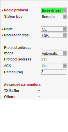
Base driven //Operating mode = Router
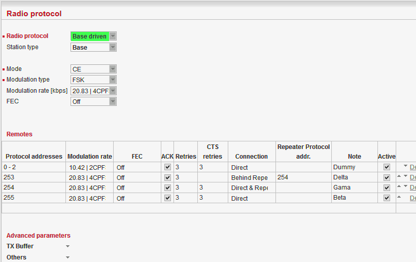
Router mode with Base driven protocol is suitable for a star network topology with up to 256 Remotes under one Base station. Each Remote can simultaneously work as a Repeater for one or more additional Remotes. This protocol is optimized for TCP/IP traffic and/or ‘hidden’ Remotes in report-by-exception networks when a Remote is not be heard by other Remotes and/or different Rx and Tx frequencies are used.
All traffic over the Radio channel is managed by the Base station. Radio channel access is granted by a deterministic algorithm resulting in collision free operation regardless of the network load. Uniform distribution of Radio channel capacity among all Remotes creates stable response times with minimum jitter in the network.
Frame acknowledgement, retransmissions and CRC check, guarantee data delivery and integrity even under harsh interference conditions on the Radio channel.
NOTE 1:
There is no need to set any routes in Routing table(s) for Remote stations located behind Repeater. Forwarding of frames from the Base station over the Repeater in either direction is serviced transparently by the Base driven protocol.
NOTE 2:
When Remote to Remote communication is required, respective routes via Base station have to be set in Routing tables in Remotes.Station type
List box: Base, Remote
Default = BaseBase
Only one Base station should be present within one radio coverage when Base driven protocol is used.
Italicised parameters are described in Common parameters.
Remotes
Radio protocol parameters for every Remote station must be configured in this table. Group(s) of remotes can be configured together if assigned within an interval of Protocol addresses.Protocol address
Protocol address [0 to 255] is the unique address assigned to each Remote and is only used by Base driven protocol. It is set in Remote unit in its Radio protocol settings. The default and recommended setting assigns Protocol address to be equal to the Radio IP last byte (Protocol address mode in Remote unit is set to Automatic then).
There are two possibilities to fill in the Protocol address in the table:
Note If you configure any Remote station Protocol addresses which are not present in the running network, radio channel access will be granted to them regularly resulting in lower total network throughput: Every address listed in this table will be taken into consideration when configuring radio channel access. It is possible to prepare configuration for an additional radio unit in the network if needed. The “Active” parameter (see below) within such a table record can be marked as not active. In this case, the record is never granted radio channel access.
Modulation rate
Set value is used in both directions from Base to Remote and from Remote to Base. If the Remote station is behind Repeater, set value is used for both radio hops: Base station – Repeater and Repeater – Remote.FEC
Set value is used in both directions from Base to Remote and from Remote to Base. If the Remote station is behind Repeater, set value is used for both radio hops: Base station – Repeater and Repeater – Remote.ACK
Set value is used in one direction from Base to Remote (Remote to Base direction is configured in Remote unit in its Radio protocol settings). If the Remote station is behind Repeater, set value is used for both radio hops: Base station – Repeater and Repeater – Remote.Retries
Set value is used in one direction from Base to Remote (Remote to Base direction is configured in Remote unit in its Radio protocol settings). If the Remote station is behind Repeater, set value is used for both radio hops: Base station – Repeater and Repeater – Remote.CTS Retries
Default = 3 [0=Off, 15=Max]
Based on sophisticated internal algorithm, Base station sends a CTS (Clear To Send) packet which allows Remote station to transmit. If the Remote station is connected directly to the Base station (not behind Repeater), and the Base station doesn’t receive a frame from the Remote station, the Base station repeats permission to transmit.Connection
List box: Direct, Direct & Repeater, Behind Repeater
Default = Direct
Type of radio connection between Remote and the Base station defines the position of the respective unit in the radio network topology:Direct
Remote station having direct radio communication with the Base station.Direct & Repeater
Remote station having direct radio communication with the Base station and acting as a Repeater.Behind Repeater
Remote station communicating with the Base station over a Repeater station. Max. one Repeater can be used between any Remote and the Base station. More than one Remote stations can be behind one Repeater.
Repeater Protocol address
If Remote station is ‘Behind Repeater’ type, Protocol address of the Repeater must be assigned.Note
You may add a note to each address with your comments up to 16 characters (UTF8 is supported) for your convenience. (E.g. ” Remote unit #1 ” etc.). Following characters are not allowed:
”(Double quote)
`(Grave accent)
\(Backslash)
$(Dollar symbol)
;(Semicolon)Active
You may tick/un-tick each line in order to make it active/not active
Advanced parameters
Others
Query timeout [s]
Default = 3 [1 – 31]
When any Remote doesn’t communicate with the Base within a Query timeout period, Base station transmits ‘query packet’ in order to find out whether this ‘non-communicating’ Remote has anything to send even if other Remotes have continuing data transfers.
NOTE: The Modulation rate and total number of Remotes should be considered when setting this parameter. If the Modulation rate is low and the network contains a large number of Remotes, the Query timeout must be long enough to allow a query packet to be sent to every remote within the network and also allow time for data transactions as well.Broadcast repeats
Default = 3 [0=Off, 15=Max]
Every broadcast is repeated a given number of times. Broadcast repeats = 0 turns off broadcast repetition. Broadcast frames aren’t acknowledged, hence the need for repetition.

Up to 256 Remote stations can be configured under one Base station. Any Remote station [stand-alone, repeater or behind a repeater] must also be configured in Base station/Radio protocol/Remotes.
If a frame needs to be routed from one Remote station to another Remote station, it must be routed through the Base station. Appropriate routing rules must be defined.
Italicised parameters are described in Common parameters.
Protocol address mode
List box: Automatic, Manual
Default = Automatic
Radio protocol address can be determined in two different ways:Automatic
Protocol address is the same as the last byte of Radio IP address.Manual
Protocol address is set up manually (see parameter Protocol address).
Protocol address
Default = 1 [0 – 255]
Can only be configured only when Protocol address mode is set to Manual.
The same Protocol address must be set in the Base station/Radio protocol/Remotes.Advanced parameters
IP*
Default = 10.10.10.169
IP address of Radio interfaceMask*
Default = 255.255.255.0
Network Mask of Radio interfaceTX frequency**
Transmitting frequency. Format MHz.kHz.Hz. Step 5 (for 25 kHz channel spacing) or 6.25 kHz (for 12.5 or 6.25 kHz channel spacing).
The value entered must be within the frequency tuning range of the product as follows:RipEX-135: 135-154 MHz
RipEX-154: 154-174 MHz
RipEX-300: 300-320 MHz
RipEX-320: 320-340 MHz
RipEX-340: 340-360 MHz
RipEX-368: 368-400 MHz
RipEX-400: 400-432 MHz
RipEX-432: 432-470 MHz
RipEX-470: 470-512 MHz
RipEX-928: 928-960 MHzRX frequency**
Receiving frequency, the same format and rules apply.
NOTE: By default, the TX and RX frequencies are locked together and change in one field is mirrored in the other. If clicked, the lock is removed and different TX and RX frequencies can be entered.Channel spacing [kHz]**
List box: possible values
Default = 25 kHz
The wider the channel the higher the possible Modulation rate.
NOTE: The 50 kHz channel spacing is available only for HW versions of Radio board higher than 1.1.90.0 or 1.2.50.0. See Status/Radio/HW version.RF power [W]**
List box: possible values
Default = 5 W
The range of values in the list box is limited to 2 W for high Modulation rates. 10 W is available only for lower Modulation rates (CPFSK) and only when the corresponding SW feature key is active.
NOTE: Max. RF power for RipEX-470 is 8 W. (Even if there was 10 W in list box for fw ver. 1.3.x.x and older)Optimization*
List box: On, Off
Default = Off
Optimization is applicable in Router mode for packets directed to Radio channel. It watches packets on individual radio links and optimizes both the traffic to the counterpart of a link and the sharing of the Radio channel capacity among the links.
On an individual link the optimizer supervises the traffic and it tries to join short packets when opportunity comes. However in case of heavy load on one link (e.g. FTP download) it splits the continuous stream of packets and creates a window for the other links. To minimize the actual load, Zlib compression (with LZ77 decimation and Huffman coding) and other sophisticated methods are used.
There is also a “stream” compression, which is very effective for data streams consisting of similar packets. E.g. when there are many remotes behind a single repeater, packets on the most loaded hop between the repeater and the central unit get very efficiently compressed.
NOTE: when there is only one direction traffic, there should be also routing for ETH IP addresses set in RipEX routing tables to make stream compression effective.
In addition a special TCP optimiser is used for TCP/IP connections. It supervises every TCP session and eliminates redundant packets. It also compresses TCP headers in a very efficient way. The overall effect of the Optimization depends on many factors (data content, packet lengths, network layout etc.), the total increase of network throughput can be anything from 0 to 200%, or even more in special cases.
NOTE: Apart from this Optimization, there is an independent compression on the Radio channel, which works in both Operating modes, Bridge and Router. This compression is always On.Encryption
AES 256 (Advanced Encryption Standard) can be used to protect your data from an intrusion on Radio channel. When AES 256 is On, control block of 16 Bytes length is attached to each frame on Radio channel. AES requires an encryption key. The length of key is 256 bits (32 Bytes, 64 hexa chars). The same key must be stored in all units within the network.
List box: Off, AES 256
Default = OffWhen AES 256
Key mode
List box: Pass Phrase, Manual
Default = Pass PhrasePass phrase
It is not necessary to fill in 32 Bytes of hexa chars in order to set the encryption key. The key can be automatically generated based on a Pass phrase. Fill in your Pass phrase (any printable ASCII character, min. 1 char., max. 128 char.). The same Pass phrase must be set in all units within the networkManual
The key can be configured manually (fill in 32 Bytes of 64 hexa chars) or it can be randomly generated using Generate button. The same key must be in all units within the network, i.e. it has to be generated only in one unit and copied to the others.
QoS Basic description
Quality of Service (QoS) is an advanced feature that prioritizes certain types of traffic stream to minimize the impact on busy bandwidth.
Note The QoS function is only available in Router mode.
The QoS algorithm only affects packets waiting to be transmitted via the Radio interface.
There are always 8 different priority levels. Priority no. 1 being the highest, no. 8 the lowest.
Emptying of Priority queues is managed according to the strict algorithm: lower priority queues are not dispatched till higher priority queues are empty.
When a specific priority level queue is full, new incoming packets are discarded (see packet no.12 in diagram). This situation is neither mentioned in monitoring (no “Queue full” message), nor in statistics (no “Rejected” counter increment).
When the QoS is enabled – the Radio interface Transmit buffer depth is set to 2 packets (actual value of the TX Buffer parameter is ignored).
A group of Stochastic Fair Queuing (SFQ) queues with limited length is assigned to each priority level. The SFQ algorithm ensures fair bandwidth assignment to different connections sharing the same priority level. The total SFQ queue length for one priority level is configured by the Queue size parameter.
Priority assignment
The packet priority can be classified according to:
The packet source (IP address and mask, TCP/UDP Port number)
The packet destination (IP address and mask, TCP/UDP Port number)
The DiffServ field in the IP header
Configuration
QoS
List box: Off, On
Default = Off
Enabling/disabling QoSDefault priority
Default = 8 [1 = Highest, 8 = Lowest]
This is a default priority level for all traffic that doesn’t match any rule in the Priority assignment table.Queue size [pkts/queue]
Default = 5 [2 = Min, 31 = Max]
Parameter setting the individual length of all priority queues.
Priority assignment
Table of QoS traffic rules. Each packet entering the Radio interface that is classified by a rule has a priority level assigned. The packet is then forwarded to its assigned priority queue.
Each rule can be defined to match single or multiple fields of the incoming packet. When multiple fields are defined, all must match the rule.
The user defines the order in which the rules will be compared.
The rules order is important – rules are actioned sequentially. A packet is assigned the given priority level of the first rule it matches.
The maximum allowed number of Active rules is 64.
Prot.
List box: All, ICMP, UDP, TCP, GRE, ESP
Default: All
The Priority assignment rule can be based on the incoming packet IP protocol.Source
These define rule parameters based on the packet source.IP
Default = 0.0.0.0/0
Source IP address and length of a comparable prefix.Mask
Default = 0.0.0.0
Source IP address mask.Port
List box: COM1, COM2, TS1, TS2, TS3, TS4, TS5, MBTCP, All, Manual
Default = All [1 – 65535]
Source port. The Port rule is only valid for TCP and UDP Protocols. A specific Port number must be entered if “Manual” option is chosen.Destination
These define rule parameters based on the packet destination.
All parameters – IP, Mask and Port – have similar definition to the Source parameters.DS field
These define rule parameters based on the DiffServ field values.Type
List box: Off, DSCP, TOS Precedence
Default = Off
“DSCP” uses the 6 highest bits of the DiffServ field.
“TOS Precedence” uses the 3 highest bits of the DiffServ field.Precedence
Default = 0
Precedence value (packet DiffServ precedence) masked out by Type. Available range is [0 – 63] for “DSCP” and [0 – 7] for “TOS Precedence” value.Assigned priority
Default = 1 [1 = Highest, 8 = Lowest]
Assigned priority level of the packet after matching a rule.Active
Use check box to activate/deactivate the rule.Note
You may add a note to each rule with your comments up to 16 characters in length (UTF8 is supported). Characters not allowed:
”(Double quote)
`(Grave accent)
\(Backslash)
$(Dollar symbol)
;(Semicolon)
QoS diagnostics
The DiffServ value can be monitored using “tcpdump -v”.
The ping command together with “-Q <tos>” parameter can be used to test packet priority level assignment using DiffServ field.
CLI command “tc -s qdisc show dev radio” can be used to show QoS queues status and their statistics.
QoS in relation to other RipEX services
QoS can not be used together with Optimization.
QoS can not be used together with Nomadic mode.
Packets originating from COM port can also be prioritized by determining their Port number predefined in the Port parameter list box.
NTP daemon messages are marked with DiffServ priority 0xb8, which corresponds to Type=”DSCP” and Precedence=46 or Type=”TOS Precedence” and Precedence=5. The NTP packets can be prioritized using this field.
MTU [bytes]*
Default = 1500 Bytes [70 – 1500] (max. packet size)
When a packet to be transmitted from the Radio interface is longer than the MTU (Maximum Transmission Unit) set, the RipEX router performs standard IP fragmentation. A packet longer than the configured size is split into the needed number of fragments, which are then independently transmitted – the first packet(s) is (are) transmitted fragment-size long, the last packet contains the remaining bytes. The reassembly of the fragments into the original packet normally takes place in the unit at the end of the path.
Reducing the maximum length of a frame on a Radio link may improve its performance under unfavourable conditions (interference, multi-path propagation effects). However the recommended place to determine the packet size is the actual user interface, e.g. a COM port. Note that the IP fragmenting is possible in the Router mode only.
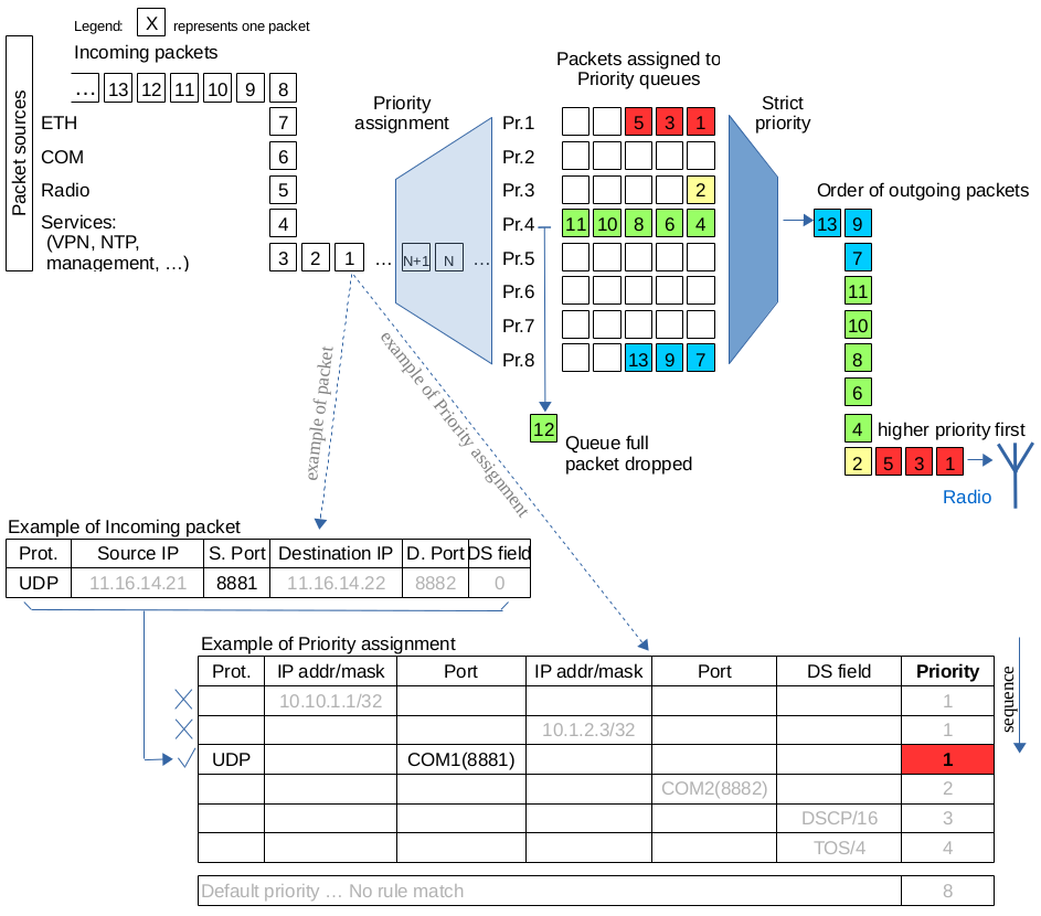
* Active only when Router mode
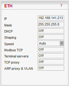
Default = 192.168.169.169
IP address of ETH interfaceDefault = 255.255.255.0
Mask of ETH interfaceDefault = 0.0.0.0 (= not active)
When Operating mode is set to Bridge, it is the default gateway (applies to whole RipEX). When Operating mode is set to Router, it is not displayed here. Default GW can be set only in the Routing menu.List box: Off, Server
Default = OffServer
DHCP (Dynamic Host Configuration Protocol) Server in RipEX sets network configuration (IP address, Mask, Gateway) in connected DHCP clients. They have to be connected to the same LAN as the ETH interface of RipEX. The Mask set is the same as on RipEX ETH, the Gateway is the IP address of ETH interface of RipEX. Typical DHCP client is e.g. a PC used for configuration of RipEX.IMPORTANT:
Never activate the DHCP Server when ETH interface of RipEX is connected to LAN, where another DHCP server is operating.Start IP
Default = IP address of ETH interface + 1
DHCP Server assigns addresses to connected clients starting from this address.End IP
DHCP server assigns IP addresses to clients from the range defined by Start IP and End IP (inclusive).No of leases
Default = 5 [1 – 255]
Maximum number of DHCP client(s) which can RipEX simultaneously serve. It can not be more than the number of addresses available in the Start IP – End IP range.Lease timeout [DD:HH:MM:SS]
Default = 1 day (max. 10 days)
A DHCP Client has to ask DHCP Server for refresh of the received configuration within this timeout, otherwise the Lease expires and the same settings can be assigned to another device (MAC).Assigned IPs
Table shows MAC addresses of Clients and IP addresses assigned to them by the Server. Expiration is the remaining time till the respective Lease expires. If the assigned IP addresses are required to be deleted, set DHCP Server to Off, then action Apply and set DHCP server to On (+Apply) again.Preferred IPs
It is possible to define which IP should be assigned by the Server to a specific MAC. The requested IP has to be within the Start IP – End IP range.
List box: On, Off
Default = Off
Ethernet interface could easily overload the Radio channel. Because of that, it is possible to shape traffic received from the ETH interface.
If “On”, specified volume of Data [Bytes] in specified Period [s] is allowed to enter the RipEX from ETH interface. The first packet which exceeds the limit is stored in the buffer and transmitted when new Period starts. Further over-limit packets are discarded.List box: Auto, 100baseTX/Full, 100baseTX/Half, 10baseT/Full, 10baseT/Half
Default = Auto
Communication speed on the Ethernet interface.Use this settings only for Modbus TCP Master when it communicates with both types of Modbus slaves using either Modbus RTU or Modbus TCP protocols. Or when TCP/IP communication should run locally between Modbus Master and RipEX in Modbus TCP network. Read Help and Application note Modbus in RipEX.
For more information refer to the manual Application note / Modbus TCP.
** – denotes items to be used only when either all or some RTUs (Remote Telemetry Unit) on remote sites are connected via RS232 or RS485 interface to RipEX, using the Modbus RTU protocol. Then automatic conversion between Modbus TCP and Modbus RTU protocols takes place for such units.
List box: On, Off
Default = OffMy TCP port
Default = 502
TCP port used for Modbus TCP in RipEX.TCP Inactivity [s]
Default = 120
TCP socket in RipEX is kept active after the receipt of data for the set number of seconds.Broadcast**
List box: On, Off
Default = Off
Some Master SCADA units send broadcast messages to all Slave units. SCADA application typically uses a specific address for such messages. RipEX (Protocol utility) converts such message to an IP broadcast and broadcasts it to all RipEX units resp. to all SCADA units within the network.
If On, the address for broadcast packets in SCADA protocol has to be defined:Broadcast address format – List box Hex, Dec – format in which broadcast address is defined.
Broadcast address – address in the defined format (Hex, Dec)
Address translation
List box: Table, Mask
Default = Mask
In a SCADA protocol, each SCADA unit has a unique address, a “Protocol address”. In RipEX Radio network, each SCADA unit is represented by an IP address (typically that of ETH interface) and a UDP port (that of the protocol daemon or the COM port server to which the SCADA device is connected via serial interface).A translation between “Protocol address” and the IP address & UDP port pair has to be done. It can be done either via Table or via Mask.
Each SCADA message received from serial interface is encapsulated into a UDP/IP datagram, where destination IP address and destination UDP port are defined according the settings of Address translation.
Mask
Translation using Mask is simpler to set, however it has some limitations:
− all IP addresses used have to be within the same network, which is defined by this Mask
− the same UDP port is used for all the SCADA units, which results in the following limitations:− SCADA devices on all sites have to be connected to the same interface (COM1 or COM2)
− only one SCADA device to one COM port can be connected, even if the RS485 interface is used
Default = IP address of ETH interface
When the IP destination address of the UDP datagram, in which serial SCADA message received from COM1(2) is encapsulated, is created, this Base IP is taken as the basis and only the part defined by Mask is replaced by ‘Protocol address’.Mask
Default = 255.255.255.0
A part of Base IP address defined by this Mask is replaced by ‘Protocol address’. The SCADA protocol address is typically 1 Byte, so Mask 255.255.255.0 is most frequently used.UDP port (Interface)
List box: COM1, COM2, TS1-TS5, MBTCP, Manual.
Default = COM1
This UDP port is used as the destination UDP port in the UDP datagram in which serial SCADA packet received from COM1(2) is encapsulated. Default UDP ports for COM1, COM2 or Terminal servers 1-5 (TS1-TS5) or Modbus TCP (MBTCP) can be used or UDP port can be set manually. If the destination IP address belongs to a RipEX and the UDP port is not assigned to COM1(2) or to a Terminal server or to any special daemon running in the destination RipEX, the packet is discarded.
Table
The Address translation is defined in a table. There are no limitations like when the Mask translation is used. If there are more SCADA units on RS485 interface, their “Protocol addresses” translate to the same IP address and UDP port pair.
There are 3 possibilities how to fill in a line in the table:
1. One “Protocol address” to one “IP address” (e.g.: 56 ===> 192.168.20.20)
2. Interval of “Protocol addresses” to one “IP address” (e.g.: 56 – 62 ===> 192.168.20.20)
3. Interval of “Protocol addresses” to interval of “IP addresses” (e.g.: 56 – 62 ===> 192.168.20.20 – 26). It is possible to write only the start IP and dash, the system will add the end address itself.Protocol address
This is the address which is used by SCADA protocol. It may be set either in Hexadecimal or Decimal format according the List box value.
Protocol address length can be maximum 1 Byte.IP
IP address to which Protocol address will be translated. This IP address is used as destination IP address in UDP datagram in which serial SCADA packet received from COM1(2) is encapsulated.UDP port (Interface)
This is the UDP port number which is used as destination UDP port in UDP datagram in which the serial SCADA message, received from COM1(2), is encapsulated.Note
You may add a note to each address up to 16 characters long (UTF8 is supported) for your convenience. (E.g. “Remote unit #1 etc.). Following characters are not allowed:
” (Double quote)
` (Grave accent)
\ (Backslash)
$ (Dollar symbol)
; (Semicolon)Active
You may tick/untick each translation line in order to make it active/not active.Modify
Delete and Add buttons allow to add or to delete a line. The lines can be sorted using up and down arrows.
Generally a Terminal Server (also referred to as a Serial Server) enables connection of devices with serial interface to a RipEX over the local area network (LAN). It is a virtual substitute for devices used as serial-to-TCP(UDP) converters.
Examples of the use:
A SCADA application in the centre should be connected to the Radio network via a serial interface, however for some reason that serial interface is not used. The operating system (e.g. Windows) can provide a virtual serial interface to such application and converts the serial data to TCP (UDP) datagrams, which are then received by the Terminal server in RipEX. This type of interconnection between RipEX and application is especially advantageous when:there is not any physical serial interface on the computer
the serial cable between the RipEX and computer would be too long (e.g. the RipEX is installed very close to the antenna to improve radio coverage).
the LAN between the computer and the place of RipEX installation already exists
Modbus TCP is used with local TCP sessions on slave sites or when combination of Modbus RTU and Modbus TCP is used. For more information refer to Application note Modbus TCP/RTU This applies also to other SCADA protocol TCP versions, e.g. DNP3 TCP.
NOTE: The TCP (UDP) session operates only locally between the RipEX and the central computer, hence it does not increase the load on Radio channel.
In some special cases, the Terminal server can be also used for reducing the network load from applications using TCP. A TCP session can be terminated locally at the Terminal server in RipEX, user data extracted from TCP messages and processed like it comes from a COM port. When data reaches the destination RipEX, it can be transferred to the RTU either via a serial interface or via TCP (UDP), using the Terminal server again.
List box: On, Off
Default = OffIf “On”, up to 5 independent Terminal servers can be set up. Each one can be either of TCP or UDP Type, Inactivity is the timeout in sec for which the TCP socket in RipEX is kept active after the last data reception or transmission, My IP address of a Terminal server has to be always the same as the IP address of the RipEX ETH interface, My Port can be set as required. Destination IP and Destination port values belong to the locally connected application (e.g. a virtual serial interface). In some cases, applications dynamically change the IP port with each datagram. In such a case set Destination port=0. RipEX will then send replies to the port from which the last response was received. This feature allows to extend the number of simultaneously opened TCP connections between a RipEX and locally connected application to any value up to 10 on each Terminal server. Protocol follows the same principles as a protocol on COM interface. You may tick/untick each individual Terminal server in order to make it active/inactive.
NOTE: Max. user data length in a single datagram processed by the Terminal server is 8192 Bytes.
Compared to UDP, the TCP protocol generates more load (longer headers, extra handshake datagrams), which in some circumstances may significantly reduce the user data throughput in a narrowband radio modem network. The TCP proxy module converts TCP to UDP (and vice-versa) so that only UDP datagrams are transferred over the Radio channel. TCP sessions are maintained only locally between the end RipEX and the connected application device (at both ends of the RipEX network).
NOTE 1: The TCP proxy module is activated and configured independently in each end RipEX. To successfully handle an end-to-end application TCP session, the two respective end RipEX units have to be configured properly to match the same destination and source address/port pairs.
NOTE 2: Some applications use the TCP session status or handshake datagrams (TCP ACK) RTT for important decisions at the application level. It is not recommended to use TCP proxy with such applications, since the status of the local TCP sessions at the respective ends of the RipEX network is not synchronized. It is also highly recommended to use TCP proxy only with the ACK setting „On” (Settings/Device/Operating mode). Nevertheless be aware that any individual datagram can be lost. The locally run TCP sessions cannot guarantee 100% data integrity end-to-end.
NOTE 3: RipEX can handle up to 100 concurrent TCP proxy connections.
List box: On, Off
Default = OffTCP Inactivity [s]
Default = 120
Timeout in sec for which the TCP socket in RipEX is kept active after the last data reception or transmission.IP
IP address or interval of IP addresses (e.g.: 192.168.20.20 – 192.168.20.26) for which the TCP/UDP conversion is done.
0.0.0.0 means all IP addresses.Port
Port or interval of Ports (e.g.: 40100 – 40200), in conjunction with IP addresses in the same line, for which the TCP/UDP conversion is done.Direction
Dst – IP and Port as defined above are considered as Destination in the received packet
Src – IP and Port as defined above are considered as Source in the received packetNote
You may add a note to each address up to 16 characters long (UTF8 is supported) for your convenience. (E.g. “Remote unit #1 etc.). Following characters are not allowed:
” (Double quote)
\ (Backslash)
$ (Dollar symbol)
; (Semicolon)Active
You may tick/untick each line in order to make it active/not active.Modify
Delete and Add buttons allow to add or to delete a line. The lines can be sorted using up and down arrows.
General description
ARP proxy (Router mode only)
When a remote device connected over a Router-mode RipEX network does not support routing (i.e. the default gateway cannot be configured), the narrowest possible subnet should be configured on the respective Eth interface of the RipEX connected to it and the ARP proxy switched on. The RipEX then answers ARP requests for all IP addresses routed to its radio interface. Corresponding settings can be used in the RipEX connected to the central application device, thus enabling the routed RipEX network to act as a direct (V)LAN connection for such devices.
WARNING:
Whenever there is more than one IP device connected to a RipEX, or even more RipEX units connected to the same physical Eth,
the ARP proxy must be used with the utmost care!
Subnets routed to the radio interface must be reduced to the minimum necessary, default gateway should never be used. Accidental unwanted ARP responses may destroy all communication in the connected LAN!VLAN
Unlimited number of VLANs can be set, but only for the ETH interface, not for the Radio one. VLAN is defined by VLAN ID and IP and Mask. Several different Subnets can be assigned to a VLAN. Each VLAN may be seen as a virtual ETH0.VLAN_ID interface. In addition to setting multiple VLANs, the original ETH0 interface may be left non-VLAN, i.e. for receiving/transmitting frames without a VLAN tag.
Router mode
When ARP proxy&VLAN is On, the RipEX Eth interface can receive/transmit also frames with the respective VLAN IDs. Upon receiving a frame, the VLAN tag is stripped and the IP packet continues through the RipEX network according to the routing table rules. When a packet is routed to be transmitted over one of the virtual Eth interfaces, the respective VLAN tag is added to the frame.
NOTE 1: Since the VLAN ID added to a packet/frame transmitted from Eth interface depends solely on the local RipEX configuration (Routing table and VLAN), it is independent of the original VLAN ID which has been stripped off upon the packet entry into the first RipEX. Remember to double-check your configuration to avoid VLAN ID mismatching.
NOTE 2: When in Router mode, no Subnet on Ethernet may overlap with a Subnet on Radio interface. Subnets on Ethernet could overlap each other (they may not be identical). For the sake of clarity, we nevertheless recommend IP subnets for different VLANs to be set without any overlapping.
Bridge mode
VLAN settings apply only to packets destined to the local RipEX (e.g. management traffic, terminal server sessions etc.) All the remaining packets (frames) are processed transparently by the bridge regardless of their VLAN tags (these are kept untouched). Packets forwarded to the radio interface are transmitted as broadcasts over the radio channel. Reciprocally, only the packets sourced in the local RipEX are processed according to VLAN setting, i.e. possibly tagged with the respective VLAN ID. Packets arriving over the radio channel are again transparently forwarded, depending on the bridge MAC address table.
Configuration
List box: On, Off
Default = OffTo create Subnet click on Add Subnet. The new Subnet line appears. Fill in IP/MASK. Unlimited number of virtual Ethernet interfaces (Alias IP addresses) can be set.
To create VLAN click on Add VLAN.The new VLAN line appears. Each VLAN can have its Subnets. Network overlapping among subnets is possible. When overlapping, the subnet with the narrowest mask takes effect for respective IP.
Interface.VLAN ID
Behind decimal point in ETH0. fill in VLAN ID. Values 1 – 4094 are possible.
The first line (Main Ethernet interface) can be also defined as the VLAN. Tick the box and the unit can be “VLAN only”.Priority
List box: possible values
Default = 0 Fixed priority can be assigned to a VLAN frame which is created in outgoing RipEX.NOTE: Priority Code Point (PCP): a 3-bit field which refers to the IEEE 802.1p priority. It indicates the frame priority level. Values are from 0 (best effort) to 7 (highest); 1 represents the lowest priority. These values can be used to prioritize different classes of traffic (voice, video, data, etc.).
Unit Manag.
Tick when RipEX management shall be possible using this VLAN. Make sure Unit Management is On for one VLAN at least (typically the Eth0). Remember you could lose the connection to your RipEX.
ARP proxy
Available only when Operating mode is set to Router.
When ticked, the respective interface generates ARP responses for all IP addresses which are routed to the Radio interface according to the Routing table (in this specific RipEX unit).
Be very careful when using this feature, ARP proxy can disable all traffic in the LAN !
NOTE 1: When two RipEX units are connected via their Ethernet ports in the same LAN, their IP networks defined on Radio interface must not overlap (both units would reply to the same ARP request).
NOTE 2: It is highly recommended to activate ARP proxy as the last change when all the other settings are done.
NOTE 3: Check your routing rules twice – routing within a single LAN requires careful IP address planning to fit as narrow subnet masks as possible for the individual routes.
Note
You may add a note to each line up to 16 characters long (UTF8 is supported) for your convenience. (E.g. “Remote unit #1 etc.). Following characters are not allowed:
” (Double quote)
` (Grave accent)
\ (Backslash)
$ (Dollar symbol)
; (Semicolon)Active
You may tick/untick each line in order to make it active/not active. VLAN is active when at least one of its subnets is active (even the first line can be inactive).
Modify
Add Subnet creates the new Subnet line. Add VLAN creates the new VLAN line. Delete deletes respective line. The VLAN lines can be sorted using up and down arrows.
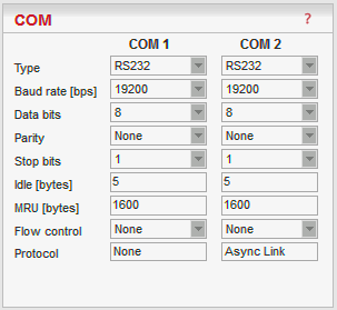
* Active only when Router mode
The COM ports in RipEX are served by special daemons, which are connected to the IP network through a standard Linux socket. Consequently a COM port can be accessed using any of the two IP addresses (either ETH or Radio interface) used in a RipEX and the respective UDP port number. The source IP address of outgoing packets from COM ports is equal to IP address of the interface (either Radio or Ethernet) through which the packet has been sent. Outgoing interface is determined in Routing table according to the destination IP. The default UDP port numbers are COM1 = 8881, COM2 = 8882. If necessary they may be changed using CLI, nevertheless it is recommended to stick to the default values because of dependencies between different settings (e.g. Protocols) in the network.
| Note | |
|---|---|
UDP port settings is valid only in Router mode. In Bridge mode all packets received by COM port are broadcasted to all COM ports on all RipEX units within the network. |
List box: possible values
Default = RS232
COM1 is always RS232, COM2 can be configured to either RS232 or RS485.Note The settings of Data rate, Data bits, Parity and Stop bits of COM port and connected device must match.
List box: standard series of rates from 300 to 115200 bps
Default = 19200
Select Baud rate from the list box: 300 to 115200 bps rates are available.
Serial ports use two-level (binary) signaling, so the data rate in bits per second is equal to the symbol rate in baudsList box: 8, 7
Default = 8
The number of data bits in each character.List box: None, Odd, Even
Default = None
Wikipedia: Parity is a method of detecting errors in transmission. When parity is used with a serial port, an extra data bit is sent with each data character, arranged so that the number of 1-bits in each character, including the parity bit, is always odd or always even. If a byte is received with the wrong number of 1s, then it must have been corrupted. However, an even number of errors can pass the parity check.List box: possible values
Default = 1
Wikipedia:Stop bits sent at the end of every character allow the receiving signal hardware to detect the end of a character and to resynchronise with the character stream.Default = 5 [0 – 2000]
This parameter defines the maximum gap (in bytes) in the received data stream. If the gap exceeds the value set, the link is considered idle, the received frame is closed and forwarded to the network.Default = 1600 [1 – 1600]
MRU (Maximum Reception Unit) — an incoming frame is closed at this size even if the stream of bytes continues. Consequently, a permanent data stream coming to a COM results in a sequence of MRU-sized frames sent over the network.Note Very long frames (>800 bytes) require good signal conditions on the Radio channel and the probability of a collision increases rapidly with the length of the frames. Hence if your application can work with smaller MTU, it is recommended to use values in 200 – 400 bytes range.
This MRU and the MTU in Radio settings are independent. However MTU should be greater or equal to MRU.
List box: None, RTS/CTS
Default = None
RTS/CTS (Request To Send / Clear To Send) hardware flow control (handshake) between the DTE (Data Terminal Equipment) and RipEX (DCE – Data Communications Equipment) can be enabled in order to pause and resume the transmission of data. If RX buffer of RipEX is full, the CTS goes down.
NOTE: RTS/CTS Flow control requires a 5-wire connection to the COM port.List box: None, Async Link, C24, Cactus, Comli, DF1, DNP3, IEC101, ITT Flygt, Modbus, PR2000, Profibus, RDS, RP570, Siemens 3964(R), Slip, UNI
Default = None
Each SCADA protocol used on serial interface is more or less unique. The COM port daemon performs conversion to standard UDP datagrams used in RipEX Radio network. Each protocol has its individual configuration parameters, which are described in separate Help page (accessible from configuration light box Protocol – click on Protocol, then on Help). Protocol “None” simply discards any data received by the COM port or from the network, which means that the respective COM port is virtually disconnected from the RipEX.
This menu provides the following protocols:
|
Each SCADA protocol like Modbus, DNP3, IEC101, DF1 etc. has its unique message format, most importantly its unique way of addressing of remote units. The basic task for protocol utility is to check whether received frame is within protocol format and it is not corrupted. Most of the SCADA protocols are using some type of Error Detection Codes (Checksum, CRC, LRC, BCC, etc.) for data integrity control, so RipEX calculates this code and check it with the received one.
RipEX radio network works in IP environment, so the basic task for Protocol interface utility is to convert SCADA serial packets to UDP datagrams. The Address translation settings are used to define the destination IP address and UDP port. Then these UDP datagrams are sent to RipEX router, processed there and they are typically forwarded as unicasts to Radio channel to their destination. When the gateway defined in the Routing table belongs to the Ethernet LAN, UDP datagrams are rather forwarded to the Ethernet interface. After reaching the gateway (typically a RipEX router again), the datagram is forwarded according to the Routing table.
Note Even if UDP datagrams, they can be acknowledged on the Radio channel (ACK parameter of Router mode), however they are not acknowledged on Ethernet.
When the UDP datagram reaches its final IP destination, it should be in a RipEX router again (either its ETH or Radio interface). It is processed further according its UDP port. It can be delivered to COM1(2) port daemon, where the datagram is decapsulated and the data received on the serial interface of the source unit are forwarded to COM1(2). The UDP port can also be that of a Terminal server or any other special protocol daemon on Ethernet like Modbus TCP etc. The datagram is then processed accordingly to the respective settings.
RipEX uses a unique, sophisticated protocol on Radio channel. This protocol ensures high probability of data delivery. It also guarantees data integrity even under heavy interference or weak signal conditions due to the 32 bit CRC used, minimises the probability of collision and retransmits frame when a collision happens, etc., etc. These features allow for the most efficient SCADA application arrangements to be used, e.g. multi-master polling and/or spontaneous communication from remote units and/or parallel communication between remote units etc.
Note These Radio protocol features are available only in the Router mode. The Bridge mode is suitable for simple Master-Slave arrangement with a polling-type application protocol.
All timeouts in parameters described below are calculated from time, when packet is sent into COM driver, i.e. it includes the transfer time of the packet. Take it into account especially when there is a low Baud rate set in COM settings.
The parameters described in this section are typical for most protocols.
There is only a link to them in description of the respective Protocol.Mode of Connected device
List box: Master, Slave
Default = Master
Typical SCADA application follows Master-Slave scheme, where the structure of the message is different for Master and Slave SCADA units. Because of that it is necessary to set which type of SCADA unit is connected to the RipEX.Note For SCADA Master set Master, for SCADA Slave set Slave.
Master
SCADA Master always sends addressed messages to Slaves. The way of addressing is different from SCADA protocol to SCADA protocol, so this is one of the main reasons why an individual Protocol utility in RipEX for each SCADA protocol has to be used.Broadcast
List box: On, Off
Default = Off
Some Master SCADA units sends broadcast messages to all Slave units. SCADA application typically uses a specific address for such messages. RipEX (Protocol utility) converts such message to a customized IP broadcast and broadcasts it to all RipEX units resp. to all SCADA units within the network.
If On, the address for broadcast packets in SCADA protocol has to be defined:Broadcast address format – List box Hex, Dec – format in which broadcast address is defined.
Broadcast address – address in the defined format (Hex, Dec)
Address translation
List box: Table, Mask
Default = Mask
In a SCADA protocol, each SCADA unit has a unique address, a “Protocol address”. In RipEX Radio network, each SCADA unit is represented by an IP address (typically that of ETH interface) and a UDP port (that of the protocol daemon or the COM port server to which the SCADA device is connected via serial interface).
A translation between “Protocol address” and the IP address & UDP port pair has to be done. It can be done either via Table or via Mask.
So SCADA message received from serial interface is encapsulated into a UDP/IP datagram, where destination IP address and destination UDP port are defined according the settings of Address translation.Mask
Translation using Mask is simpler to set, however it has some limitations:
− all IP addresses used have to be within the same network, which is defined by this Mask
− the same UDP port is used for all the SCADA units, which results in the following limitations:Base IP
Default = IP address of ETH interface
When the IP destination address of UDP datagram, in which serial SCADA message received from COM1(2) is encapsulated, is created, this Base IP is taken as the basis and only the part defined by Mask is replaced by ‘Protocol address’.Mask
Default = 255.255.255.0
A part of Base IP address defined by this Mask is replaced by ‘Protocol address’. The SCADA protocol address is typically 1 Byte, so Mask 255.255.255.0 is most frequently used.UDP port (Interface)
List box: COM1,COM2, TS1-TS5, MBTCP, Manual.
This UDP port is used as the destination UDP port in UDP datagram in which serial SCADA packet received from COM1(2) is encapsulated. Default UDP ports for COM1, COM2 or Terminal servers 1-5 (TS1-TS5) or Modbus TCP (MBTCP) can be used or UDP port can be set manually. If the destination IP address belongs to a RipEX and the UDP port is not assigned to COM1(2) or to a Terminal server or to any special daemon running in the destination RipEX, the packet is discarded.
Table
The Address translation is defined in a table. There are no limitations such as when the Mask translation is used. If there are more SCADA units on RS485 interface, their “Protocol addresses” should be translated to the same IP address and UDP port pair, where the multiple SCADA units are connected. There are 3 possibilities how to fill in the line in the table:
− One “Protocol address” to one “IP address” (e.g.: 56 ===> 192.168.20.20)
− Interval of “Protocol addresses” to one “IP address” (e.g.: 56 – 62 ===> 192.168.20.20)
− Interval of “Protocol addresses” to interval of “IP addresses” (e.g.: 56 – 62 ===> 192.168.20.20 – 26). It is possible to write only the start IP and dash, the system will add the end address itself.Protocol address
This is the address which is used by SCADA protocol. It may be set either in Hexadecimal or Decimal format according the List box value.
Protocol address length can be 1 Byte, only for some protocols, e.g. DNP3 and UNI can also be 2 Bytes.IP
IP address to which Protocol address will be translated. This IP address is used as destination IP address in UDP datagram in which serial SCADA packet received from COM1(2) is encapsulated.UDP port (Interface)
This is UDP port number which is used as destination UDP port in UDP datagram in which the serial SCADA message, received from COM1(2), is encapsulated.Note
You may add a note to each address with your comments up to 16 characters (UTF8 is supported) for your convenience. (E.g. ” Remote unit #1 ” etc.). Following characters are not allowed:
” (Double quote)
` (Grave accent)
\ (Backslash)
$ (Dollar symbol)
; (Semicolon)Active
You may tick/un-tick each translation line in order to make it active/not active.Modify
Edit Delete Add buttons allow to edit or to add or to delete a line. The lines can be sorted using up and down arrows.
SCADA Slave typically only responds to Master requests, however in some SCADA protocols it can communicate spontaneously.
Messages from serial interface are processed in similar way as at Master site, i.e. they are encapsulated in UDP datagrams, processed by router inside the RipEX and forwarded to the respective interface, typically to Radio channel.
All received frames from COM port as well as from the RipEX network are discarded.
Async link creates asynchronous link between two COM ports on different RipEX units. Received frames from COM1(2) or from a Terminal server 1-5 are sent without any processing transparently to Radio channel to set IP destination and UDP port. Received frames from Radio channel are sent to COM1 or COM2 or Terminal server 1-5 according UDP port settings.
Parameters
Destination IP
This is IP address of destination RipEX, either ETH or Radio interface.UDP port (Interface)
This is UDP port number which is used as destination UDP port in UDP datagram in which packet received from COM1(2) is encapsulated.
C24 is a serial polling-type communication protocol used in Master-Slave applications.
When a RipEX radio network runs in the Router mode, multiple C24 Masters can be used within one Radio network and one Slave can be polled by more than one Master.
Italicised parameters are described in Common parameters.
Protocol frames
List box: 1C, 2C, 3C, 4C
Default = 1C
One of the possible C24 Protocol frames can be selected.Frames format
List box: Format1,Format2,Format3,Format4,Format5
Default = Format1
One of the possible C24 Frames formats can be selected. According to the C24 protocol specification, it is possible to set Frames formats 1-4 for Protocol frames 1C-3C and formats 1-5 for 4C.Important The RipEX accepts only the set Protocol frames and Frames format combination. All other combinations frames are discarded by the RipEX and not passed to the application.
Local ACK
List box: Off, On
Default = Off
Available for Protocol frame 1C only. When “On”, ACK on COM1(2) is send locally from this unit, not over the Radio channel.
Cactus is a serial polling-type communication protocol used in Master-Slave applications.
When a RipEX radio network runs in the Router mode, multiple Cactus Masters can be used within one Radio network and one Slave can be polled by more than one Master.Italicised parameters are described in Common parameters.
Broadcast
There is not the possibility to set Broadcast address, since Cactus broadcast messages always have the address 0x00. Hence when the Broadcast is On, packets with this destination are handled as broadcasts.
Max gap timeout [ms]
Default = 30
The longest time gap for which a frame can be interrupted and still received successfully as one frame. It should not be set below 10ms, while 15–40 ms should be OK for a typical Cactus protocol device.
Comli is a serial polling-type communication protocol used by Master-Slave application.
When RipEX radio network run in Router mode, more Comli Masters can be used within one Radio network and one Slave can be polled by more Masters.
Broadcasts packets are not used, so the configuration is using only some parameters described Common parameters.Only the full duplex mode of DF1 is supported. Each frame in the Allen-Bradley DF1 protocol contains the source and destination addresses in its header, so there is no difference between Master and Slave in the Full duplex mode in terms of RipEX configuration.
Block control mode
List box: BCC, CRC
Default = BCC
According to the DF1 specification, either BCC or CRC for Block control mode (data integrity) can be used.Broadcast
According to the DF1 specification, packets for the destination address 0xFF are considered broadcasts. Hence when Broadcast is On, packets with this destination are handled as broadcasts.Advanced parameters
ACK Locally
List box: Off, On
Default = On
If “On”, ACK frames (0x1006) are not transferred over-the-air.
When the RipEX receives a data frame from the connected device, it generates the ACK frame (0x1006) locally. When the RipEX receives the data frame from the Radio channel, it sends the frame to the connected device and waits for the ACK. If the ACK is not received within 1 sec. timeout, RipEX sends ENQ (0x1005). ENQ and ACK are not generated for broadcast packets.
Each frame in the DNP3 protocol contains the source and destination addresses in its header, so there is no difference between Master and Slave in terms of the RipEX configuration. The DNP3 allows both Master-Slave polling as well as spontaneous communication from remote units.
Broadcast
There is not the option to set the Broadcast address, since DNP3 broadcast messages always have addresses in the range 0xFFFD – 0xFFFF. Hence when Broadcast is On, packets with these destinations are handled as broadcasts.
IEC 870-5-101 is a serial polling-type communication protocol used by Master-Slave application.
When RipEX radio network run in Router mode, more IEC 870-5-101 Masters can be used within one Radio network and one Slave can be polled by more Masters.
IEC 870-5-101 protocol configuration is using all parameters described in Common parameters.Broadcast
On, Off only. Protocol broadcast address is not configurable, it is defined by Address mode in Advance parameter (default 0xFF)
Advanced parameters
Address mode
Even if IEC 870-5-101 is the standard, there are some users which customized this standard according their needs. When addressed byte has been moved, RipEX has to read it on the correct location.IEC101
Address byte location according to IEC 870-5-101 standard.
Broadcast from Master station is generated when address byte is 0xFF.2B ADDR
Two byte address (IEC 870-5-101 standard is 1 Byte). The frame is 1 Byte longer than standard one. There is Intel sequence of bytes: low byte, high byte. Mask Address translation has to be used, because Table one is limited just to one byte address length.
Broadcast from Master station is generated when address is 0xFFFF.TELEGYR
The Control byte in standard IEC packet is omitted. The frame is 1 Byte shorter than standard one. This is typically used in Telegyr 805/809 protocol.
Broadcast from Master station is generated when address byte is 0x00.SINAUT
The sequence of Address byte and Control byte in the frame is changed-over.
Broadcast from Master station is generated when address byte is 0x00.
ITT Flygt is a serial polling-type communication protocol used in Master-Slave applications.
ITT Flygt protocol configuration uses all parameters described in Common parameters.
Broadcast
There is not a possibility to set the Broadcast address, since ITT Flygt broadcast messages always have the address 0xFFFF. Hence when the Broadcast is On, packets with this destination are handled as broadcasts.First Slave Address
Default = 1
Slave addresses are not defined in the ITT Flygt protocol. However Slave addresses have to be defined in the RipEX network. This is the First Slave address in decimal format.Number of Slaves
Default = 1
Since the ITT Flygt protocol Master (centre) polls the Slaves (remotes) one by one without any addressing, number of slaves has to be defined.
Wait timeout [ms]
Default = 5000
An ITT Flygt Slave sometimes sends the WAIT COMMAND (0x13) to its Master. The RipEX does not accept the next WAIT COMMAND (discards it), till the Wait timeout does not expire. The Recommended value is in the 1-10 seconds range.
Modbus RTU is a serial polling-type communication protocol used by Master-Slave application.
When RipEX radio network run in Router mode, more Modbus Masters can be used within one Radio network and one Slave can be polled by more Masters.
Modbus protocol configuration uses all parameters described in Common parameters.Advanced parameters, Slave
Retries [No]
Default = 0 (min. 0, max. 7)
When an original frame is received from the Radio channel, it is transmitted to the connected device and waits for an acknowledgement. Any incoming frame from the device is treated as an acknowledgement. If there is no acknowledgement (no incoming frame), the original frame is re-transmitted to the connected device. The Retries parameter controls how many times the frame is re-transmitted when not acknowledged.Repeat timeout [ms]
Default = 300 (min. 0, max. 8190)
The Repeat timeout parameter controls how long the unit waits for an acknowledgement frame (see Retries parameter description). The timeout is started when the original frame received from the Radio channel is transmitted to the connected device (over the serial channel). Transmission of any other frame to the connected device is temporarily blocked, whilst Repeat timeout is active. Repeat timeout = 0 disables this feature.
PR2000 is an abbreviation for the PROTEUS 2000 SCADA protocol. This protocol is used in Master-Slave applications.
The PR2000 protocol is implemented in a fully transparent manner. The original protocol frames are transported over the RipEX network in their entirety.
The PR2000 protocol configuration uses the following parameters as described in Common parameters:RipEX supports Profibus DP (Process Field Bus, Decentralized Periphery) the widest-spread version of Profibus. The Profibus protocol configuration uses all parameters described in Common parameters.
RDS protocol is a protocol used in MRxx networks. It supports network communication; any node in the network can talk to any other (unlike Master-Slave type of protocols). The RDS protocol should only be used when combining RipEX and MRxx networks or SCADA networks adapted to MRxx networks.
Frames are received from the Radio channel and sent to COM1, COM2 or Terminal server 1-5 according to UDP port settings and vice versa – from wire to radio channel.
Italicised parameters are described in Common parameters.
ACK
List box: On, Off
Default = On
Frame acknowledgement when transmitted over wire (COM or Ethernet) interface. ACK (0x06) frames are transmitted on successful reception and NAK (0x15) on unsuccessful frame reception.ACK timeout [ms]
Default = 1000 (min. 0, max. 65535)
When “ACK” is enabled, RipEX is waiting “ACK timeout [ms]” after transmitting frame to receive acknowledgement. If the ACK frame isn’t received, the frame is re-transmitted. Frame re-transmission happens up to “Repeats” number of times.Repeats
Default = 2 (min. 0, max. 65535)
Number of frame re-transmissions.Reverse mode
List box: On, Off
Default = On
If a frame must be transmitted over a further wire channel, source and destination addresses in the frame must be reversed.Reverse address (Hex)
Default = 00 (min. 0x00, max. 0xFF)
When Reverse mode is enabled, the destination address is overwritten by Reverse address when the frame is received from the wire channel and before it is transmitted to the air channel. This only happens if the Reverse mode is enabled.
RP570 is a serial polling-type communication protocol used in Master-Slave applications.
When a RipEX radio network runs in the Router mode, multiple RP570 Masters can be used within one Radio network and one Slave can be polled by more than one Master.
Italicised parameters are described in Common parameters.
Local simulation RB
List box: Off, On
Default = Off
The RP570 protocol Master very often transmits the RB packets (hold packets) solely to check whether slaves are connected. In order to minimize the Radio channel load, the RipEX can be configured to respond to these packets locally and not to transmit them to the slaves over the Radio channel.If “On”, the RipEX responds to RB packets received from the RP 570 master locally over the COM interface. However from time to time (RB period) the RB packets are transferred over the network in order to check whether the respective slave is still on. When the RB response from the slave to this RB packet is not received over the Radio channel within the set RB timeout, i.e. the respective slave is out of order, the central RipEX stops local answering to RB packets from the master for the respective slave.
RB Net period [s]
Default = 10
The RipEX responds to the RB packets locally and in the set RB period the RB packets are transferred over the network.RB Net timeout [s]
Default = 10 (maximum=8190)
Whenever an RB packet is sent over the network, the set RB Net timeout starts. When the RB response from the remote unit (slave) is not received within the timeout, i.e. the respective slave is out of order, the central RipEX stops the local answering to RB packets from the master for the respective slave.
Local simulation RB
List box: Off, On
Default = Off
The RP570 Slave expects to receive RB packets from the Master. When the Local simulation RB on the Master is On, the RB packets are transferred over the Radio channel only in the RB Net period (see Master settings). The Local simulation RB has to be set the same (On or Off) on all sites in the network, i.e. on the master as well as all slaves.If On, the RipEX generates RB packets locally and transmits them over the COM interface in the RB Request period and expects the RB response for each RB packet from the RP570 Slave within the RB Response timeout. When the RipEX does not receive the response(s) from the RP570 slave, the RipEX does not respond to the RB packet from the Master which it receives over the Radio channel.
RB Request period [ms]
Default = 200 (maximum=8190)
RipEX sends locally RB packets to the connected RTU in the set period.RB Response timeout [ms]
Default = 500 (maximum=8190)
The RipEX expects a response to the RB packet within the set timeout. If it is not received, the RipEX does not respond to RB packets from the Master received over the Radio channel.RTU address (Hex)
Default = 01
Active only when the Local simulation RB is On. The connected RTU’s address is supposed to be filled in. This address (0x00-0xFF) is used in the RB packets generated locally in the RipEX and transmitted over the COM.
The 3964 protocol is utilized by the Siemens Company as a Point-to-Point connection between two controllers. Meanwhile it has developed into an industry standard that can be found on many devices as a universal communications interface. 3964R is the same as 3964, in addition it only uses BCC (Block Check Character). 3964(R) handles only the link layer (L2 in OSI model), hence RipEX uses a similar way to read “SCADA address” as in UNI protocol.
There is a handshake STX(0x02) – DLE(Ox10) on the start of communication and DLE+ETX – DLE on the end. This handshake is performed by RipEX locally, it is not transferred over the RipEX network.
Communication goes as follows:
LocalRTU -> STX -> LocalRipEX
LocalRipEX -> DLE -> LocalRTU
LocalRTU -> DATA+DLE+ETX+BCC -> LocalRipEX
LocalRipEX -> DATA -> RemoteRipEX*
LocalRipEX -> DLE -> LocalRTU
RemoteRipEX -> STX -> RemoteRTU
RemoteRTU -> DLE -> RemoteRipEX
RemoteRipEX -> DATA+DLE+ETX+BCC -> RemoteRTU
RemoteRTU -> DLE -> RemoteRipEX* only this packet is transferred over the RipEX network, all the other ones are handled locally.
Italicised parameters are described in Common parameters.
Address mode
List box: Binary (1 B), Binary (2B LSB first). Binary (2B MSB first).
Default = Binary (1 B)
RipEX reads the Protocol address in the format and length set (in Bytes).Address position
Specify the sequence number of the byte, where the Protocol address starts.
NOTE 1: 3964(R) protocol is using escape sequence (control sequence) for DLE(0x10). I.e. when 0x10 is in user data, 0x1010 is sent instead. When address position is calculated, the bytes added by escape sequence algorithm are not taken into account.
NOTE 2: The first byte in the packet has the sequence number 1, not 0.
DLE timeout [ms]
Default = 1000 (min. 300, max. 8190)
RipEX expects a response (DLE) from the connected device (RTU) within the set timeout. If it is not received, RipEX repeats the frame according to the “Retries” setting.Retries [No]
Default = 3 (min. 0, max. 7)
When DLE timeout is „On”, and DLE packet is not received from the connected device (RTU) within the set DLE timeout, RipEX retransmits the frame. The number of possible retries is specified.Priority
List box: Low, High
Default = Low
When the equipment sends STX and receives STX instead of DLE, there is a collision, both equipments want to start communication. In such a case, one unit has to have a priority. If the Priority is High, RipEX waits for DLE. When it is Low, RipEX send DLE.
NOTE: Obviously, two pieces of equipment which are communicating together must be set so that one has High priority and the other has Low.BCC
List box: On, Off
Default = On
BCC (Block Check Character) is a control byte used for data integrity control, it makes the reliability higher. BCC is used by 3964R, 3964 does not use it.
RipEX checks (calculates itself) this byte while receiving a packet on COM. RipEX transmits DLE (accepts the frame) only when the check result is OK. BCC byte is not transferred over the RipEX network, it is calculated locally in the end RipEX and appended to the received data.
SLIP (Serial Line Internet Protocol) allows the Internet Protocol (IP), normally used on Ethernet, to be used over a serial line. SLIP modifies a standard IP packet by prepending and appending a special SLIP END character to it, which allows packets to be distinguished as separate. SLIP requires a COM port configuration of 8 data bits, no parity and flow control. SLIP does not provide error detection, being reliant on other high-layer protocols for this. A SLIP connection needs to have its IP address configuration set each time before it is established.
Local IP
IP address assigned to COM port (local point of SLIP protocol) used for p-t-p communication with Connected device. It has to be within the subnet defined by Peer IP and Peer IP mask.Peer IP
This is IP address of Connected device (remote point of SLIP protocol) on the other end of RS232.Peer IP mask
Peer IP and Peer IP mask defines Subnet, which is routed into SLIP on respective COM.
NOTE: Peer IP and Peer IP mask defines IP subnet which is automatically routed to respective COM. This subnet can not overlap with any other subnet in RipEX defined on Radio, ETH or VLAN.
UNI is the ‘Universal’ protocol utility designed by RipEX. It is supposed to be used when the application protocol is not in the RipEX list and the addressed mode of communication is preferable in the network (which is a typical scenario). The key condition is that messages generated by the Master application device always contain the respective Slave address and that address (or its relevant part) position, relative to the beginning of the message (packet, frame), is always the same (Address position).
Generally two communication modes are typical for UNI protocol: In the first one, communication has to be always initiated by the Master and only one response to a request is supported; in the second mode, Master-Master communication or combination of UNI protocol with ASYNC LINK protocol and spontaneous packets generation on remote sites are possible.
The UNI protocol is fully transparent, i.e. all messages are transported and delivered in full, without any modifications. Italicised parameters are described in Common parameters.
Address mode
List box: Binary (1 B), ASCII (2 B), Binary (2B LSB first). Binary (2B MSB first).
Default = Binary (1 B)
RipEX reads the Protocol address in the format and length set (in Bytes).The ASCII 2-Byte format is read as 2-character hexadecimal representation of one-byte value. E.g. ASCII characters AB are read as 0xAB hex (10101011 binary, 171 decimal) value.
Address position
Specify the sequence number of the byte, where the Protocol address starts. Note that the first byte in the packet has the sequence number 1, not 0.Address mask (Hex)
When the Address mode is Binary 2 Bytes, a 16-bit value is read from the SCADA protocol message according to the Address mode setting (either the MSB or the LSB first), The resulting value is then bit-masked by the Address mask and used as the input value for SCADA to IP address translation (e.g. by a table). The default value of the Address mask is FFFF, hence the full 16-bit value is used by default.Example:
The Address mode is set to Binary (2B LSB first), the Address mask is set to 7FF0 and the Address position is set to 2. The SCADA message starts with bytes (in hex) 02 DA 92 C3 .. The 2-Byte address is read as 0x92DA (note the LSB came first in the message), Then 0x7FF0 mask is applied and the resulting value 0x12D0 (0x92DA & 0x7FF0) is used as the input for the translation.Poll response control
List box: On, Off
Default = On“On” – The Master accepts only one response per a request and it must come from the specific remote to which the request has been sent. All other packets are discarded. This applies to the Master – Slave communication scheme.
NOTE: It may happen, that a response from a slave (No.1) is delivered after the respective timeout expired and the Master generates the request for the next slave (No.2) in the meantime. In such case the delayed response from No.1 would have been considered as the response from No.2. When Poll response control is On, the delayed response from the slave No.1 is discarded and the Master stays ready for the response from No.2.
“Off” – The Master does not check packets incoming from the RF channel – all packets are passed to the application, including broadcasts . That allows E.g. spontaneous packets to be generated at remote sites. This mode is suitable for Master-Master communication scheme or a combination of the UNI and ASYNC LINK protocols.
Advanced parameters
CTS Envelope
List box: On, Off
Default = Off
On – CTS Envelope function makes it possible to use the CTS signal to control radio transmission in some old transparent radio networks. This feature is used to enable smooth migration from a legacy to the new RipEX based networks. See Migration solution.
The “Flow control” parameter must be disabled to enable the “CTS Envelope” to function.CTS Pre-time [ms]
The CTS signal (CTS Pre-time) is activated a number of milliseconds prior to transmitting the data from the serial port.CTS Post-time [ms]
The CTS signal (CTS Post-time) is deactivated a number of milliseconds after the data has been transmitted from the serial port.COM Broadcast delay [ms]
Radio transmissions in the transparent network are delayed by this parameter to make it possible to transmit the broadcast in the RipEX network first.
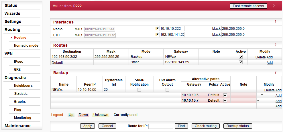
Routing table is active only when Router mode
(Settings/Device/Operating mode) is set. In such a case RipEX works as a standard IP router
with 2 independent interfaces: Radio and ETH. Each interface has its own MAC address, IP
address and Mask. IP packets are then processed according the Routing
table.
Unlimited number of Subnets and VLAN’s can be defined on the ETH
interface, menu Settings/Device/ARP proxy & VLAN. They are routed independently.
The COM ports are treated in the standard way as router devices, messages can be
delivered to them as UDP datagrams to selected UDP port numbers. Destination IP address of
COM port is either IP of ETH or IP of Radio interfaces. The source IP address of outgoing
packets from COM ports is equal to IP address of interface (either Radio or Ethernet)
through packet has been sent. Outgoing interface is determined in Routing table according
the destination IP.
The IP addressing scheme can be chosen arbitrarily, only
127.0.0.0/8 and 192.0.2.233/30 and 192.0.2.228/30 restriction applies. It may happen that
also the subsequent addresses from the 192.0.2.0/24 subnet according RFC5737 may be reserved
for internal usage in the future.
Radio
IP address and Mask define the IP network (Radio LAN) within RipEX can communicate directly over the Radio channel, however the radio repeater (defined as the gateway in the route) can be used. All units which are supposed to communicate directly have to be within the same Radio LAN.ETH
IP address and Mask define the IP network (LAN) in which RipEX can communicate directly over the Ethernet. All devices which should be accessible directly have to be within the same LAN.
If Subnets (Aliases) or VLAN’s are defined (menu Settings/Device/ARP proxy & VLAN) you can see them by clicking on VLAN & Subnets on the right side.
Destination, Mask, Gateway
Each IP packet, received by RipEX through any interface (Radio, ETH, COM1 or COM2), has got a destination IP address. RipEX (router) forwards the received packet either directly to the destination IP address or to the respective Gateway, according to the Routing table. Any Gateway has to be within the network defined by IP and Mask of one of the interfaces (Radio, ETH), otherwise the packet is discarded.
Each line in the routing table defines a Gateway (the route, the next hop) for the network (group of addresses) defined by Destination IP and Mask. When the Gateway for the respective destination IP address is not found in the Routing table, the packet is forwarded to the Default gateway. When Default gateway is not defined (0.0.0.0), the packet is discarded.
The network (Destination and Mask) can by specified in both formats. Either 10.11.12.13/24 in Destination or 10.11.12.13 in Destination and 255.255.255.0 in Mask columns. RipEX displays and converts both formats. There is also a balloon tip while the cursor is in the specific line on the Mask. It shows which IP addresses are included in the network which is routed to the respective Gateway.NOTE: Networks defined by IP and Mask for Radio and ETH interfaces must not overlap.
Mode
List box: Static, Backup, Nomadic
Default = StaticStatic
Used for static IP routing rules. If the next hop on the specific route is over the radio channel, the Radio IP is used as a Gateway. If Base driven protocol is used and the destination Remote is behind a Repeater, the destination Remote Radio IP is used as a Gateway (not the Repeater address).Backup
Any Backup route defined in Backup table can be assigned to a specific route. Assignment is achieved by selecting “Backup” Mode and putting the Backup route Name to the Gateway. The same Backup can be assigned for different routes.Nomadic
If the station is configured using Flexible protocol and Nomadic mode with the station type “Remote”, any routing rule forwarding traffic to the Center must be set to “Nomadic”.
Note
You may add a note to each route with your comments up to 16 characters (UTF8 is supported) for your convenience. (E.g. “Central station” etc.). Following characters are not allowed:
” (Double quote)
` (Grave accent)
\ (Backslash)
$ (Dollar symbol)
; (Semicolon)Active
You may tick/un-tick each route in order to make it active/not active. This feature is advantageous e.g. when one needs to redirect some route temporarily. When Default GW is un-ticked to not active, its Gateway is set to 0.0.0.0 and Backup is set to Off. The other lines keep their settings even when not-active.Modify
Delete and Add buttons allow to delete or add a line. One may order the lines using up and down arrows.
RipEX is capable to test path between two RipEX IP addresses (even behind a repeater or LAN). When the connection fails, RipEX automatically uses alternative gateway(s) defined in the Alternative paths column with the priority according to the line sequence. The system always tries to use the route with the highest priority, e.g. automatically switches back when the failed route starts to work.
Hello packets are used for path testing. Each direction (back and forth) is tested independently, i.e. the routing can be non-symmetrical. Data in the transmitted Hello packet carry the information about received Hello packets from the counterpart (Peer IP). The path is evaluated as the good one, when Hello packets from counterpart (carried the info, that counterpart successfully received ‘my’ Hello packets) are received. i.e. each side decides itself which outbound route (gateway) will be used.
Backup path status is displayed: Up – green background, Down – red background, Unknown – yellow background, Currently used – bold.
Name
You can name Backup path as per your choice. The name can be up to 16 characters long (UTF8 is supported) for your convenience. (E.g. “Remote unit #1 etc.). Following characters are not allowed:” (Double quote)
` (Grave accent)
\ (Backslash)
$ (Dollar symbol)
; (Semicolon)Peer IP
IP address of the RipEX (either its Radio or Ethernet interface) on the remote end of the Backup path (Hello packet is sent there). Only RipEX IP of Radio or the main Ethernet interface can be used, no Subnets.
NOTE: Do not forget to set correct routing to „Peer IP” for Hello packets.Hysteresis [s]
Alternative path is kept for the time set in order to avoid chaotic switching among different paths under unstable conditions.SNMP Trap
When ticked, SNMP Trap is sent whenever there is a change in the path status: Up, Down, Unknown, Currently used.HW Alarm Output
NOTE: HW Alarm Output has to be enabled first, i.e. Settings/Alarm management/HW Alarm Output must not be „Off”
When ticked , the HW Alarm Output contact on the Power connector is activated when the highest priority Gateway of the respective Backup path fails. When the HW Alarm Output is ticked for multiple Backups, it is activate while at least one of the highest priority Gateways is in the fail stateGateway
More Gateways (alternatives) can be defined for one Backup path. When the path using the first (highest priority) Gateway fails, the next one (defined on the next line) is automatically used. Gateway displayed in Bold is currently used.Policy
Policy defines the conditions for switching to the alternative gateway.Parameters
List box: Default, Manual,
Default = DefaultDefault – Default (recommended) values are set and can not be edited.
Manual – Values can be set manually.
Hello packet period [s]
Default = 60 sec, [Max=3600]
When the set period expires, the next Hello packet is transmitted. To avoid the collisions, there is a jitter of approx. 5%.Hello packet success rate [%]
List box: possible values
Default = 87.5
When success rate of Hello packets drops bellow this threshold, the unit switches to the next alternative gateway in the line. Hello packet success rate evaluation is based on last 8 transmitted Hello packets. (The info about successfully delivered outbound Hello packets are carried by received Hello packets).RSS [-dBm]
Default = Off [255= Off]
Hello packets carry the info about average RSS (saved in respective Statistic table) on each radio hop on its way. When any RSS on the way is lower than the set one, the unit switches to the next alternative gateway in the line. Each individual packet is evaluated.Test when lower priority
NOTE: This menu item has been renamed to improve understanding. It read “Lower priority path checking” until FW ver. 1.4.x.x. Its functionality has NOT been changed.
List box: On/Off
Default = On
If On, the alternative path is tested, even if it is lower priority than the currently active one (Hello packets are transmitted). Advantage – if the active path fails, system switches only to a functional alternative. Disadvantage – when e.g. GSM for backup is used, Hello packets used for testing are charged. When Off, the respective alternative path is tested only when its priority is higher than that of the active path.
NOTE 1: The number of Backup paths is not limited. The number of Alternative routes is min.2 and max. 16 (active ones). There can be more than 16 Alternative routes defined, only the active ones are tested.
NOTE 2: When Optimization (Settings/Radio/Optimization) is “On”, UDP packets with both source and destination port 8886 are not transferred over the network, they are discarded in the end RipEX. UDP packets with source port 8903 are not optimized, even if Optimization is “On”.
NOTE 3: When SW key Backup routes or Master key expires, Backup path configuration is lost.
– applies and saves the changes.
– restores original values.
– finds (highlights the respective line in the table) the route for a specific IP address if exists.
– highlights duplicate routes for specific IP if they exist.
– refresh the status of backup routes (Good, Failure, Unknown, Currently used)
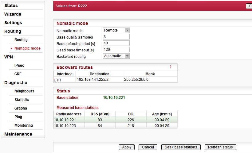
Nomadic mode is a method of building a network that offers easy addition of a new ‘nomadic remote’ station to the radio network or easy transfer of ‘nomadic remote’ stations between different ‘nomadic base’ stations. Switching between ‘nomadic base’ stations will not be a rapid process; in order of minutes and longer.
Nomadic mode is only available in Router mode operating in Flexible radio protocol.
There are 3 types of network stations in a Nomadic mode enabled network:
Center: There can only be one Center in a Nomadic network. This is the root of any Nomadic network topology. Any Nomadic tunnel forwarding user traffic to Remotes is originated here. The Center can also act as a Base
Base: The station to which Remotes connect
Remote: Connected over one radio hop to the Base and through the Base to the Center. Nomadic tunnel encapsulates traffic between Remote and Center
All figures below represent simplified examples of a Nomadic network using the following abbreviations:
C – Center
B – Base
R – Remote
FEP – Front End Processor – application center for user data
RTU – Remote Terminal Unit – application end point

The Remote station broadcasts a “seek” packet – Base stations within radio coverage reply
Connection is automatically established through the Base station with strongest signal
Routing rules to and from Remote to Center are established automatically
The maximum number of Remotes that can be connected to one Base is 64
If there is no connection between Base and Center, Remotes connected to the Base automatically initiate new Base station search

Remote is connected to the Base with best signal quality. User traffic from the RTU is transferred through the Nomadic tunnel from the Remote to the Center and transmitted to the FEP and vice versa.

Checks are carried out at pre-set intervals to establish which Base station provides strongest signal
Signal must be more than 5 dBm stronger to force a Base station change

The Base is checked periodically to see if it is still connected to the Center. If there is no connection, the Remote connects to another Base with the strongest signal.
Nomadic mode
List box: Off, Remote, Base, Center
Default = Off
Nomadic mode selection.Center – Configuration
Base stations
All Base stations within the network are listed in this table
The number of Active Bases is limited to 256
The same IP address can not be used more than once
The “Unknown Base stations” records can be accessed to add a new Base to the table
IP address
Default = 0.0.0.0
Base station IP address. The primary ETH address or the Radio IP address must be used. The IP address type used (Radio or ETH) must match the IP address assigned in Base configuration settings.Active
Use check box to activate/deactivate the ruleNote
You may add a note to each rule up to 16 characters in length (UTF8 is supported). Characters not allowed:
” (Double quote)
` (Grave accent)
\ (Backslash)
$ (Dollar symbol)
; (Semicolon)Modify
Delete and Add buttons allow the user to delete or add a record (navigate the records using up and down arrows).Base – Configuration
IP address of the Center
Default = 0.0.0.0
Radio or ETH address can be used. The same type of address must be used when configuring the connection to this Base from the Center in the “Base stations” table.Base – Advanced Configuration
Center refresh period [s]
Default = 300 s [1 – 86400]
Refresh period of connection with the Center.
Remote – Configuration
Backward routing
List box: Manual, Automatic
Default: Automatic
Method to establish how Backward routing table is created.Automatic: The primary ETH address range is entered. If the SLIP protocol on COM1 and/or COM2 interface is enabled, the range of address of its tunnel interface is also entered.
Manual: The rules are manually entered in the “Backward routes” configuration table.
Backward routes
Routing rules for routing all the traffic from the Center to the Remote via the Nomadic tunnel.
Rules are transferred to Center after Remote registration. Number of rules is limited to 8. The same IP address range can not be used more than once within the whole network (to prevent routing mismatch).Destination
Default = 0.0.0.0/0
Destination IP address. Matching packets will be forwarded to the Remote.
Note: Both, ETH and Radio address can be used to access COM1 and COM2 by Serial SCADA protocols (Modbus, DNP3 etc.). Default ETH address can be used.Mask
Default = 0.0.0.0
Destination IP address mask.Active
Use check box to activate/deactivate the ruleNote
You may add a note to each rule up to 16 characters in length (UTF8 is supported). Characters not allowed:You may tick/un-tick each rule in order to make it active/not active
” (Double quote)
` (Grave accent)
\ (Backslash)
$ (Dollar symbol)
; (Semicolon)Forward rules
Configured in Routing – Routes table.
Rules to route the traffic from the Remote to the Center.
The “Mode” parameter of each routing rule (Routing – Routes) must be set to “Nomadic” in order to establish forwarding to the Nomadic tunnel.
The “Default GW” must also be configured. If the RTU unit is directly connected to the Ethernet port, this rule is enough; no other routing rule is necessary.Remote – Advanced Configuration
Base quality samples
Default = 3 [3 – 8]
Number of packets used to asses signal quality between Remote and Base. Higher number equals longer process but more accurate signal quality measurement. User data transmission may be affected by this process.Base refresh period [s]
Default = 3600 s [10 – 86400]
The period of refreshing Remote station registration in its Base.Dead Base timeout [s]
Default = 120 s [5 – 120]
Used to set time period to check Base station availability. Service packet checking the Base availability is sent after this timeout if there is no other communication running. No response initiates a new Base search.
Remote stations are accessible using Fast remote access using the same address as is configured in their Backward routing tables. The nomadic protocol uses UDP datagrams, with default port number 8905.
Center – Status
Base stations
Configured Base stations list provides the following status information:Base stations connected to Center are highlighted in green
Base stations not connected to Center are highlighted in red
Unknown Base stations
Provides a list of Base stations configured as nomadic Base but not added to “Base stations” list in the Center. Use the “Add” button to complete configuration setup.Remotes
All Remotes connected to the network are listed with the following details provided:Remote Radio and ETH address
Remote Serial number
Base station address the Remote is connected to. If connected directly to the Center “Center” is listed instead of IP address
Time since the last registration
Remote station record is highlighted in red if evidence suggests Remote station IP address is duplicated
List of Backward routes
Backward route record is not highlighted if the rule is accepted
Backward route record is highlighted in light green if there is a collision and the rule is accepted
Backward route record is highlighted in red if there is a collision and the rule is not accepted
Locally connected Remotes
Remotes connected directly to the Center are listed with the following details provided:Remote Radio address
Remote Serial number
Time since the last record refresh
Measured Remotes (local)
This table provides the following results of signal quality measurement between Remote stations and the Center. Signal is measured when Remote is checking for Base station with best signal.Remote Radio address
RSS and DQ measurement
Time since the last measurement
Remotes connected to the Center are highlighted in green
Base – Status
Connection to the Center status indicates if the Base is connected to the Center.
Connected Remotes
Remotes connected to the Base are listed with the following details provided:Remote Radio address
Remote Serial number
Time since the last record refresh
Measured Remotes
This table provides the following results of signal quality measurement between Remote stations and the Base. Signal is measured when Remote is checking for Base station with best signal.Remote Radio address
RSS and DQ measurement
Time since the last measurement
Connected Remotes are highlighted in green
Remote – Status
Base station – IP address for the Base station the Remote is connected to.
Measured Base stations
This table provides the following results of signal quality measurement between Remote stations and the Base stations within radio coverage. Signal is measured when Remote is checking for Base station with best signal.Remote Radio address
RSS and DQ measurement
Time since the last measurement
Active Base is highlighted in green
Base stations having rejected a connection are highlighted in red
Advanced – Monitoring
There is no dedicated monitoring for the Nomadic mode
The Nomadic protocol mode packets can be monitored on the “RADIO” interface as UDP frames with default port 8905
The Nomadic tunnel can be monitored on the “ETH” interface at the Center or Remote terminal. The “User rule” must be set as “-i nomad”
Packets originating in a unit routed to the Nomadic tunnel use the primary ETH address as their Source address
Communication between different Remote stations is possible but must be routed via the Center
Communication between a Remote station and a static network station is also possible but must be routed via the Center
Firewall
Firewall can not be used to filter packets between Center and Remotes forwarded through the tunnel
For the packet filtering rules based on interface (“Input device”, “Output device”). If the “Radio” option is used, the Nomadic tunnel may be affected.
Optimization
Optimization can only be used for User and management traffic between Remote and Center
Traffic from Remote to another unit via the Center can not be Optimized
Proxy ARP
Proxy ARP is working correctly for the address behind the nomadic connection
Terminal servers
Terminal servers can communicate over the Nomadic tunnel
TCP Proxy
TCP Proxy can be established over the Nomadic tunnel
IPsec
An IPsec tunnel can be established over the Nomadic tunnel (e.g. between Remote station and Center)
A nomadic connection between Center and Base can be established over the IPsec tunnel
GRE
The GRE tunnel can be established over the Nomadic tunnel
The nomadic connection between Center and Base can be established over the GRE tunnel
Backup routes
It is possible to create a Backup route with one of the alternative paths using a Nomadic tunnel. The “Gateway” address must be set to “127.1.1.1”. The back up routing rules in the Center must be added to the Backward routes in the Remote. Such a scenario can be used to back up a nomadic connection using the radio channel between Center and Remote station using a Cellular network.
Center to Base connection can be back up using Backup routes
HotStandby
Remote, Base and Center can be operated in HotStandby configuration
If the unit is hot-swapped, it can be reported in the Center as being duplicated. The message disappears after a certain time.
VPN (Virtual Private Network) extends a private network across a public network, and enables users to send and receive data across shared or public networks as if their computing devices were directly connected to the private network. Applications running across the VPN may therefore benefit from the functionality, security, and management of the private network.
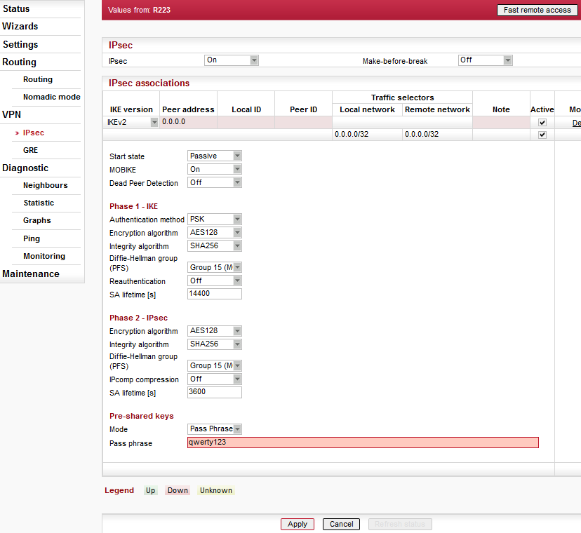
Internet Protocol Security (IPsec) is a network protocol suite that authenticates and encrypts the packets of data sent over a network. IPsec includes protocols for establishing mutual authentication between agents at the beginning of the session and negotiation of cryptographic keys for use during the session. IPsec uses cryptographic security services to protect communications over Internet Protocol (IP) networks. IPsec supports network-level peer authentication, data-origin authentication, data integrity, data confidentiality (encryption), and replay protection. IPsec is an end-to-end security scheme operating within the Internet Layer of the Internet Protocol Suite. IPsec is recognized as a secure, standardized and well-proven solution by the professional public.
Although there are 2 modes of operation RipEX only offers Tunnel mode. In Tunnel mode, the entire IP packet is encrypted and authenticated. It is then encapsulated into a new IP packet (ESP – Encapsulating Security Payloads) with a new IP header.
Symmetrical cryptography is used to encrypt the packets. The symmetric keys must be safely delivered to the peer. In order to maintain a secure connection, symmetric keys must be regularly exchanged. The protocol used for secure key exchange is IKE (Internet Key Exchange). Both IKE version 1 and the newer version 2 are available in RipEX.
IKE protocol communication with the peer is established using UDP frames on port 500. However, if NAT-T (NAT Traversal) or MOBIKE (MOBile IKE) are active, the UDP port 4500 is used instead.
NOTE:
NAT-T is automatically recognized by IPsec implementation in RipEX.
The IPsec tunnel is provided by Security Association (SA). There are 2 types of SA:
IKE SA: IKE Security Association providing SA keys exchange with the peer.
CHILD SA: IPsec Security Association providing packet encryption.
Every IPsec tunnel contains 1 IKE SA and at least 1 CHILD SA.
Link partner (peer) secure authentication is assured using Pre-Shared Key (PSK) authentication method: Both link partners share the same key (password).
As and when the CHILD SA expires, new keys are generated and exchanged using IKE SA.
As and when the IKE SA version IKEv1 expires – new authentication and key exchange occurs and a new IKE SA is created. Any CHILD SA belonging to this IKE SA is re-created as well.
As and when the IKE SA version IKEv2 expires one of two different scenarios might occur:
If the re-authentication is required – the behavior is similar to IKEv1 (see above).
It the re-authentication is not required – only new IKE SA keys are generated and exchanged.
IPsec
IPsec
List box: On, Off
Default = Off
IPsec system turning On/OffMake-before-break
List box: On, Off
Default = Off
This parameter is valid for all IKE SA using IKEv2 with re-authentication. A temporary connection break during IKE_SA re-authentication is suppressed by this parameter. This function may not operate correctly with some IPsec implementations (on peer side).
IPsec associations
Every line in the table represents one IKE SA. There can be a maximum of 8 active IKE SA (limited by system resources).
The “Peer ID” is a unique identifier of the IKE SA serving as a link between CHILD SA (“Traffic selectors” table) and PSK.
IKE version
List box: IKEv1, IKEv2
Default = IKEv2
IKE version selection. The IKE peer must use the same version.Peer address
Default = 0.0.0.0
IKE peer IP address.Local ID
IP address or FQDN (Fully Qualified Domain Name) is used as the Local side identification. It must be same as “Peer ID” of the IKE peer.Peer ID
IP address or FQDN (Fully Qualified Domain Name) is used as the IKE peer identification. It must be same as “Local ID” of the IKE peer. The “Peer ID” must be unique in the whole table.Note
You may add a note to each tunnel with your comments up to 16 characters (UTF8 is supported) for your convenience. Following characters are not allowed:
” (Double quote)
` (Grave accent)
\ (Backslash)
$ (Dollar symbol)
; (Semicolon)Active
Default = On
When disabled the related IKE SA and all associated CHILD SA are disabled.Traffic selectors
“Traffic selector” defines which traffic is forwarded to the IPsec tunnel. The rule that defines this selection matches an incoming packet to “Local network” and “Remote network” address ranges.Basic rules:
Each line contains the configuration settings of one CHILD SA and indicates its association to a specific IKE SA
There can be a maximum of 16 active CHILD SA (in total over all Active IKE SA)
Every “Active” line must have an equivalent on the peer side with reversed “Local network” and “Remote network” fields
“Local network” and “Remote network” fields must contain different address ranges and must not interfere with the USB service connection (10.9.8.7/28) or internal connection to FPGA (192.0.2.233/30)
Each “Active” Traffic selector in the configuration table must be unique
Configuration:
Local network
Source IP address and mask of the packets to be captured and forwarded to the encrypted tunnel.Remote network
Destination IP address and mask of the packets to be captured and forwarded to the encrypted tunnel.Note
You may add a note to each tunnel with your comments up to 16 characters (UTF8 is supported) for your convenience. Following characters are not allowed:
” (Double quote)
` (Grave accent)
\ (Backslash)
$ (Dollar symbol)
; (Semicolon)Active
List box: On, Off
Default = On
Relevant CHILD SA can be enabled/disabled.
Start state
List box: Passive, On Demand, Start
Default = Passive
This parameter defines initial state of the IPsec connection.Passive: Connection is not established. Waiting for the peer to initiate the connection
On Demand: Connection is established when first packet transmission through tunnel is attempted; packet is waiting for the connection to be established
Start: Connection is established immediately
MOBIKE
List box: On, Off
Default = On
Enables MOBIKE for IKEv2 supporting mobility or migration of the tunnels. Please note IKE is moved from port 500 to port 4500 when MOBIKE is enabled. The peer configuration must match.Dead Peer Detection
List box: On, Off
Default = On
Detection of lost connection with the peer. IKE test packets are sent periodically. When packets are not acknowledged after several attempts, the connection is closed (corresponding actions are initialized). In the case when Detection is not enabled, a connection loss is discovered when regular key exchange process is initiated.DPD check period [s]
Default = 30 sec. Range [5 – 28800] sec
Dead Peer Detection check period.Dead Peer Detection
List box: Clear, Hold, Restart
Default = Hold
One of three connection states automatically activated when connection loss is detected:Clear: Connection is closed and waiting
Hold: Connection is closed. Connection is established when first packet transmission through tunnel is attempted
Restart: Connection is established immediately
Phase 1 – IKE
Parameters related to IKE SA (IKE Security Association) provide SA keys exchange with the peer.Authentication method
List box: PSK
Default = PSK
Peer authentication method. Peer configuration must match.
The “main mode” negotiation is the only option supported. The “aggressive mode” is not supported; it is recognized as unsafe when combined with PSK type of authenticationEncryption algorithm
List box: 3DES (legacy), AES128, AES192, AES256
Default = AES128
IKE SA encryption algorithm. The “legacy” marked methods are recognized as unsafe. Peer configuration must match.Integrity algorithm
List box: MD5 (legacy), SHA1 (legacy), SHA256, SHA384, SHA512
Default = SHA256
IKE SA integrity algorithm. The “legacy” marked methods are recognized as unsafe. Peer configuration must match.
The same value as selected for the Integrity algorithm, is used for the PRF (Pseudo-Random Function).Diffie-Hellman group (PFS)
List box: None (legacy), Group 2 (MODP1024, legacy), Group 5 (MODP1536, legacy), Group 14 (MODP2048), Group 15 (MODP3072), Group 25 (ECP192), Group 26 (ECP224), Group 19 (ECP256), Group 20 (ECP384), Group 21 (ECP521), Group 27 (ECP224BP), Group 28 (ECP256BP), Group 29 (ECP384BP), Group 30 (ECP512BP)
Default = Group 15 (MODP3072)
The PFS (Perfect Forward Secrecy) feature is performed using the Diffie-Hellman group method.
PFS increases IKE SA key exchange security. The RipEX unit load is seriously affected when key exchange is in process. The “legacy” marked methods are recognized as unsafe. Peer configuration must match.
The higher the Diffie-Hellman group, the higher the security but also the higher the network and CPU load.Reauthentication
List box: On, Off
Default = Off
This parameter is valid if IKEv2 is used. It determines the next action after IKE SA has expired. When enabled: the new IKE SA is negotiated including new peer authentication. When disabled: only the new keys are exchanged.Phase 2 – IPsec
Certain parameters are shared by all subordinate CHILD SA. IPsec Security Association provides packet encryption (user traffic encryption).Encryption algorithm
List box: 3DES (legacy), AES128, AES192, AES256
Default = AES128
CHILD SA (user traffic) encryption algorithm. The “legacy” marked methods are recognized as unsafe. Peer configuration must matchIntegrity algorithm
List box: MD5 (legacy), SHA1 (legacy), SHA256, SHA384, SHA512
Default = SHA256
CHILD SA (user traffic) integrity algorithm. The “legacy” marked methods are recognized as unsafe. Peer configuration must match.
The same value as selected for the Integrity algorithm, is used for the PRF (Pseudo-Random Function).Diffie-Hellman group (PFS)
List box: None (legacy), Group 2 (MODP1024, legacy), Group 5 (MODP1536, legacy), Group 14 (MODP2048), Group 15 (MODP3072), Group 25 (ECP192), Group 26 (ECP224), Group 19 (ECP256), Group 20 (ECP384), Group 21 (ECP521), Group 27 (ECP224BP), Group 28 (ECP256BP), Group 29 (ECP384BP), Group 30 (ECP512BP)
Default = Group 15 (MODP3072)
The PFS (Perfect Forward Secrecy) feature is performed using the Diffie-Hellman group method.
PFS increases CHILD SA (user traffic) key exchange security. The RipEX unit load is seriously affected when key exchange is in process. The “legacy” marked methods are recognized as unsafe. Peer configuration must match.
The higher the Diffie-Hellman group, the higher the security but also the higher the network and CPU load.IPcomp compression
List box: On, Off
Default = Off
This parameter enables packet compression. This takes place before encryption. Peer configuration must matchSA lifetime [s]
Default = 3600 sec (1 hour). Range [180 – 86400] sec
Time of CHILD SA validity. The new key exchange or re-authentication is triggered immediately the key expires. The true time of expiration is randomly selected within the range of 90-110%, to prevent collision when the key exchange is triggered from both sides simultaneously.
The SA lifetime for CHILD SA is normally much shorter than SA lifetime for IKE SA because the CHILD SA normally transfers much more data than IKE SA (key exchange only). Changing the keys serves as protection against breaking the cypher by analyzing big amounts of data encrypted by the same cypher.
Unfortunately, the more frequent the key exchange, the higher the network and CPU load.Pre-shared keys
PSK (Pre-shared key) authentication is used for IKE SA authentication. The relevant peer is identified using it’s “Peer ID”. The key must be the same for both local and peer side of the IPsec tunnel.Mode
List box: Pass phrase, Key
Default = Pass phrase
How the PSK key is entered.Pass phrase
The PSK key is entered as a password. Empty password is not allowed.Key
The 256 bits long PSK key is entered as a hexadecimal number containing 64 digits.Generate
The Generate button creates a new 256 bits long PSK key and enters it in the Key field.
The IKE SA status is indicated by the color assigned to the configuration row in the IPsec associations table after the “Refresh status” button is selected:
Green color; “Up” status; The IKE SA is established. The associated CHILD SA are also established under normal conditions.
Red color; “Down” status; The IKE SA is not established.
Yellow color; “Unknown” status; The IKE SA status is not available.
Gray color; The individual CHILD SA line:
is not marked as Active, or
it’s configuration was not accepted
Monitoring
IPsec uses UDP frames with port 500 or 4500. IP protocol number 50 is ESP (Encapsulating Security Payloads).
When using monitoring filters, the “Protocol type” filter “UDP and “Other” can be used.
Example of ESP packet monitoring:
14:26:21.899413 [RF:phy:Rx] IP 10.10.1.67 > 10.10.1.41: IP protocol 50, length 174, rss:53 dq:223
RLhead:  4880 ffab 8f5a 5a40 ((MC:B0) 10.10.1.67 > 10.10.1.41 DATA_RTS: T:255 LN:90 Rp:- nA:y Ofr:0)
DChead:  04 (|F:-|C:-|E:a|)
Troubleshooting
User data packets are dropped until the IPsec connection is established. ICMP “admin prohibited” packets are sent back to the source address. The ping response is “Packet filtered”.
There is only one instance of the SA under normal conditions. When the key exchange is in process, two instances may exist at the same moment. The connection can be duplicated in certain circumstances. It should not cause any problems for user traffic. On the other hand, it consumes system resources and increases network load.
When the “SA lifetime” expires and the connection is broken, the “Diffie-Hellman group” is probably set up incorrectly.
IPsec cannot be used in Bridge mode.
Any user defined firewall filtering is active prior to IPsec encryption and after IPsec decryption.
IPsec can be routed via the radio channel. The radio IP address or ETH IP address can be used as a “Peer address”.
IPsec can operate concurrently with IP Optimization. The traffic can be forwarded (based on it’s routing rules) to the IPsec or the optimization module.
IPsec can be routed via the Backup routes. This happens when the “Peer address” is routed using a routing rule with the backup route defined.
IPsec can be used to cooperate with the TCP Proxy. In this case, the packet is captured by TCP Proxy first, encapsulated to UDP frame and then forwarded to the IPsec. The peer side process works in reverse.
IPsec can be used together with the SLIP protocol (COM interface, terminal server). The IPsec tunnel can be configured through the SLIP tunnel and user traffic can be routed to this tunnel.
IPsec can build a connection via VLAN or subnet. A corresponding source address must be selected.
IPsec also functions in Hot Standby mode. When in passive mode, IPsec is turned off. IPsec is started on transition to active mode. New SA (security associations) are opened. On the peer side: the new SA replaces the SA belonging to the RipEX which has transitioned to passive mode.
The specific behavior depends on the “Start state” and “Dead-peer detection” parameters. The fastest transition occurs if the “Start state” parameter is set to “Start” value.
– applies and saves the changes.
– restores original
values.
– refresh the status –
see above
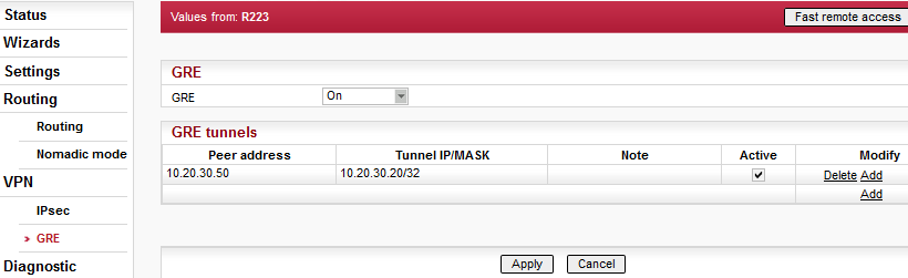
GRE (Generic Routing Encapsulation) is a tunneling protocol developed by Cisco Systems that can encapsulate a wide variety of network layer protocols inside virtual point-to-point links over an Internet Protocol network.
From the point of view of the transferred traffic, the GRE tunnel is one hop
There are 2 modes of GRE operation: TUN (Tunnel mode) or TAP (L2 transparent connection) with SW bridge. RipEX implementation covers only the TUN mode
Packets passing the GRE tunnel are not protected against loss and are not encrypted.
GRE tunnel neither establishes nor maintains a connection with the peer. The GRE tunnel is created regardless of peer status (peer need not exist at all).
GRE tunnel has it’s own IP address and mask. Network defined by this address and mask contains only 2 nodes – each end of the tunnel.
As the GRE tunnel adds an additional header, a lower MTU is set (1476 B) to prevent GRE packet fragmentation. Incoming packets may be fragmented on the GRE interface.
GRE
GRE
List box: On, Off
Default = Off
GRE system turning On/Off
GRE tunnels
Every line in the “GRE tunnels” table defines one GRE tunnel. It is recommended that maximum 20 GRE tunnels are defined. The “Peer address” is a unique GRE tunnel identifier.
Peer address
Defined as the IP address for the opposite end of the GRE tunnel. It is not possible to create multiple GRE tunnels with the same peer address. Corresponding “Peer address” on either side of the GRE tunnel must match.
Routing to this IP address must be configured.Tunnel IP/MASK
Both sides of the tunnel must be configured with the same MASK and different Tunnel IP addresses. The Tunnel IP is used as a “Gateway” when routing traffic to the tunnel.
Routing of assigned packets to the GRE tunnel is provided by the “Routing” configuration. The “Gateway” field shall be filled with the corresponding “Tunnel IP” address (i.e. peer side – “Tunnel IP”)Note
You may add a note to each tunnel with your comments up to 16 characters (UTF8 is supported) for your convenience. Following characters are not allowed:
” (Double quote)
` (Grave accent)
\ (Backslash)
$ (Dollar symbol)
; (Semicolon)Active
You may tick/un-tick each GRE tunnel in order to make it active/not active.
GRE tunnels are named after the pattern “gretunX” where “X” is the tunnel index. Tunnel index is correspond to lines in the “GRE tunnels” starting with “0”. Each line is counted including the lines which are not “Active”. Example: the first line tunnel name is “gretun0”.
Monitoring
IP protocol number 47 is GRE.
To be able to monitor the traffic on the GRE tunnel interface, the GRE tunnel ID must be set up in the ETH monitoring: Advanced parameters/User rule/-i gretun0 (as an example of the first GRE tunnel).
Example of GRE packet monitoring on the Radio interface:
11:18:44.323793 [RF:phy:Tx] IP 10.10.1.41 > 10.10.1.67: IP protocol 47, length 126
Example of GRE packet monitoring on the ETH interface:
11:22:58.643627 [ETH] IP 192.168.1.41 > 192.168.1.1: GREv0, length 88: IP 10.144.1.41 > 10.144.1.2: ICMP echo request, id 319, seq 1, length 64
Troubleshooting
The packet forwarded to the GRE tunnel must only be routed to the corresponding IP at the other side of the tunnel. If the IP address fits the IP address range of the tunnel, but it does not exist, the packet is permanently looped back and forth until the TTL expires. The ICMP message “Time exceeded: TTL expired in transit” is sent to the original sender of the packet.
The tunnel only accepts and extracts GRE packets with a source address which is the same as the GRE tunnel’s Peer address. If a GRE packet from another source appears, it is discarded and the ICMP message “Destination unreachable: Destination port unreachable” is sent to the original sender of the packet.
GRE tunnel cannot be used to access management of the destination unit.
GRE tunnel can be used to manage destination unit using Fast remote access.
User defined firewall can be used to filter packets entering and leaving the GRE tunnel.
Proxy ARP for the LAN interface also works properly for addresses being routed to the GRE tunnel.
GRE tunnel can be routed via the radio channel.
Backup routes can use an alternative path through the GRE tunnel. The “Gateway” in “Alternative path” section must be filled with corresponding “Tunnel IP” address.
GRE tunnel can be routed via the Backup route.
NOTE: GRE packets source address will typically be the main ETH address of the RipEX unit. Configuration settings for the other side of the GRE tunnel must take this into consideration. The RipEX Radio IP will only be selected as a source if the backup route contains a routing rule for the address range of the Radio network (in the “Routes” table).GRE can operate concurrently with IP Optimization. Packets entering the GRE tunnel are not optimized. GRE packets passing through the RipEX are optimized.
Creating a GRE tunnel on top of another GRE tunnel is possible (even in the same RipEX). NOTE: Be careful not to create a network loop! Another GRE tunnel also generates more overhead (another GRE header; packet fragmentation).
GRE can be used together with the TCP Proxy. TCP Proxy is capable of capturing packets leaving the GRE tunnel as well as sending it’s UDP packets over the GRE tunnel.
GRE also functions in Hot Standby mode. The GRE tunnel is state-less so there are no limits in Hot Standby operation.
IPsec traffic can go through the GRE tunnel.
GRE tunnel traffic can be protected using IPsec.
NOTE: The IPsec Traffic selector must be configured to capture the GRE packets without interfering with the routing to the GRE tunnel. When necessary, it is possible to add other addresses in “ARP proxy & VLAN” configuration.
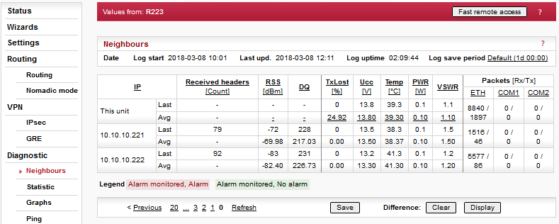
Neighbours and Statistics follow the same pattern.
Most importantly, they
share a common time frame. One Log save period and one Difference log (pair of Clear and
Display buttons) apply to both logs.
For both logs there is a history of 20 log
files available, so the total history of saved values is 20 days (assuming the default value
of 1440 min. is used as Log save period). The files are organized in a ring buffer. Whenever
a new file is opened or the Operating mode is changed, the numbers of files are shifted,
i.e. 0->1, 1->2, etc.
Then both the Neighbours and the Statistic log
values are accumulated and weight-averaged over the whole Log save period (one day by
default). Hence a fresh change in a traffic pattern is not completely averaged out when the
recent log is e.g. 23 hours long.
When a fresh and shorter sample of the log
values is needed, there is a Difference log available. It uses an independent buffer for
data and can be cleared and displayed anytime.
All buttons are common for both logs, Neighbours and Statistic:
button – the log is manually saved, stored in the history file and cleared. This equals to situation when the Log save period expires. When the Operating mode (Bridge / Router) is changed, the log is also Saved.
NOTE: Remember that both the Neighbours and Statistic logs are saved.Difference
button – when pressed, the Difference log is cleared. The standard Neighbour and Statistic logs are not touched. Similarly, when the Log save period expires and the Neighbour and Statistic logs are cleared, the values in Difference log are not touched.
NOTE: Remember that both Neighbours and Statistic logs are cleared.button – displays values of the Difference log, i.e. the values accumulated from time when the Set button has been pressed.
Notice, that the Log start, Last upd. and Log uptime labels at the top change to Diff. start, Diff. upd. and Diff. uptime when the Difference log is displayed. They show the respective values for Difference log.
History
There is a possibility to display history logs using standard buttons. They are placed on the left side of the button bar. The Refresh button displays the latest log values.
Date Information about the actual date and time in the RipEX. It can be set in Settings/Device/Time menu.
Log start
Date and time when the log has been cleared and started.
The log is cleared and started when Log save period expires or when Save button is pressed or when power is switched On.Last update
Date and time when log has been displayed. For actual values click the Refresh button.Log uptime
The difference between Log start and Last update.Log Save period
It redirects to Settings/Device/Neighbours&Statistics where Statistic&Neighbours log save period can be set.
Also the Watched values broadcasting period can be set there. This is a period in which RipEX periodically broadcasts its Watched values to neighbouring units, where they are saved and can be displayed in the Neighbours table.
Neighbours log provides information about neighbouring units (Neighbour = RipEX, which
can be accessed directly over the radio channel, i.e. without a
repeater).
Protocol on Radio channel uses Protocol addresses: MAC address for
Bridge mode and Router – Flexible mode. Protocol address for Router – Base driven mode. A
unit can learn the IP address of its neighbour only when it receives its broadcast of
Watched values (it contains both MAC and IP addresses). Thus when Watched values
broadcasting is Off in a Neighbour (Settings/Device/Neighbours&Statistics), there is
MAC address on the respective line in the Neighbours table. When a known IP address of a
Neighbour changes, the unit cumulates data to the old IP address till it receives the next
Watched values broadcast.
Maximum number of Neighbours listed in the table is
100. If this number is exceeded, the least significant Neighbour is omitted. The first
criterion is whether this RipEX communicates with the Neighbour and the second criterion
is the RSS level.
Neighbours Table
Generally:
there are balloon tips with on line help for column names
the table can be sorted (descending/ascending) by any column, by clicking the column name
two values are displayed for each item: Last and Average. Last is the last value received, the Average is a running average over all values received since the start of the log. The values received more recently weigh up to 50% more in the average than the earlier ones.
if a value in the table is underlined, it is a link to Graphs
green background indicates, that the item is monitored for alarm and its average value is within the “normal” range (Settings/Device/Alarm management)
red background indicates, that the item is monitored for alarm and its average value is in the alarm range (Settings/Device/Alarm management)
when the value of RSS, DQ, Ucc, Temp, PWR, VSWR is not known, N/A is displayed. These N/A values are not displayed in Graphs
Ucc, Temp, PWR, VSWR are refreshed every 1s. The other values in both, Neighbours and Statistics tables are refreshed every 20s
IP addresses:
Bridge mode
Due to broadcast pattern of traffic in Radio channel, all frames generated by user application(s) cumulate in one line in the Neighbour table. When diagnostic or service frames (e.g. Watched values) are transmitted in the network, they are listed in separate lines, distinguished by IP address of their respective Ethernet interfaces.Router mode
MAC addresses of Radio interface are used for link layer communication on Radio channel. When RipEX knows the IP address corresponding with the MAC address (the IP has been the destination IP of a packet transferred), IP address is displayed. If the IP address is not known, the MAC address is displayed.
The first three columns are logged by the receiving RipEX itself.
Received headers [Count]
Total number of frame headers received from the respective RipEX.RSS [dBm]
Received Signal Strength.DQ
Data Quality of received frames. The DQ value is about proportional to BER (bit error ratio) and about independent of the data rate and modulation used. Consequently when data rate is lowered, the DQ value increases and the other way round. Judging the DQ values requires experience, rule-of-thumb figures are as follows. Values: DQ below 100 means the link is unusable, around 125 short packets should start getting through, about 160 and above can be considered “good” values.
The remaining columns contain values broadcasted by neighbouring units in their Watched values broadcasting periods(Settings/Device/Neighbours&Statistics).
TxLost [%]
The probability of a transmitted frame being lost (100 * Lost frames / All transmitted frames).
This value is broadcasted only when Router mode is used and ACK is On.Ucc [V]
Power voltage measured on power input.Temp [°C]
Temperature inside of the RipEX.PWR [W]
The actual value of Radio output power measured by RipEX itself.VSWR
Voltage Standing Wave Ratio (1.0=best, 1.0–1.8=acceptable, >2.5=indicates a serious problem in antenna or feeder)Packets [Rx/Tx]
The total number of packets received from / transmitted to ETH, COM1, COM2 interfaces.
Can be used for interface activity diagnostic.
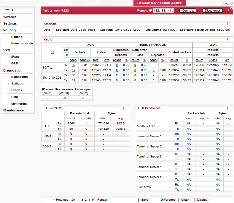
Statistic log provides information about communication on all interfaces: Radio, ETH,
COM1, COM2 and ETH Protocols (Modbus TCP, Terminal servers, TCP proxy). VLAN packets are
part of ETH.
Balloon tips provide on line help for all column names. These
tips explain the meanings and the way of calculation of individual
values.
Meaning of IP addresses listed:
Rx – for received (Rx) packets, the IP source address from UDP header is
displayed. Values in DATA part of the table are calculated for this source IP (origin),
values in RADIO PROTOCOL part are for the last radio hop.
Tx – for transmitted (Tx) packets, the IP destination address
from UDP header is displayed. Values in DATA part of the table are calculated for this
destination IP (final destination), values in RADIO PROTOCOL part are for the next radio
hop.
| Note | |
|---|---|
|
Graphs functions as well as meanings of Overview, Detail, Sampling period are described in the help Settings/Device.
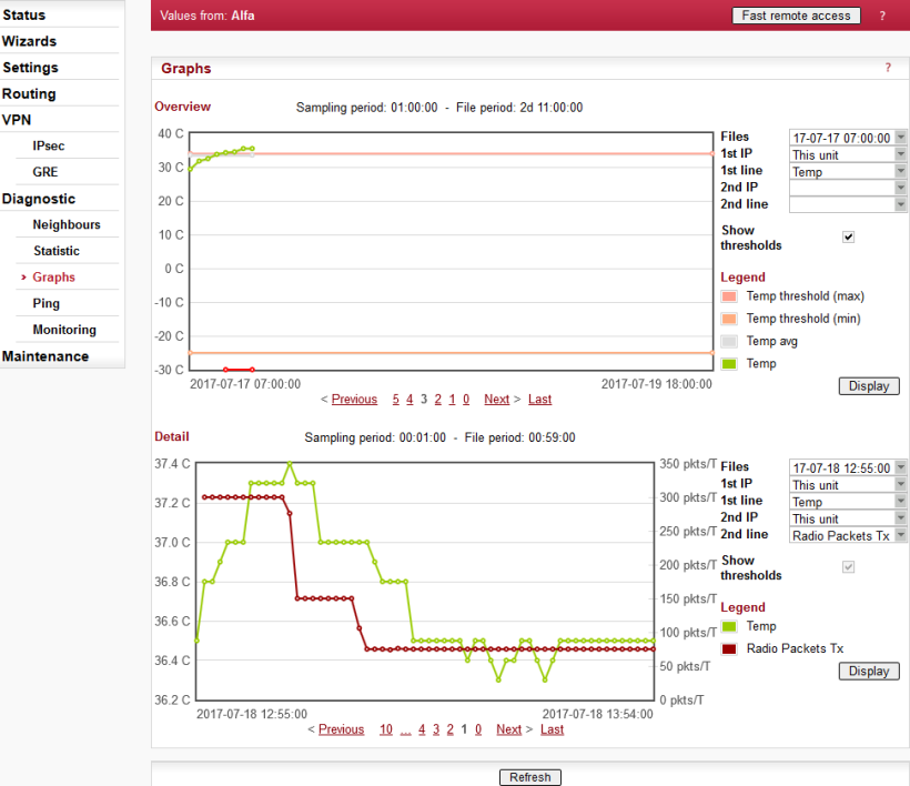
Sampling period
Here just for information, to be set in Settings/Graphs.File period
File period corresponds to the time, for which the values have been recorded in the file. The 60 samples per graph file result in (depending on the Sampling period) 60 (2d 11:00:00), 120 (4d 23:00:00), 240 (9d 23:00:00) or 720 (29d 23:00:00) hours recorded in each file.Available files
List box: possible values
Default = the newest file
There is a list of files, which are saved in RipEX and which can be displayed. Date and time corresponds with the start of the file.1st IP
List box: possible values
Default = This unit
List of IP addresses of RipEX units from which the graph values are available. The list of recorded units can be set in Settings/Device/Graphs. More in help Settings/Device.1st line
List box: possible values
Default = TxLost
There is a list of values, which can be displayed. These values are also recorded in Neighbours or Statistic files. Their meanings can be found in help Neighbours&Statistic.2nd IP, 2nd line
It is possible to display two values from the same unit or from two different ones.Show thresholds
You can show thresholds for the displayed value which are set in the unit (Settings/Device/Alarm management).
When graph file is opened and threshold values are changed, new values are displayed in the next graph file. Present graph works till the end of its range threshold values set when started.Alarm
When displayed value is out of threshold, a red line on the bottom of the graph is shown with its date and time displayed in a balloon tip.History
There is a possibility to change displayed file(s) using standard buttons (Previous 10…6 5 4 .. Next). They are placed below the graph.Buttons
– complete refresh of the screen, i.e. also files in list boxes are updated
– displays/refresh ONLY data in graph according to current settings above
– only for Detail graph. Active (displayed on the screen) when Detail Graph start (to be set in Settings/Graphs) is set to Single. Start button activates the sampling. Stop button can close the file before 60 samples are saved.

Ping (Packet InterNet Groper) is a utility used to test the reachability of a particular
host on an IP network. It operates by sending echo request packets to the target host and
waiting for an echo response. In the process it measures the rtt (round trip time – the time
from transmission to reception) and records any packet loss.
The source
IP address of Ping in RipEX is always the IP address of Ethernet interface
(Settings/ETH/IP).
While using Ping, be sure that correct routing between source and destination IP addresses exists. Also pinged device has to have ICMP echo response enabled. RipEX has the ICMP echo response always enabled.
NOTE: Ping utility generates on-line report each 2 seconds while you are connected to Local unit and each 10 sec. while it is generated from Remote unit and it is transferred over the Radio channel.
Ping Type
List box: ICMP, RSS
Default = RSSICMP
This is a standard ICMP (Internet Control Message Protocol) ping. It can be used against either RipEX or any other IP device connected to RipEX Radio network.RSS
RSS ping is a proprietary utility using UDP frames to trace the frame passing through the network including radio hop RSS and DQ. Following values are measured and reported:RSS and DQ information for each radio hop for each individual ping
RSS and DQ statistic (average, min., max.) for radio hop with the lowest RSS in both directions
Histogram of rtt of pings divided to 5 intervals
Load and Throughput
PER (Packet Error Rate)
BER (Bit Error Rate)
Destination
Default = 127.0.0.1
Destination IP addressLength [bytes]
Default = 80
The length of user data, the range from 8 to 4096 Byte. Some overhead to this Length is always added like these:
ICMP – 28 bytes
RSS – 43 bytes for IP+UDP+ header + 8 bytes (Trace-RSS and DQ) per each radio hop + 4 bytes (marking in server)
RSS ping can not be longer than 3/4 MTU.Count
Default = 5
Number of pings to be transmitted. The allowed range is from 1 to 1024.Period [ms]
Default = 1000
When this Period expires, the next Ping is transmitted. The range is from 1000 (1 sec.) to 3600000 (1 hour).Timeout [ms]
Default = 10000
Timeout from 1000 (1 sec.) to 3600000 (1 hour).
When ping (the response) is not received within this timeout, it is counted as lost.A short report is generated in run-time for each individual ping packet. When the Ping utility is stopped, an overall statistic report is displayed.
ICMP Ping report
Standard Linux ping reports are provided, see Fig. 7.18, “ICMP Ping”:Run-time report:
88 bytes from 192.168.141.215: icmp_req=1 ttl=63 time=413 ms
88 bytestotal packet length
192.168.141.215destination IP
icmp_req=1ping sequence number
ttl=63time to live, max. number of hops (passing through router) of the packet in the network
time=413 msrtt (round trip time), the time from transmission of ICMP echo request to reception of ICMP echo response
Statistic report:
5 packets transmitted, 5 received, 0% packet loss, time 4005ms
rtt min/avg/max/mdev = 358.988/391.840/413.061/21.665 ms
time 4005mstotal time of ping utility (from Start to Stop buttons)
rtt min/avg/max/mdevround trip time, minimal/average/maximal/standard deviation
RSS Ping report
RSS Ping report provides rich set of diagnostic information:
RSS Ping from 192.168.141.213 to 192.168.141.215, size:80+43(+trace)
131 bytes from 192.168.141.215: seq=1 rtt=0.391s
   192.168.141.213-->10.10.10.214 :52/229[RSS/DQ]-->
                     10.10.10.215 :45/220[RSS/DQ]-->192.168.141.215
   192.168.141.215-->10.10.10.214 :45/232[RSS/DQ]-->
                     10.10.10.213 :51/229[RSS/DQ]-->192.168.141.213

131 bytes from 192.168.141.215: seq=2 rtt=0.458s
   192.168.141.213-->10.10.10.214 :52/232[RSS/DQ]-->
                     10.10.10.215 :45/223[RSS/DQ]-->192.168.141.215
   192.168.141.215-->10.10.10.214 :45/229[RSS/DQ]-->
                     10.10.10.213 :51/241[RSS/DQ]-->192.168.141.213

131 bytes from 192.168.141.215: seq=3 rtt=0.431s
   192.168.141.213-->10.10.10.214 :52/220[RSS/DQ]-->
                     10.10.10.215 :45/232[RSS/DQ]-->192.168.141.215
   192.168.141.215-->10.10.10.214 :45/235[RSS/DQ]-->
                     10.10.10.213 :51/232[RSS/DQ]-->192.168.141.213

---RSS Ping from 192.168.141.213 to 192.168.141.215 statistics---
3 packet(s) transmitted, 3 received,  0.00% packet loss (0 corrupted), time 2.44 sec
rtt: min/avg/max/mdev = 0.391/0.427/0.458/0.0277 sec.

Load: 1211 bps
Throughput: 1211 bps

PER: 0.00% round trip, 0.00% one-way
BER: 0.00% round trip, 0.00% one-way

Radio hop with lowest RSS – direction to Destination
RSS:     52.0/52.0/52.0/0.0      min/avg/max/mdev
DQ :     220.0/221.0/223.0/1.4   min/avg/max/mdev

Radio hop with lowest RSS – direction from Destination
RSS:     51.0/51.3/52.0/0.5      min/avg/max/mdev
DQ :     229.0/230.0/232.0/1.4   min/avg/max/mdev

rtt histogram (time interval in sec.: %, count)
       0 -      2.5: 100.00%     3      XXXXXXXXXX
     2.5 -        5:   0.00%     0
       5 -      7.5:   0.00%     0
     7.5 -       10:   0.00%     0
      10 -      inf:   0.00%     0
Run-time report:
RSS Ping from 192.168.141.213 to 192.168.141.215, size:80+43(+trace)
   131 bytes from 192.168.141.215: seq=1 rtt=0.391s

   192.168.141.213-->10.10.10.214 :52/229[RSS/DQ]-->
                     10.10.10.215 :45/220[RSS/DQ]-->192.168.141.215
   192.168.141.215-->10.10.10.214 :45/232[RSS/DQ]-->
                     10.10.10.213 :51/229[RSS/DQ]-->192.168.141.213
131 bytesRSS packet size ( header + data + trace)
seqping sequence number
rttround trip time, the time from transmission to reception
10.10.10.214repeater IP
192.168.141.215destination IP
Statistic report:
3 packet(s) transmitted, 3 received,  0.00% packet loss (0 corrupted), time 2.44 sec
rtt: min/avg/max/mdev = 0.391/0.427/0.458/0.0277 sec.
corruptednumber of packets which have been received (UDP header is OK) nevertheless their data have been corrupted (CRC over data is not OK)
timethe total time of ping utility (From Start to Stop buttons)
rtt min/avg/max/mdevround trip time, minimal/average/maximal/standard deviation
Load: 1211 bps
Throughput: 1211 bps
Loadthe load generated by Ping utility
Throughputthe throughput provided by Radio network
PER: 0.00% round trip, 0.00% one-way
BER: 0.00% round trip, 0.00% one-way
PERPacket Error Rate, i.e. the probability of a packet being lost. It is calculated for both the whole round trip and a one-way trip.
BERBit Error Rate, the probability of one bit received with incorrect value. Only packets, no bits can be lost in packet radio network. When a single bit is received wrong, the whole packet is lost. The BER is calculated from the PER based on this assumption.
Radio hop with lowest RSS – direction to Destination
RSS:     52.0/52.0/52.0/0.0      min/avg/max/mdev
DQ :     220.0/221.0/223.0/1.4   min/avg/max/mdev
Radio hop with lowest RSS – direction from Destination
RSS:     51.0/51.3/52.0/0.5      min/avg/max/mdev
DQ :     229.0/230.0/232.0/1.4   min/avg/max/mdev
There is RSS (Received Signal Strength) and DQ (Data Quality) information from the radio hop with lowest RSS, separately for both directions (To and From the destination RipEX). DQ value is optimally 200 – 255, more in Network planning.
The mdev values for both the RSS and DQ are provided, giving idea on signal homogeneity. The lower mdev values are recorded, the more reliable the link should be.
rtt histogram (time interval in sec.: %, count)
       0 -      2.5: 100.00%     3      XXXXXXXXXX
     2.5 -        5:   0.00%     0
       5 -      7.5:   0.00%     0
     7.5 -       10:   0.00%     0
      10 -      inf:   0.00%     0
There is the distribution of rtt (round trip times) of received pings. Time intervals in the table are 1/4 of the Timeout set in ping parameters. The XXXX… characters at the end of the line form a simple bar chart.
Buttons
– starts pinging
– stops pinging, Statistic report is displayed afterwards
– clears the reports on the screen

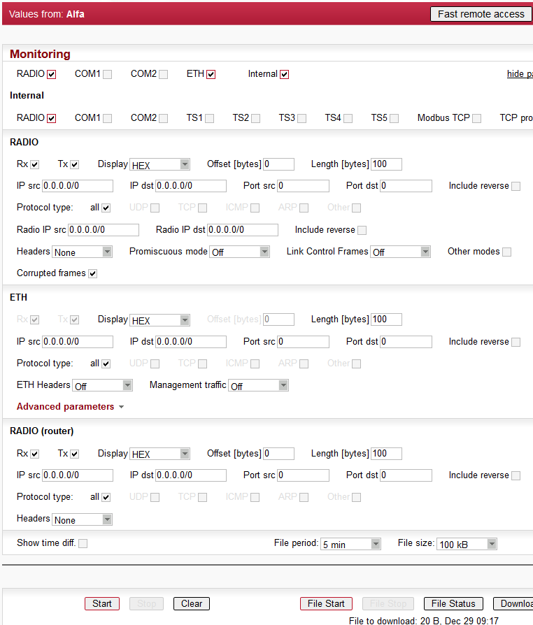
Monitoring is an advanced on-line diagnostic tool, which enables a detailed analysis of
communication over any of the RipEX router interfaces. In addition to all the physical
interfaces (RADIO, ETH, COM1, COM2), some internal interfaces between software modules can
be monitored when such advanced diagnostics is needed.
Monitoring output can be
viewed on-line or saved to a file in the RipEX (e.g. a remote RipEX) and downloaded
later.
Please find Internal interfaces explanation later in this description.
A short demonstration of a monitoring message:
07:55:04.661446 [COM1:phy:Rx] length 2
        0x0000:  aaaa
07:55:04.674861 [RF:phy:Tx] (88) IP 192.168.141.213.8881>192.168.141.214.8882: UDP,length 32
        0x0000:  0800 4500 001e 0000 4000 4011 9dd2 c0a8
        0x0010:  8dd5 c0a8 8dd6 22b1 22b2 000a 72cf aaaa
Examples of more complex monitoring outputs can be found later in this description.
Tick boxes:
RADIO, COM1, COM2, ETH, Internal
When ticked, the setting for the respective interface(s) is enabled. When the “Internal” interface is ticked, another set of interface tick-boxes appears as follows:Internal:
RADIO, COM1, COM2, TS1, TS2, TS3, TS4, TS5, Modbus TCP, TCP proxy
When ticked, the setting for the respective internal interface(s) is enabled (see the description below).Common parameters for all interfaces:
Rx Tx
Tick boxes.
When ticked, packets (frames, messages) coming in the respective direction are monitored. A packet is considered a Tx one when it comes out from the respective software module (e.g. RADIO or Terminal Server) and vice versa. When an external interface (e.g. COM:phy) is monitored, the Tx also means packets being transmitted from the RipEX over the respective interface (Rx means “received”). Understanding the directions over the internal interfaces may not be that straightforward, please consult the diagram below for clarification.
A packet is considered a Tx one when it comes out from the respective software module (e.g. RADIO or Terminal Server) and vice versa. When an external interface (e.g. COM(phy)) is monitored, the Tx also means packets being transmitted from the RipEX over the respective interface (Rx means “received”}. Understanding the directions over the internal interfaces may not be that straightforward, please consult the diagram below for clarification. Please note the separate monitoring of Rx or Tx frames is not possible at the ETH interface.Display
List box: HEX, HEX+ASCII, ASCII
Default = HEX
The format of monitoring output.Offset [bytes]
Default = 0
Number of bytes from the beginning of packet/frame, which will not be displayed. The Length of bytes will be displayed starting from the immediately next byte.
This feature is not available at the ETH interface.Length [bytes]
Default = 100
Number of bytes, which will be displayed from each packet/frame.Example: Offset=2, Length=4 means, that bytes from the 3rd byte to the 6th (inclusive) will be displayed:
Data (HEX):01AB3798A28593CD6B96
Monitoring output:3798A285
Filter parameters for IP/ARP packets
Available for RADIO, ETH and Internal RADIO (router), COMn(router), TSn(router), Modbus TCP(router), TCP proxy (TCP), TCP proxy(router):
IP src
IP source address range in the following format:aaa.bbb.ccc.ddd/maskIP dst
IP destination address range in the following format:aaa.bbb.ccc.ddd/maskPort src
TCP/UDP source port (range) in the following format:aaaa(-bbbb)Port dst
TCP/UDP destination port (range) in the following format:aaaa(-bbbb)Include reverse
Tick box.
When ticked, the frames defined by the IP src (or the IP dst) and the Port src (or the Port dst) will be displayed from both route directions, i.e. any „src” value is used as a „dst” as well (and vice-versa) by the filter.Protocol type
(available for RADIO, ETH and Internal RADIO (router))
Tick boxes for displaying specific protocols only. “Other” means displaying everything except the four listed protocols (even non-IP frames in case of the RADIO interface).
Interface specific parameters – RADIO
Radio IP src
The Radio IP source address of the frame has to be within the range defined: aaa.bbb.ccc.ddd/mask.Radio IP dst
The Radio IP destination address of the frame has to be within the range defined: aaa.bbb.ccc.ddd/mask.Headers:
List box: None, Radio Link, Data Coding, Both
Default = NoneNone – only the Radio Link Protocol data is displayed
Radio Link – Radio Link Control Header is displayed. It contains e.g. frame type, No., Radio MAC addresses etc.
Data Coding – Data Coding Header is displayed. It contains information on data part compression, fragmentation and encryption.
Both – Both the above mentioned headers are displayed.
Note that it may be quite difficult to locate the original payload in the data part of a Radio Link Protocol frame. Depending on the operation mode (Bridge vs. Router) and the interface used by the application (ETH, COM, Terminal Server…), different protocol headers (ETH, IP, UDP…) may be present and the whole data part may be compressed and encrypted.
Promiscuous mode:
List box: On, Off
Default = OffOff – only frames which are normally received by this unit, i.e. frames whose Radio IP destination equals to Radio IP address of this RipEX unit and broadcast frames are processed further by monitoring filters.
On – all frames detected on the Radio channel are passed to monitoring filters
Link Control Frames
List box: On, Off
Default = OffOff – Radio Link Control Frames (e.g. ACK frames) are never displayed.
On – Radio Link Control Frames which pass the other monitoring filters are displayed
Other modes
Tick boxes.
When RADIO interface is in the Promiscuous mode, the unit is capable to monitor (receive) the frames which are transmitted in different operation modes (Bridge x Router) from the one set in this unit. Although such frames cannot be fully analysed by the monitoring engine, their content is displayed when the corresponding mode tick box is ticked. Note that only the applicable tick box is visible, i.e. when Operating mode is Router, than Bridge mode tick box and vice versa.Rx stream
Tick box.
When ticked, received stream mode frames are included in the monitoring output. Applies to Bridge mode with Stream mode frame closing only. Warning : Stream mode traffic typically consists of large number of short frames, hence excessive amount of monitoring data may be generated. Note that TX frames in stream mode are not monitored.Corrupted frames
Tick box.
Default = Ticked
When un-ticked, the corrupted (“header CRC error”, “data CRC error”, etc.) received frames are not displayed. This may be useful when the communication in the channel is heavily disturbed by interference or noise, resulting in „garbage” messages which can make the monitoring output difficult to read.
Interface specific parameters – ETH
ETH Headers
List box: On, Off
Default = Off
When On, the ETH header is included in the monitoring output. Otherwise only the IP packet is displayed.
NOTE: When VLAN ID of VLAN packets is required to be displayed, ETH Headers must be “On”.Management traffic
List box: On, Off
Default=Off
When Off, datagrams to and from HTTPS, HTTP and SSH ports in this unit are not monitored. This avoids monitoring loop under normal circumstances, i.e. when the on-line monitoring is viewed on local PC connected via the ETH interface.Advanced parameters:
User rule
The standard tcpdump program is used for ETH monitoring. An arbitrary user rule in tcpdump syntax can be written in the text box. The rule is then added after the rules generated from the filters set for the ETH interface on this web page.NOTE: Not all general rules are supported. When unsupported or wrong syntaxes are used, the warning (ETH monitoring terminated. Invalid tcpdump parameters?) will be displayed.
Headers:
List box: None, Packet (IP), Frame (ETH)
Default: NoneNone – Only the payload data is displayed, e.g. the data part of a UDP datagram.
Packet (IP) – Headers up to Packet layer are included, i.e. the full IP packet is displayed.
Frame (ETH) – The full Ethernet frame is displayed, i.e. including the ETH header.
Show time diff.
Tick box.
Default = Unticked
When ticked, the time difference between subsequent packets is displayed in the monitoring output.File period
List box: 1 min, 2 min, 5 min, 10 min, 20 min, 30 min, 1 hour, 3 hours, 24 hours, Off
Default = 5 minFile size
List box: 1 KB, 10 KB, 50 KB, 100 KB, 500 KB, 1 MB, max (~2 MB)
Default = 100 KB
Upon clicking the “File start” button, the file is cleared and the monitoring output is copied into it. When the selected “File period” expires or the “File size” has been reached, whichever event occurs first, the file is closed and left waiting to be downloaded later. The start and stop of monitoring to file is independent of the on-line monitoring, i.e. the monitoring output is recorded even when the on-line monitoring is stopped.
Buttons located at the bottom of the monitoring screen come in two groups:
left: , , buttons, which control the on-line monitoring, and
right: , , , buttons, which control the recording into the file.
The two processes can be started/stopped by the respective buttons independently any time. Only one of the / (/) button pair is accessible at a time, depending on the status of the respective monitoring process (the other button is gray).
The button clears the screen with on-line monitoring output, even when the monitoring is running at the moment.
The button refreshes the status of the file which is stored in RipEX and of the recording process. It is recommended to use this button whenever you can not be sure whether your browser is synchronized with the server in the RipEX.
The button invokes the Download File dialog.
Whenever the or button is activated, the current settings of the monitoring from your web page are applied. When you change any setting on the page, both Start and File Start buttons indicate that a change has been made. They turn red when the respective monitoring process is idle and they change into Apply button when the monitoring is running, i.e. when the respective Start (File Start) button has been gray. Clicking the Apply button enforces the configuration change (e.g. adding one more interface) to the running monitoring processInternal interfaces description
Internal interfaces are the interfaces between a SW module and the central router module. All these interfaces can be found in next figure:
The Router and Bridge module acts as a standard IP router or bridge, i.e. decides to which interface an IP packet goes next.
The COM ports module does the conversion from messages received over the serial ports to UDP datagrams and vice-versa.
The Radio channel module wraps (unwraps) IP packets into radio channel frames and handles all sorts of service frames.
The Terminal servers process messages from/to virtual COM ports, transforming them into/from the same UDP datagrams as the COM port module does.
The Modbus TCP server similarly processes packets of Modbus TCP(RTU) protocol – see the relevant application note (Modbus TCP/RTU) for details. Since it is possible to monitor the messages from virtual COM and the resulting UDP datagrams independently, the TSn and the Modbus TCP have two internal interfaces – distinguished as (com) and (router).
The TCP proxy server converts TCP datagrams to UDP ones, while maintaining the original TCP session locally. The two internal interfaces can be used to independently monitor the TCP and UDP sides on the (com) and (router), respectively.
MP1, MP2, … labels are the monitoring points referred to in following Monitoring examples.
Modulation and Coding listing description
The information about RF channel Modulation and Coding can be found in the RF channel monitoring:
12:26:34.734036 [RF:phy:Tx] (84) IP 192.168.141.213.8881 > 192.168.141.215.8882: UDP,len 32
 RLhead:  4e80 01ac c701 ae0f 21 ((MC:10) 10.10.10.213 > 10.10.10.214, |LN:4|P:0|A:y|R:-|)
The “(MC:xy)” part of message brings Modulation and Coding level:
“x” Modulation
0x0 = 2-CPFSK (default)
0x1 = 4-CPFSK
0x8 = DPSK
0x9 = pi/4-DQPSK
0xA = 8DPSK
0xB = 16-DEQAM
“y” Coding
0x0 = FEC Off (default)
0x1 = FEC On
12:26:34.734036timestamp
[RF:phy:Tx] (MP3)interface monitored
[MC10]1 = 4-CPFSK, 0 = FEC Off (default)
Monitoring examples – COM, RADIO
The hexadecimal data
aaaais coming through the port COM1 and then the frame is sent over the radio channel. Monitored on IP address 192.168.141.213:
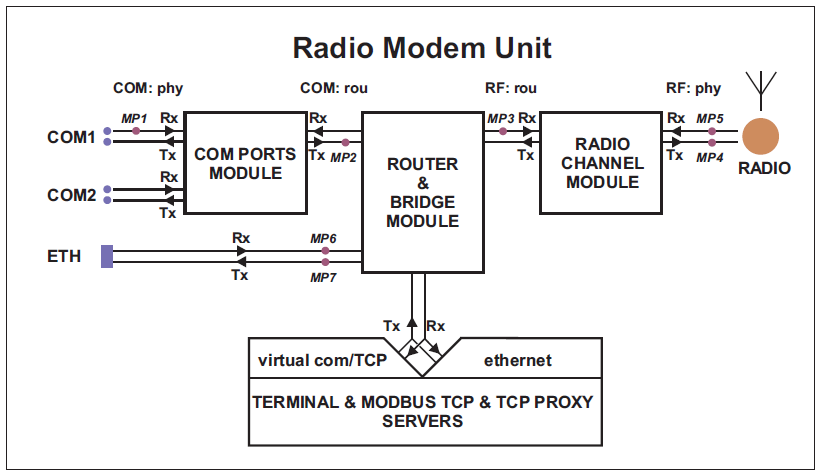
07:55:04.661446 [COM1:phy:Rx] length 2
        0x0000:  aaaa
07:55:04.674861 [RF:phy:Tx] (88) IP 192.168.141.213.8881>192.168.141.214.8882: UDP,length 32
        0x0000:  0800 4500 001e 0000 4000 4011 9dd2 c0a8
        0x0010:  8dd5 c0a8 8dd6 22b1 22b2 000a 72cf aaaa
| timestamp – |
| interface monitored – |
| monitored frame length [bytes] |
| monitored frame position, Byte increments, hexadecimal |
| monitored frame |
| timestamp |
| interface monitored – |
| physical layer Tx frame number |
| SRC IP address and UDP port number |
| DST IP address and UDP port number |
| Ethernet Protocol type |
| monitored frame length [bytes] |
| monitored frame report position, Byte increments, hexadecimal |
| monitored frame report |
NOTE: (MP1),(MP4) are the monitoring points as described in
Fig. 7.19, “Interfaces”
Monitoring including internal interfaces. Monitored on IP address 192.168.141.213:
12:26:34.700971 [COM1:phy:Rx] length 2
 0x0000:  aaaa
12:26:34.701476 [COM1:rou:Tx] IP 0.0.0.0.8881 > 192.168.141.215.8882: UDP, length 0+2
 0x0000:  aaaa
12:26:34.702074 [RF:rou:Rx] IP 192.168.141.213.8881 > 192.168.141.215.8882: UDP, length 28+2
 0x0000:  4500 001e aa0f 0000 4011 33c2 c0a8 8dd5
 0x0010:  c0a8 8dd7 22b1 22b2 000a 72ce aaaa
12:26:34.734036 [RF:phy:Tx] (84) IP 192.168.141.213.8881 > 192.168.141.215.8882: UDP,len 32
 RLhead:  4e80 01ac c701 ae0f 21 ((MC:10) 10.10.10.213 > 10.10.10.214, |LN:4|P:0|A:y|R:-|)
 0x0000:  0800 4500 001e aa0f 0000 4011 33c2 c0a8
 0x0010:  8dd5 c0a8 8dd7 22b1 22b2 000a 72ce aaaa
12:26:34.748841 [RF:phy:Rx] (84) ACK, rss:52 dq:238
 RLhead:  4000 ae0f 21
| frame incoming through physical interface |
| monitored frame report |
| packet sent from the COM PORT module to the ROUTER module |
| the source port does not have an IP address, only port number
8881 |
| the destination IP and port depends on the com port protocol setting |
| monitored frame report, data transmitted over the radio channel can be shortened (it depends on the COM port protocol) |
| packet received by the radio channel module from router module |
| source IP address and port |
| destination IP address and port given by Async Link protocol |
| overhead length + data length |
| frame sent from the radio channel module to the antenna |
| radio channel transmitted frames internal numbering |
| Radio Link header (enable “RADIO/Headers” = Radio Link) |
| transmitting radio channel IP address |
| receiving radio channel IP address (according to the Routing table) |
| Acknowledgement frame (ACK) reception |
| ACK frame number is the same as the acknowledged frame number |
|
Ethernet frame received and transmitted via radio. Monitored on IP address 192.168.141.213:
08:23:19.197235 [ETH] ARP, Request who-has 192.168.141.214 tell 192.168.141.212, length 46
 0x0000:  0001 0800 0604 0001 0002 a949 c067 c0a8
 0x0010:  8dd4 0000 0000 0000 c0a8 8dd6 0000 0904
 0x0020:  690f 5600 aaaa 1234 ffff ffff ffff

08:23:19.930106 [ETH] ARP, Reply 192.168.141.214 is-at 00:02:a9:ae:0b:39, length 28
 0x0000:  0001 0800 0604 0002 0002 a9ae 0b39 c0a8
 0x0010:  8dd6 0002 a949 c067 c0a8 8dd4

08:23:20.441093 [ETH] IP 192.168.141.212.8888 > 192.168.141.214.8001: UDP, length 10
 0x0000:  4500 0026 0002 4000 4011 9dc9 c0a8 8dd4
 0x0010:  c0a8 8dd6 22b8 1f41 0012 ae15 0000 0905
 0x0020:  690f 5600 aaaa 0000 0000 0000 0000

08:23:20.443997 [RF:rou:Rx] IP 192.168.141.212.8888 > 192.168.141.214.8001: UDP, length 28+10
 0x0000:  4500 0026 0002 4000 3f11 9ec9 c0a8 8dd4
 0x0010:  c0a8 8dd6 22b8 1f41 0012 ae15 0000 0905
 0x0020:  690f 5600 aaaa

08:23:20.479097 [RF:phy:Tx] (88) IP 192.168.141.212.8888 > 192.168.141.214.8001: UDP,len 40
 RLhead:  4ea0 01ac c701 ae0f 21 ((MC:10) 10.10.10.213 > 10.10.10.214, |LN:5|P:0|A:y|R:-|)
 0x0000:  0800 4500 0026 0002 4000 3f11 9ec9 c0a8
 0x0010:  8dd4 c0a8 8dd6 22b8 1f41 0012 ae15 0000
 0x0020:  0905 690f 5600 aaaa

08:23:20.493823 [RF:phy:Rx] (88) ACK, rss:50 dq:235
 RLhead:  4000 ae0f 21
| ARP Request received |
| ARP Reply transmitted |
| frame received from the ETH device |
| ETH frame source IP address and port |
| ETH frame destination IP address and port |
| packet received by the Radio ch. module from the Router module |
| frame sent from the Radio channel module to the antenna |
| source IP address and port, same as the incoming ETH frame |
| destination IP address and port, same as the incoming ETH frame |
| transmitting radio channel IP address |
| receiving radio channel IP address (according to the Routing table) |
| receipt of the confirmation frame (ACK) |
Internal Errors and Warning displayed by monitoring
Errors (red background)
Requested monitoring data missing
Required data for monitoring are not available for an unknown reason.Can be displayed on an independent line while any interface is being monitored.
RF preheader error
“RF-preheader” is a part of header transmitted by the most robust modulation.Displayed while “RADIO” (Rx) interface is being monitored as part of a packet header.
RL header CRC error
“RL-header” is Radio Link protocol header.Displayed while “RADIO” (Rx) interface is being monitored as part of a packet header.
Bridge stream datablock header CRC error
“Bridge stream DB-header” is header of Data block transmitted while Operating mode is Bridge and Frame closing (COM) is Stream.Displayed while “RADIO” (Rx) interface is monitored as part of a packet header.
Data CRC error
Data CRC error.Displayed while “RADIO” (Rx) interface is monitored as part of a packet header.
Warnings (yellow background)
Record sequence problem – reconfiguration?
There is a problem in sequence of records. The system may have to be reconfigured with other Settings or Routing pages.Can be displayed on an independent line while any interface is being monitored.
Record sequence problem. Some records may be lost.
There is a problem in sequence of records for an unknown reason. One or more records have been lost.Can be displayed on an independent line while any interface is being monitored.
[x] missing record(s) detected
“x” (replaced by specific number) records are missing.Can be displayed on an independent line while any interface is being monitored.
Monitoring restarted. Some records may be lost.
Monitoring system has been restarted e.g. because of monitoring configuration change. Some records may be lost.Can be displayed on an independent line while any interface is being monitored.
ETH monitoring terminated. Invalid tcpdump parameters?
Monitoring of ETH interface has been stopped. Probably because of unsupported or wrong ‘tcpdump’ syntax in Monitoring/ETH/Advanced parameters/User rule.Can be displayed on an independent line while ETH interface is being monitored.
Interface not ready!
RF interface is not ready. May happen when system is booting, after reconfiguration, after radio part recalibration made automatically after some time etc. The packet is discarded.Displayed while “RADIO” (Tx) interface is being monitored as part of a packet header.
RF interface not ready!
RF interface is not ready. May happen when system is booting, after reconfiguration, after radio part recalibration made automatically after some time etc. The packet is discarded.Displayed while “Internal-RADIO” (Tx) interface is being monitored as part of a packet header.
Interface not ready – high radio board temperature!
The transmitting is blocked because radio board has reached a temperature higher than 95 °C.Displayed while “RADIO” (Tx) interface is being monitored as part of a packet header.
RF interface not ready – high radio board temperature!
The transmitting is blocked because radio board has reached a temperature higher than 95 °C.Displayed while “Internal-RADIO” (Tx) interface is being monitored as part of a packet header.
Frame reception cancelled
The process of frame reception has been interrupted.Displayed while “RADIO” (Rx) interface is being monitored as part of a packet header.
Duplicated frame
Duplicated frame has been detected. It is discarded.Displayed while “RADIO” (Rx) interface is being monitored as part of a packet header.
Queue full
Radio interface Tx queues are full and next request for frame transmitting has been received. The frame is discarded.Displayed while “RADIO” (Tx) interface is being monitored as part of a packet header.
Incompatible frame?
Incompatible frame has been received. A few of the possible causes may be foreign RL-protocol, unknown RLP packet type, unknown RLP packet group, unknown service, incorrect ETH frame, unsupported IP frame type, …Displayed while “RADIO” (Rx) interface is being monitored as part of a packet header.
ACK
Unexpected ACK received.Displayed while “RADIO” (Rx) interface is being monitored as part of packet header.
Can’t decrypt – configuration problem?
The frame cannot be decrypted. Probably wrong configuration, e.g. different AES encryption keys are used.Displayed while “RADIO” (Rx) interface is being monitored as part of a packet header.
Can’t decrypt
The frame cannot be decrypted.Displayed while “RADIO” (Rx) interface is being monitored as part of a packet header.
Can’t decompress
The frame cannot be decompressed. (The compression is done automatically and can be switched off only over the CLI).Displayed while “RADIO” (Rx) interface is being monitored as part of a packet header.
Bridge mode frame
The frame in “Bridge” format has been received, but Operating mode is set to Router.Displayed while “RADIO” (Rx) interface is being monitored as part of a packet header.
Stream mode frame
The frame in “Bridge/Stream” format has been received, but Operating mode is not Bridge or Frame closing (COM) is not Stream.Displayed while “RADIO” (Rx) interface is being monitored as part of a packet header.
Router mode frame
The frame in “Router” format has been received, but Operating mode is set to Bridge.Displayed while “RADIO” (Rx) interface is being monitored as part of a packet header.
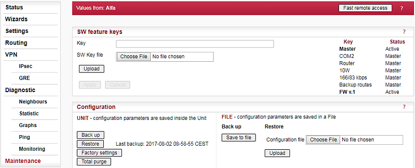
Certain advanced RipEX features have to be activated by software keys. On the right side
one may see the list of available keys and their respective status values.
Possible status values are:
Not present
Active
Active (timeout dd:hh:mm:ss) – the key can be time limited. For such a key, the remaining time of activity is displayed (1d 07:33:20). Time of activity of a key is counted only when the unit is switched on. Time limited key can be put on hold, i.e. temporarily deactivated. Press the corresponding Hold button (possibly several Hold buttons for several selected keys) and then press the Apply button to put the selected key(s) on hold.
On hold (timeout dd:hh:mm:ss) – the key is On hold, i.e. temporarily not active. To re-activate such a key, press the Activate and then Apply buttons.
Master – when Master key (unlocks all keys) is active.
Master (On hold) – The time-limited key for a specific feature is On hold, however the feature is active because of the Master key.
There are two ways to input the SW key into RipEX: Fill in the key you have received from or your distributor in the Key box using copy/paste or the SW key can be uploaded from a file. Fill in the SW Key file, or browse your disk in order to find the file. When a file is selected, it can be uploaded.
– when pressed, the selected SW key is uploaded into the RipEX, however it is not yet active. You can subsequently upload more keys.
Apply – when pressed, all the uploaded keys are activated and/or status values of Time limited keys are changed following their respective buttons Activate or Hold have been pressed. Afterwards the unit automatically reboots itself.
NOTE: SW feature key can be downloaded also from USB flash. Read details in the Firmware paragraph.
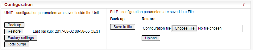
– Back up saves the active configuration into a backup file in the unit.
– configuration saved in the backup file in the unit is activated and the unit reboots itself.
– Sets the factory defaults and activates them. Neighbours, Statistic and Graphs databases are cleared including their histories. The unit reboots afterwards.
The following items are NOT cleared when the Factory settings are applied:
Admin password
Technical support package
Firmware archive
Configuration backup
SSL certificate (when your own certificate is used)
Remote access keys (when User key is used)
Folder /home/… in Linux
When you need to reset the device access parameters (the login, password, Ethernet IP etc.) to defaults, press the RESET button on the bottom-side of RipEX enclosure for 15 sec. See the User manual for details.
– sets the very same settings as when the device was delivered from the factory. I.e. Factory settings as above is applied and the flash memory is also totally cleared. I.e. the “not cleared” items in Factory settings are cleared by Total purge. The whole operation takes approx. 5 mins. and the unit is rebooted afterwards.
– saves the active configuration into a file.
Configuration can be uploaded from a file. Fill in the Configuration file, or browse your disk in order to find the file. When a file is selected, it can be uploaded.– uploads configuration from the selected file and activates it. The unit reboots itself afterwards.
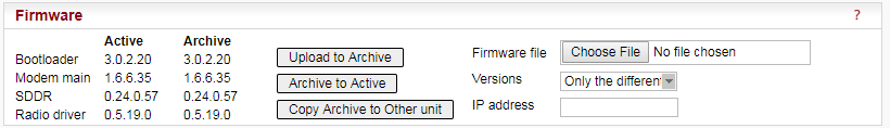
The firmware in the unit consists of several parts, however they come in one firmware package (file_name.cpio). Individual part names and their versions can be seen. There can be two versions of firmware packages stored within the unit – “Active” and “Archive”. Unit is always using the Active version. The Archive version is there just for convenience and safety of firmware manipulations. It can also be uploaded to a remote unit over the Radio channel.
– Fill in Firmware file, or browse your disk in order to find the file. When a file is selected and the “Upload to Archive” button pressed, it is uploaded and becomes the Archive firmware.
Note it is recommended to do this only over reliable Ethernet connections and not over the Radio channel.
– when pressed, the Active firmware is substituted by the Archive firmware. Either “All” or only “Only the different” versions are replaced according to the Versions list box setting. The unit reboots itself afterwards.
– he Archive firmware package can be copied to another unit typically over Radio channel. Fill in the IP address of the desired unit and press the button.
Note If possible, copy FW only over one Radio hop where radio link is quality sufficiently high. Otherwise it can be very time consuming. When Router mode is used, don’t forget to set correct Routing tables settings.
NOTE: New firmware as well as SW feature keys can be uploaded directly from a USB flash disk. Only FAT32 file system on flash disk is supported. Download firmware file from https://www.racom.eu . Save this file in the root directory of USB flash (in a format “ra1--<VERSION>.cpio”). When SW key(s) will be uploaded, save the respective file(s) also in the root directory with the file name(s) unchanged. More SW keys can be saved on a single flash disk. Remember that SW key is unique for each individual RipEX S/N. See the flash disc structure requirements in more details Section 5.2.5, “USB” .
When more than one fw files is on the flash disk, the most recent version is uploaded. The most recent version on the flash disk can not be older than in the RipEX; downgrade from flash is not supported. Upload from the flash is equivalent to Maintenance/Firmware/Upload to Archive plus Maintenance/Firmware/Versions=All plus Maintenance/Firmware/Archive to Active.
Plug USB flash with file(s) as above in RipEX USB connector, Status LED starts to blink
within 5 sec., it changes between green and red colors. When the LED blinks slowly (1x per
sec.), correct file(s) has been detected on flash.
NOTE: when LED blinks fast
(3x per sec.), expected files have not been found and USB flash can be removed.
Upload starts and Status LED can change its colors and blinking during upload. When upload is finished, the LED blinks fast (3x per sec.). USB flash can be removed.
The whole process can take up to 10 min. (FW approx. 8 min., SW key approx. 1 min.). There is a log(s) saved on USB disk (/logs) with information about upload process.
Don’t remove USB flash while uploading. USB flash could be damaged!
The Administrator account (user name “admin”) is the primary account for unrestricted unit configuration.
Password length is at least 5 and maximum 32 characters long. Only characters a-zA-Z0-9.:_- are allowed.
It is highly recommended to change default the password (admin) even if the user name remains always the same (admin). When the Apply button is pressed, the unit reboots.
– when pressed, the unit correctly shuts down and starts again (performs the cold start which equals to a power cycle). The reboot time is approx. 25 sec.
– when pressed, an ARP reply packet is broadcasted over the Radio channel. When e.g. a RipEX unit has been replaced by a spare one with the same Radio IP, but different Radio MAC address, the neighbouring RipEX units update their ARP tables only after their respective timeout expires. Forced transmission of an ARP reply restores the communication with the neighbours immediately.
NOTE: The ARP reply packet is automatically transmitted after every boot, hence the manual invocation should not be necessary. Nevertheless broadcasting an extra ARP reply following any IP or MAC address change is a good and recommended practice.
– when pressed, the current level of Received Signal Strength (one sample) on Radio channel is measured. This sample is measured regardless of the current Radio channel status (Quiet/Rx/Tx)
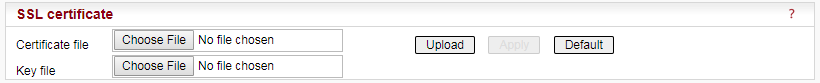
It is possible to download your own SSL certificate into RipEX for https communication used for web configuration. 2048 bits certificate is supported and recommended, however the 512 or 1024 bits certificates can also be used. SSL certificate may have one or two files. Both options are supported.
Certificate file
Fill in the Certificate file, or browse your disk in order to find the file.
Key file
When your SSL certificate consists of two files, fill in the Key file, or browse your
disk in order to find the file.
When file(s) is selected, it can be
uploaded.
– when pressed, the selected Certificate is uploaded into the RipEX, however it is not active yet.
– when pressed, the uploaded certificate is activated. Afterwards the unit automatically reboots itself.
– when pressed, the default SSL certificate is uploaded. To be activated, Apply button has to be executed.
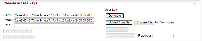
The “Fast remote access” is a secured communication channel over the Radio interface based on a modified ssh protocol. It is possible to use own security keys for this communication.
NOTE: It is not possible to use the Fast remote access between two RipEX units with different Remote access keys. When you want to change the Remote access key in a network, start from the most remote unit.
– Information only, the Active key is displayed here
– Information only, the Default key is displayed here
– Information only, the User key is displayed here after the Generate button has been pressed.
Activate User key
– when pressed, the User key displayed above is activated. When the User key is already active, the button is not active (grey).
Activate Default key
– when pressed, the Default key displayed above is activated. When the Default key is already active, the button is not active (grey).
There are several possibilities to create User key, which is displayed in the User box afterwards:
Generate
– the system generates a random User key. It is saved in the flash. This can be done only locally; this button is not active in the remote unit while using Fast remote access.Upload from file
– browse your disk in order to find the file with your User key and upload. This can be done only locally; this button is not active in the remote unit while using Fast remote access.Save to file
– the User key displayed in the box can be saved into a file. This can be done only locally and when the User key exists; this button is not active in the remote unit while using Fast remote.Copy to Other unit
– the User key displayed in the box is transferred to another unit in the network with the specified IP address. Afterwards it has to be activated in the remote unit manually. This button can be used also in the remote unit via Fast remote access. The button is not active when a User key doesn’t exist.

It is intended to be used for laboratory measurements or antenna testing.
Type
List box: Carrier, Random data
Carrier – only unmodulated carrier is transmitted
Random data – modulated random data is transmitted
Default = CarrierPeriod [s]
Default = 15 s (possible values 1s – 50s)
During this time period RipEX transmits after Start button is executed.
Technical support package is the file where some internal events are recorded. It can be used by technical support when a deeper diagnostic is required. The most recent part of it can be downloaded to the local PC.
Log depth
List box: possible values
Default = 500
This is the number of rows downloaded. The greater the number of rows, the longer the history to be found in the file. However more lines means greater file size as well. When downloaded from a remote unit over Radio channel in poor signal conditions, a lower Log depth should be selected.