RipEX is built into a rugged die-cast aluminium casing that allows for multiple installation possibilities, see Section 6.1.1, “DIN rail mounting”.
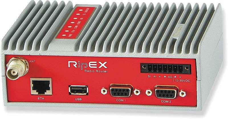
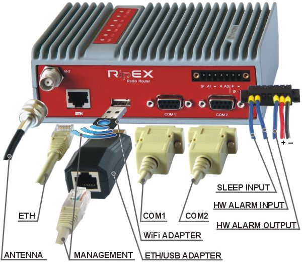
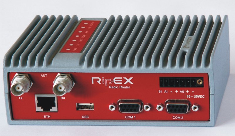
All connectors are located on the front panel. The upper side features an LED panel. The RESET button is located in an opening in the bottom side.
| Warning – hazardous locations | |
| Do not manipulate the RipEX (e.g. plug or unplug connectors) unless powered down or the area is known to be non-hazardous. |
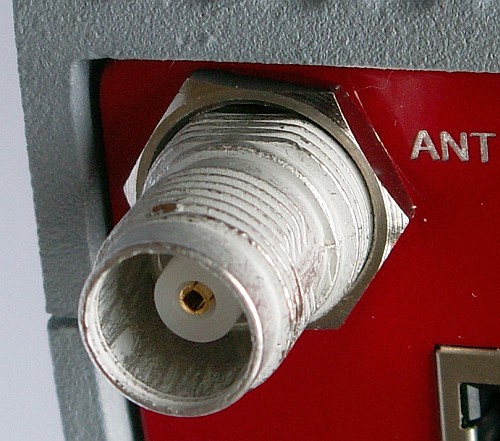
An antenna can connect to RipEX via TNC female 50Ω connector.
A model with two antenna connectors can be supplied to order, in which the Rx and Tx antennas are separate. This model is typically used on communication towers where one Rx and one Tx antennas are common for most devices.
See Section 5.5, “Model offerings”.
| Note | |
|---|---|
Frequency split (different Rx and Tx frequency) is independent from the presence of two antenna connectors. It can be set even on standard RipEX with one antenna connector. |
| Warning – hazardous locations | |
| Antenna has to be installed outside of the hazardous zone. |
Warning: RipEX radio modem may be damaged when operated without an antenna or a dummy load.
| Important | |
|---|---|
Coaxial overvoltage protection – antenna feeder should be secured with surge protection (lightning arrestor). We recommend to use DC block type surge protection, which can be found on ’s website. If any other type of surge protection is desired, we recommend to consult it with our technical support. |
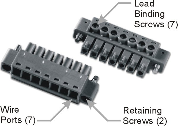
This rugged connector connects to a power supply and it contains control signals. A Plug with screw-terminals and retaining screws for power and control connector is supplied with each RipEX. It is Tyco 7 pin terminal block plug, part No. 1776192-7, contact pitch 3.81 mm. The connector is designed for electric wires with a cross section of 0.5 to 1.5 mm2. Strip the wire leads to 6 mm (1/4 inch). Isolated cables should receive PKC 108 or less end sleeves before they are inserted in the clip. Insert the cables in the wire ports, tightening securely.
Tab. 5.1: Pin assignment
| pin | labeled | signal |
|---|---|---|
| 1 | SI | SLEEP INPUT |
| 2 | AI | HW ALARM INPUT |
| 3 | − | −(GND) – for SLEEP IN, HW ALARM INPUT |
| 4 | + | +(POWER) – for HW ALARM OUTPUT |
| 5 | AO | HW ALARM OUTPUT |
| 6 | +10–30VDC | +POWER (10 to 30 V) |
| 7 | −10–30VDC | −POWER (GND) |
Pins 3 and 7, 4 and 6 are connected internally.
| Warning – hazardous locations | |
| The unit must be powered with an intrinsic save power source for use in hazardous locations. |
|
SLEEP INPUT SLEEP INPUT is the digital input for activating the Sleep mode. When this pin is grounded (for example when connected to pin 3), the RipEX switches into the Sleep mode. Using Power management (Advanced Config.), the Entering the Sleep mode can be delayed by a set time. Disconnecting SLEEP INPUT from GND (-) ends the Sleep mode. Note that RipEX takes 48 seconds to wake up from the Sleep mode. SLEEP INPUT can be also used for the wake-up from the Save state. For details see chapter (Advanced Config., Power management) |
 |
|
HW ALARM INPUT HW ALARM INPUT is a digital input. If grounded (e.g. by connecting to PIN 3), an external alarm is triggered. This alarm can be used for example to transmit information using SNMP Notification, informing for instance about a power outage or RTU problem. For details about Alarm management see chapter Advanced Configuration. |
 |
|
HW ALARM OUTPUT HW ALARM OUTPUT is a digital output. It can be activated in Alarm management settings, chapter Advanced Configuration. It may be used for instance to inform the connected RTU about a RipEX alarm or about the Unit ready status. If an alarm is triggered, HW ALARM OUTPUT is internally connected to GND. If the external device requires connection to positive terminal of the power supply, PIN 4 should be used. |
 |
POWER
The POWER pins labelled + and – serve to connect a power supply 10–30 VDC. The requirements for a power supply are defined in Section 5.4, “Technical specification”.
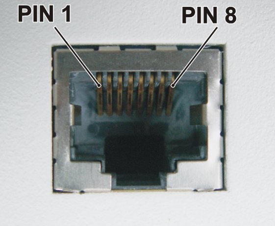
Standard RJ45 connector for Ethernet connection. RipEX has 10/100 BaseT Auto
MDI/MDIX interface so it can connect to 10 Mbps or 100 Mbps Ethernet network. The speed can
be selected manually or recognised automatically by RipEX. RipEX is
provided with Auto MDI/MDIX function which allows it to connect over both standard and cross
cables, adapting itself automatically.
Tab. 5.2: Ethernet to cable connector connections
| PIN | Signal | Direct cable | Crossed cable |
|---|---|---|---|
| 1 | TX+ | orange – white | green – white |
| 2 | TX− | orange | green |
| 3 | RX+ | green – white | orange – white |
| 4 | — | blue | blue |
| 5 | — | blue – white | blue – white |
| 6 | Rx− | green | orange |
| 7 | — | brown – white | brown – white |
| 8 | — | brown | brown |
RipEX provides two serial interfaces COM1 and COM2 terminated by DSUB9F connectors. COM1 is always RS232, COM2 can be configured as RS232 or RS485 (more in Adv. Conf., COM).
RipEX‘s RS232 is a hard-wired DCE (Data Communication Equipment) device.
Equipment connected to the RipEX’s serial ports should be DTE (Data Terminal
Equipment) and a straight-through cable should be used. If a DCE device is connected to the
RipEX‘s serial ports, a null modem adapter or cross cable has to be
used.
Tab. 5.3: COM1, 2 pin description
| DSUB9F | COM1, 2 – RS232 | COM2 – RS485 | ||
|---|---|---|---|---|
| pin | signal | In/ Out | signal | In/ Out |
| 1 | CD | Out | — | |
| 2 | RxD | Out | line B | In/Out |
| 3 | TxD | In | line A | In/Out |
| 4 | DTR | In | — | |
| 5 | GND | GND | ||
| 6 | DSR | Out | — | |
| 7 | RTS | In | — | |
| 8 | CTS | Out | — | |
| 9 | — | — | — | |
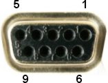
RipEX keeps pin 6 DSR at the level of 1 by RS232 standard permanently….
RipEX uses USB 1.1, Host A interface. USB interface is wired as
standard:
The USB interface is designed for the connection to an – external ETH/USB adapter or a Wifi adapter. They are optional accessories to RipEX, for more details see Section 4.3, “Connecting RipEX to a programming PC”. The adapters are used for service access to RipEX’s web configuration interface.
The USB interface can also be used for an external flash disc connection, which has been specifically designed to simplify complex maintenance tasks, so that these tasks can be performed by unqualified personnel in the field by simple plugging-in an USB stick and waiting until a LED flashes.
The USB connector also provides power supply (5 V/ 0.5 A). It can be used to temporarily power a connected device, for instance a telephone. The USB connector should not be used as permanent source of power supply.
| Note – hazardous locations | |
| Only USB equipments dedicated for hazardous locations shall remain connected permanently. |
An external USB flash disc can be used for firmware upgrade, SW keys upload, configuration backup and restore, ssl certificate and ssh keys upload and tech-support package download. Any common USB stick with several megabytes of free space can be used for these tasks.
| Note | |
|---|---|
The flash disc has to contain the FAT32 file system (the most common one at the time of writing). Any other file system will be simply ignored by the RipEX. When in doubt, consult your IT expert. |
Once the RipEX recognizes a flash disc inserted into the USB interface, the status LED starts blinking slowly, alternating red and green colors. That indicates the start of the upload/download of files. The LED flashing may change during the process, the successful completion of the recording is indicated by fast alternating green and red flashes (about 3 times per second). Note that it may take up to 10 minutes (when an FW upgrade is performed).
| Warning | |
|---|---|
NEVER unplug the USB disc before the proper (fast) flashing of the status LED starts! You may damage your disc otherwise. |
Following a successful detection of a USB flash disc, the RipEX writes the tech-support package, log files and the configuration text file to it. Then the README.txt file, which contains all the necessary information on the structure and names of files and directories, is written into the root directory of the disc. Please follow the detailed instructions in that file, or read it below:
Required FLASH structure:
for single radiomodem upgrade:
/ra1--<VERSION>.cpio firmware package(s), newest version is used /swkey/ directory with SW keys *_<SERNO>_*.txt SW key(s) /config.txt new configuration in text form /web.pem new Web certificate (complete or first part) /web.key second part of Web certificate (if necessary) /admin.pub new CLI key /rmtaccess.key new remote access key for upgrade of multiple radiomodems:
/ra1--<VERSION>.cpio firmware package, newest version is used /swkey/ directory with SW keys *_<SERNO>_*.txt SW key(s) /cnf/ directory with new configurations <SERNO>_*_config.txt new configuration(s) in text form /web.pem new Web certificate (complete or first part) /web.key second part of Web certificate (if necessary) /admin.pub new CLI key /rmtaccess.key new remote access key
All files/directories are optional, depending on the scope of upgrade. If no files are present, only data gathering will be performed.
| Note | |
|---|---|
Whenever an FW file (.cpio) is found in the root directory of the disc, the upgrade is executed automatically, regardless of the version of the currently active FW. If more than one FW file is found, the latest version is used. Remember to remove the FW files from the disk root when you do not intend to perform an upgrade. The same principles apply to a configuration update from the disc. |
Created files:
| /RipEX_README.txt | README file |
| /cnf_archive/ | directory with archived configurations |
| <SERNO>_<NAME>_config.txt | archived configuration(s) in text form |
| /logs/ | directory with log files |
| log_<SERNO>.txt | log file(s) |
| /tech_support/ | directory with technical support packages |
| <SERNO>_<NAME>_tsupport.tgz | technical support package(s) |
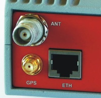
RipEX.can be equipped with an internal GPS, see Section 5.5, “Model offerings”. The GPS module is used for time synchronisation of the NTP server inside RipEX. See Adv. Conf., Time for more. In this case the front panel contains a SMA female 50 ohm connector for connecting the GPS antenna.
active or passive antenna
3.3 VDC supply
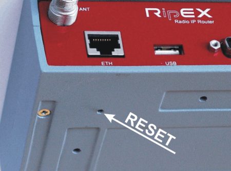
A reset button is situated on the underside of each RipEX unit. The button support
multiple functions. Each function is activated dependant on how long the reset button is
depressed. The “Physical security” parameter in Settings/Device/Management menu dictates the behavior
features available when depressing the button.
Physical security = Off:
When button is
depressed
| Time [seconds] | Status LED action | Action if button released |
|---|---|---|
| 0 – 5 | Goes dark | — |
| 5 – 15 | Flashes Green | Device reboot |
| 15 – 18 | Flashes Green faster | Default access settings, reboot |
| 30 – 33 | Flashes Red faster | Factory Settings, reboot |
Physical security = On:
When button is
depressed
| Time [seconds] | Status LED action | Action if button released |
|---|---|---|
| 0 – 5 | Goes dark | — |
| 5 – 15 | Flashes Green | Device reboot |
| 15 – 18 | Flashes Green faster | Total purge, reboot |
| ETH IP and Mask: ETH Default GW: ETH Speed: DHCP: ARP proxy & VLAN: Firewall: Hot Standby: Routing table: Management: Username: Password: | 192.168.169.169/24 0.0.0.0 Auto Off Off Off Off Deleted Default (Web server=HTTP+HTTPS, CLI=SSH) admin admin |
| Note | |
|---|---|
To reset the RipEX only use the RESET button as described above or use the button in RipEX’s web configuration, see Adv. Conf., Maintenance. Never use a power cycling (disconnecting and reconnecting power supply) to reset it. While power cycle resets, or rather reboots the RipEX, its software will not terminate correctly resulting in logs, statistics and graphs not being saved properly. |
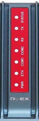
Tab. 5.5: Key to LEDs
| Color | Description | |
|---|---|---|
| STATUS | Green | The RipEX OS (Linux) is running successfully |
| Dark | Reset button has been pressed | |
| Green flashes slowly | reset after five-seconds pressing the Reset button | |
| Green flashes quickly | default access after 15-seconds pressing the Reset button | |
| Red flashes quickly | Emergency | |
| Red | Alarm | |
| TX | Green blinks with a period of 1 sec | GPS module synchronized, for RipEX-xxxG model only |
| Red | transmitting to radio channel | |
| RX | Green | receiver is synchronised to a packet |
| Yellow | there is a signal stronger than −80 dBm on Radio channel | |
| COM2 | Green | data receiving |
| Yellow | data transmitting | |
| COM1 | Green | data receiving |
| Yellow | data transmitting | |
| ETH | Yellow ON | 100 Mb/s speed |
| Yellow OFF | 10 Mb/s speed | |
| Green ON | connected | |
| Green flashes | Ethernet data | |
| PWR | Green | powered successfully |
| Blinks with a period of 1 sec | Save mode | |
| Flashes once per 3 sec | Sleep mode |
Alarm | – is “On” when any controlled item in Alarm management, (see Adv. Conf., Alarm management for more) is in alarm status (out of thresholds) and “SNMP Notification”, “HW Alarm Output” or “Detail graphs start” for any line in the Alarm configuration table are checked. |
Emergency | – Emergency status is an undefined RipEX status either because of a SW or HW problem when RipEX does not function properly. Maintenance web page is mostly accessible even in Emergency status. If the problem cannot be eliminated after a power cycle, send the unit to for repair. |
Tab. 5.6: Technical parameters
| Radio parameters | ||||||||||||||
| Frequency bands | 135 – 154; 154 – 174 MHz 215 – 240 MHz 300 – 320; 320 – 340; 340 – 360 MHz 368 – 400; 400 – 432; 432 – 470 MHz 470 – 512 MHz 928 – 960 MHz see details | |||||||||||||
| Channel spacing | 6.25; 12.5; 25; 50 kHz 1) | |||||||||||||
| Frequency stability | ±1.0 ppm | |||||||||||||
| Modulation | QAM (linear): 16DEQAM; D8PSK; π/4DQPSK; DPSK | |||||||||||||
| FSK (exponential): 4CPFSK; 2CPFSK | see details | |||||||||||||
| FEC (Forward Error Correction) | On/Off, ¾ Trellis code with Viterbi soft-decoder | |||||||||||||
| Gross data rate (data speed) 2) |
| |||||||||||||
| Transmitter | ||||||||||||||
| RF Output power | QAM: 0.5 – 2 W
3) FSK: 0.1 – 10 W 4) see details | |||||||||||||
| Duty cycle | Continuous | |||||||||||||
| Rx to Tx Time | < 1.5 ms | |||||||||||||
| Intermodulation Attenuation | > 40 dB | |||||||||||||
| Spurious Emissions (Conducted) | < -36 dBm | |||||||||||||
| Radiated Spurious Emissions | < -36 dBm | |||||||||||||
| Adjacent channel power | < -60 dBc | |||||||||||||
| Transient adjacent channel power | < -60 dBc | |||||||||||||
| Receiver | ||||||||||||||
| Anti-aliasing Selectivity | 50 kHz @ -3 dB BW | |||||||||||||
| Tx to Rx Time | < 1.5 ms | |||||||||||||
| Maximum Receiver Input Power | 20 dBm (100 mW) | |||||||||||||
| Rx Spurious Emissions (Conducted) | < -57 dBm | |||||||||||||
| Radiated Spurious Emissions | < -57 dBm | |||||||||||||
| Blocking or desensitization | see details | |||||||||||||
| Spurious response rejection | > 70 dB | |||||||||||||
| 1) | 50 kHz channel spacing is HW dependent, versions before 2014 didn´t support it. 6.25 kHz channel spacing is not available for RipEX-928. | |||||||||||||
| 2) | Network throughput varies and depends heavily on the data structure, optimization effectivity, protocol on Radio channel, network topology, signal budgets and many other parameters of the network. Practical tests are recommended. | |||||||||||||
| 3) | Max peak envelope power (PEP) 7.0 W | |||||||||||||
| 4) | For output power 10 W it is recommended to use input power above 11 VDC. | |||||||||||||
| RipEX-470, RipEX-928 – max. RF Output power 8 W. | ||||||||||||||
| Electrical | ||||
| Primary power | 10 to 30 VDC, negative GND | |||
| Rx | 5 W / 13.8 V; 4.8 W / 24 V; (Radio part < 2 W) | |||
| Tx | 13 – 40 W, see details | |||
| Sleep mode | 0.1 W | |||
| Save mode | 2 W | |||
| Interfaces | ||||
| Ethernet | 10/100 Base-T Auto MDI/MDIX | RJ45 | ||
| COM1 | RS232 | DB9F | ||
| 300 – 115 200 b/s | ||||
| COM2 | RS232/RS485 SW configurable | DB9F | ||
| 300 – 115 200 b/s | ||||
| USB | USB 1.1 | Host A | ||
| Antenna | 50 Ω | TNC female | ||
| Inputs/Outputs | 1x HW alarm input 1x HW alarm output 1x Sleep input | Power connector | ||
| Indication LEDs | |||
| LED panel | 7× tri-color status LEDs (Power, ETH, COM1, COM2, Rx, Tx, Status) | ||
| Environmental | |||
| IP Code (Ingress Protection) | IP40, (IP51 – see details) | ||
| MTBF (Mean Time Between Failure) | > 900 000 hours (> 100 years) | ||
| Hazardous lodations | Ex II 3G Ex ic IIC T4 Gc | ||
| Operating temperature | −40 to +70 °C (−40 to +158 °F) | ||
| Operating humidity | 5 to 95 % non-condensing | ||
| Storage | −40 to +85 °C (−40 to +185 °F) / 5 to 95 % non-condensing | ||
| Mechanical | |||
| Casing | Rugged die-cast aluminium | ||
| Dimensions | H × W × D: 50 × 150 × 118 mm (1.97 × 5.9 × 4.65 in) | ||
| Weight | 1.1 kg (2.4 lbs) | ||
| Mounting | DIN rail, L-bracket, Flat-bracket, 19″ Rack shelf | ||
| SW | |||
| Operating modes | Bridge / Router | ||
| Radio channel protocols | Transparent @ Bridge Base driven, Flexible @ Router see details | ||
| User protocols on COM |
Modbus, IEC101, DNP3, PR2000, UNI, Comli, DF1, RP570, Profibus, … | ||
| User protocols on Ethernet | Modbus TCP, IEC104, DNP3 TCP, Comli TCP,
Terminal server… | ||
| Serial to IP convertors | Modbus RTU / Modbus TCP, DNP3 / DNP3 TCP | ||
| Protocol on Radio channel | |||
| Multi master applications | Yes | ||
| Report by exception | Yes | ||
| Collision Avoidance Capability | Yes | ||
| Remote to Remote communication | Yes | ||
| Addressed & acknowledged serial SCADA protocols | Yes | ||
| Data integrity control | CRC 32 | ||
| Optimization | Payload data and Ethernet / IP / TCP / UDP header compression, Packet flow on Radio channel optimization | ||
| Security | |||
| Management | HTTP, HTTPS (own certificate), SSH | ||
| Access accounts | 2 levels (Guest, Admin) | ||
| Encryption | AES256-CCM | ||
| VPN | IPsec, GRE | ||
| VLAN | IEEE 802.1Q (tagging), Q-in-Q for Transparent mode | ||
| Firewall | Layer 2 – MAC, Layer 3 – IP, Layer 4 – TCP/UDP | ||
| Diagnostic and Management | |||
| Radio link testing | Yes (ping with RSS, Data Quality, Homogeneity) | ||
| Watched values (Can be broadcast to neighbouring units. Received info displayed in Neighbours table) | Device – Ucc, Temp, PWR, VSWR, *HW Alarm
Input. Radio channel – *RSScom, *DQcom, TXLost [%] User interfaces – ETH (Rx/Tx), COM1 (Rx/Tx), COM2 (Rx/Tx) * not broadcast | ||
| Statistics | For Rx/Tx Packets on User interfaces (ETH, COM1, COM2) and for User data and Radio protocol (Repeats, Lost, ACK etc.) on Radio channel | ||
| Graphs | For Watched values and Statistics | ||
| History (Statistics, Neighbours, Graphs) | 20 periods (configurable, e.g. days) | ||
| SNMP | SNMPv1, SNMPv2c, SNMPv3 SNMP Traps or SNMP Informs generation for Watched values | ||
| NTP | Client, Server (synchronized from internal GPS) | ||
| Monitoring | Real time/Save to file analysis of all physical interfaces (RADIO, ETH, COM1, COM2) and some internal interfaces between software modules (e.g. Terminal servers, Modbus TCP server etc.) | ||
| Standards | |
| CE | RED, RoHS, WEEE |
| FCC, IC | FCC Part 90, Pending: IC RSS-119 |
| Spectrum | ETSI EN 302 561 V2.1.1:2017 ETSI EN 300 113 V2.2.1:2017 |
| EMC (electromagnetic compatibility) | ETSI EN 301 489-1 V2.1.1:2017 ETSI EN 301 489-5 V2.1.1:2017 IEC 1613:2009 Class 1 |
| Safety | EN 60950-1:2006, A11:2009, A1:2010, A1:2010, A12:2011, A2:2013 |
| SAR | EN 50385:2002 EN 50383ed.2:2011 |
| Vibration & shock | EN 61373:1999 EN 60068-2-6:2008 |
| Seismic qualification | IEC 980:1989 (seismic category 1a) |
| Hazardous locations | EN 60079-0:2012 EN 60079-11:2012 |
| IP rating | EN 60529:1993 + A1:2001 + A2:2014 |
Tab. 5.7: Maximal power for individual modulations
| RipEX | |||
| Modulation | PEP [dBm] | RMS [dBm] | RMS [W] |
| 2CPFSK | 20 – 40 | 20 – 40 | 0.1 – 10 |
| 4CPFSK | 20 – 40 | 20 – 40 | 0.1 – 10 |
| DPSK | 20 – 36 | 27 – 33 | 0.5 – 2 |
| π/4-DQPSK | 20 – 36 | 27 – 33 | 0.5 – 2 |
| D8PSK | 20 – 37 | 27 – 33 | 0.5 – 2 |
| 16DEQAM | 20 – 38 | 27 – 33 | 0.5 – 2 |
| SW configurable RMS [W] FSK: 0.1 – 0.2 – 0.5 – 1.0 – 2.0 – 3.0 – 4.0 – 5.0 – 10 QAM: 0.5 – 1.0 – 2.0 | |||
| PEP vs. RMS application note | |||
Tab. 5.8: Sensitivity
| Modulation | 2CPFSK | 4CPFSK | DPSK | π/4DQPSK | D8PSK | 16DEQAM |
| Channel spacing | Sensitivity [dBm]@ BER 10-6, FEC 3/4 | |||||
| 6.25 | -114 | -111 | -113 | -112 | -104 | -103 |
| 12.5 | -113 | -108 | -110 | -109 | -101 | -99 |
| 25 | -111 | -107 | -109 | -107 | -101 | -99 |
| 50 | -107 | -101 | -105 | -100 | -96 | -95 |
Tab. 5.9: Recommended Cables
| Port | Recommended cables and accessories | Length |
|---|---|---|
| DC terminals – Power | V03VH-H 2×0,5 | Max. 3 m |
| SI (Sleep Input) | V03VH-H 1×0,5 | Max. 3 m |
| AI (Alarm Input) | V03VH-H 1×0,5 | Max. 3 m |
| AO (Alarm Output) | V03VH-H 1×0,5 | Max. 3 m |
| COM1 | LiYCY 4×0,14 | Max. 3 m |
| COM2 | LiYCY 4×0,14 | Max. 3 m |
| USB | USB to 10/100 Ethernet Adapter ADE-X5 | Max. 3 m |
| ETH | STP CAT 5e | As needed |
| Note – hazardous locations | |
| The cross sections mentioned in above table are the minimal cross sections used under hazardous location conditions. |
Tab. 5.10: Power consumption
| Tx – Exponential – FSK (4CPFSK, 2CPFSK) | RF power | Power consumption | ||
| 13.8 V | 24V | |||
| 0.1 W | 13.8 W | 13.2 W | ||
| 1 W | 15.2 W | 14.4 W | ||
| 5 W | 33.1 W | 31.2 W | ||
| 10 W | 41.4 W | 38.4 W | ||
| Tx – Linear – QAM (16DEQAM, D8PSK, π/4DQPSK) | 0.5 W | 30.4 W | 30 W | |
| 1 W | ||||
| 2 W | ||||
The very first parameter which is often required for consideration is the receiver sensitivity. Anyone interested in the wireless data transmission probably aware what this parameter means, but we should regard it simultaneously in its relation to other receiver parameters, especially blocking and desensitization. Today’s wireless communication arena tends to be overcrowded and a modern radio modem, which is demanded to compete with others in that environment, should have good dynamic range that is defined by the parameters listed above. Receiver of a radio modem, which is designed purely for optimum sensitivity, will not be able to give proper performance. However, the main receiver parameters determining its dynamic range go against each other and a clear trade-off between the sensitivity and the blocking is therefore an essential assumption. Then, from the viewpoint of a logical comparison, the consequence of better receiver sensitivity can be easily seen – a lower power level of the blocking and degradation parameters generally.
Blocking or desensitization values were determined according to the standards EN 302 561 V1.2.1 for 50 kHz channel, EN 300 113-1 V1.7.1 for 25 and 12.5 kHz channels, and ETSI 301 166-1 V1.3.2 for channel 6.25 kHz.
Tab. 5.11: Unlimited 50 kHz
| Unlimited 50 kHz Rx | ||||||||
|---|---|---|---|---|---|---|---|---|
| Classification | Sensitivity [dBm] | Blocking
or desensitization [dBm] | ||||||
| kbps | FEC | Modulation | BER 10-2 | BER 10-3 | BER 10-6 | ±1 MHz | ±5 MHz | ±10 MHz |
| 15.62 | 0.75 | 2CPFSK | -114 | -111 | -107 | -16 | -14 | -14 |
| 20.83 | 1.00 | 2CPFSK | -113 | -110 | -106 | -16 | -15 | -14 |
| 31.25 | 0.75 | 4CPFSK | -108 | -105 | -101 | -19 | -18 | -18 |
| 41.67 | 1.00 | 4CPFSK | -107 | -104 | -100 | -19 | -19 | -18 |
| 31.25 | 0.75 | DPSK | -112 | -109 | -105 | -12 | -10 | -9 |
| 41.67 | 1.00 | DPSK | -111 | -108 | -104 | -12 | -11 | -9 |
| 62.49 | 0.75 | π/4-DQPSK | -107 | -104 | -100 | -4 | -4 | -3 |
| 83.33 | 1.00 | π/4-DQPSK | -106 | -103 | -99 | -5 | -5 | -4 |
| 93.75 | 0.75 | D8PSK | -101 | -98 | -94 | -8 | -8 | -8 |
| 125.00 | 1.00 | D8PSK | -100 | -97 | -93 | -8 | -8 | -8 |
| 125.00 | 0.75 | 16DEQAM | -98 | -95 | -91 | -6 | -6 | -5 |
| 166.67 | 1.00 | 16DEQAM | -97 | -94 | -90 | -6 | -6 | -5 |
| Unlimited 50 kHz Tx | ||||
|---|---|---|---|---|
| Classification | OBW 99% [kHz] | 26 dB Bandwidth | ||
| kbps | Modulation | Emission | ||
| 20.83 | 2CPFSK | 24K0F1DBN | 22.1 | 30.6 |
| 41.67 | 4CPFSK | 24K0F1DDN | 23.9 | 31.7 |
| 41.67 | DPSK | 45K0G1DBN | 45.1 | 51.0 |
| 83.33 | π/4-DQPSK | 45K0G1DDN | 44.8 | 51.0 |
| 125 | D8PSK | 45K0G1DEN | 45.3 | 51.3 |
| 166.67 | 16DEQAM | 45K0D1DEN | 44.7 | 51.0 |
Tab. 5.12: CE 50 kHz
| CE 50 kHz Rx | ||||||||
|---|---|---|---|---|---|---|---|---|
| Classification | Sensitivity [dBm] | Blocking
or desensitization [dBm] | ||||||
| kbps | FEC | Modulation | BER 10-2 | BER 10-3 | BER 10-6 | ±1 MHz | ±5 MHz | ±10 MHz |
| 15.62 | 0.75 | 2CPFSK | -114 | -111 | -107 | -16 | -14 | -14 |
| 20.83 | 1.00 | 2CPFSK | -113 | -110 | -106 | -16 | -15 | -14 |
| 31.25 | 0.75 | 4CPFSK | -108 | -105 | -101 | -19 | -18 | -18 |
| 41.67 | 1.00 | 4CPFSK | -107 | -104 | -100 | -19 | -19 | -18 |
| 26.04 | 0.75 | DPSK | -112 | -109 | -105 | -15 | -15 | -15 |
| 34.72 | 1.00 | DPSK | -110 | -108 | -104 | -15 | -15 | -15 |
| 52.08 | 0.75 | π/4-DQPSK | -107 | -104 | -100 | -21 | -21 | -17 |
| 69.44 | 1.00 | π/4-DQPSK | -106 | -103 | -99 | -21 | -21 | -17 |
| 78.12 | 0.75 | D8PSK | -102 | -99 | -96 | -20 | -21 | -15 |
| 104.17 | 1.00 | D8PSK | -101 | -98 | -95 | -20 | -21 | -16 |
| 104.17 | 0.75 | 16DEQAM | -101 | -98 | -95 | -17 | -17 | -14 |
| 138.89 | 1.00 | 16DEQAM | -100 | -97 | -94 | 17 | -17 | -15 |
| CE 50 kHz Tx | ||||
|---|---|---|---|---|
| Classification | OBW 99% [kHz] | 26 dB Bandwidth | ||
| kbps | Modulation | Emission | ||
| 20.83 | 2CPFSK | 24K0F1DBN | 22.1 | 30.6 |
| 41.67 | 4CPFSK | 24K0F1DDN | 23.9 | 31.7 |
| 34.72 | DPSK | 40K0G1DBN | 39.3 | 45.5 |
| 69.44 | π/4-DQPSK | 40K0G1DDN | 39.2 | 45.6 |
| 104.17 | D8PSK | 40K0G1DEN | 39.5 | 44.8 |
| 138.89 | 16DEQAM | 40K0D1DEN | 39.1 | 45.1 |
Tab. 5.13: CE 25 kHz
| CE 25 kHz Rx | ||||||||
|---|---|---|---|---|---|---|---|---|
| Classification | Sensitivity [dBm] | Blocking
or desensitization [dBm] | ||||||
| kbps | FEC | Modulation | BER 10-2 | BER 10-3 | BER 10-6 | ±1 MHz | ±5 MHz | ±10 MHz |
| 7.81 | 0.75 | 2CPFSK | -118 | -115 | -111 | -8 | -6 | -5 |
| 10.42 | 1.00 | 2CPFSK | -117 | -114 | -110 | -10 | -8 | -7 |
| 15.63 | 0.75 | 4CPFSK | -115 | -112 | -107 | -9 | -9 | -7 |
| 20.83 | 1.00 | 4CPFSK | -113 | -110 | -104 | -11 | -11 | -9 |
| 15.62 | 0.75 | DPSK | -114 | -112 | -107 | -6 | -6 | -5 |
| 20.83 | 1.00 | DPSK | -113 | -111 | -106 | -8 | -8 | -7 |
| 31.25 | 0.75 | π/4-DQPSK | -113 | -110 | -106 | -4 | -4 | -3 |
| 41.66 | 1.00 | π/4-DQPSK | -111 | -108 | -104 | -6 | -6 | -5 |
| 46.87 | 0.75 | D8PSK | -106 | -103 | -98 | -8 | -8 | -8 |
| 62.49 | 1.00 | D8PSK | -104 | -101 | -95 | -10 | -10 | -9.5 |
| 62.49 | 0.75 | 16DEQAM | -104 | -101 | -95 | -6 | -6 | -5 |
| 83.32 | 1.00 | 16DEQAM | -102 | -99 | -93 | -8 | -8 | -7 |
| CE 25 kHz Tx | ||||
|---|---|---|---|---|
| Classification | OBW 99% [kHz] | 26 dB Bandwidth | ||
| kbps | Modulation | Emission | ||
| 10.42 | 2CPFSK | 13K8F1DBN | 13.8 | 19.6 |
| 20.83 | 4CPFSK | 14K2F1DDN | 14.2 | 18.1 |
| 20.83 | DPSK | 24K0G1DBN | 23.5 | 27.1 |
| 41.67 | π/4-DQPSK | 24K0G1DDN | 23.9 | 27.2 |
| 62.49 | D8PSK | 24K0G1DEN | 23.5 | 26.9 |
| 83.32 | 16DEQAM | 24K0D1DEN | 23.9 | 27.3 |
Tab. 5.14: CE 12.5 kHz
| CE 12.5 kHz Rx | ||||||||
|---|---|---|---|---|---|---|---|---|
| Classification | Sensitivity [dBm] | Blocking
or desensitization [dBm] | ||||||
| kbps | FEC | Modulation | BER 10-2 | BER 10-3 | BER 10-6 | ±1 MHz | ±5 MHz | ±10 MHz |
| 3.91 | 0.75 | 2CPFSK | -120 | -117 | -113 | -6 | -4 | -3 |
| 5.21 | 1.00 | 2CPFSK | -119 | -116 | -112 | -8 | -6 | -5 |
| 7.81 | 0.75 | 4CPFSK | -117 | -114 | -108 | -6 | -6 | -5 |
| 10.42 | 1.00 | 4CPFSK | -115 | -112 | -105 | -8 | -8 | -7 |
| 7.81 | 0.75 | DPSK | -116 | -114 | -110 | -4 | -4 | -3 |
| 10.42 | 1.00 | DPSK | -115 | -113 | -109 | -6 | -6 | -5 |
| 15.62 | 0.75 | π/4-DQPSK | -115 | -113 | -109 | -3.5 | -3 | -2 |
| 20.83 | 1.00 | π/4-DQPSK | -114 | -111 | -106 | -4 | -4 | -3 |
| 23.44 | 0.75 | D8PSK | -109 | -106 | -101 | -6 | -6 | -5 |
| 31.25 | 1.00 | D8PSK | -107 | -104 | -98 | -8 | -8 | -7 |
| 31.25 | 0.75 | 16DEQAM | -107 | -104 | -99 | -3 | -3 | -2 |
| 41.67 | 1.00 | 16DEQAM | -105 | -102 | -96 | -5 | -5 | -4 |
| CE 12.5 kHz Tx | ||||
|---|---|---|---|---|
| Classification | OBW 99% [kHz] | 26 dB Bandwidth | ||
| kbps | Modulation | Emission | ||
| 5.21 | 2CPFSK | 7K00F1DBN | 6.9 | 9.6 |
| 10.42 | 4CPFSK | 7K00F1DDN | 6.8 | 8.5 |
| 10.42 | DPSK | 11K9G1DBN | 11.9 | 13.6 |
| 20.84 | π/4-DQPSK | 11K9G1DDN | 11.8 | 13.6 |
| 31.25 | D8PSK | 11K9G1DEN | 11.8 | 13.4 |
| 41.66 | 16DEQAM | 11K9D1DEN | 11.8 | 13.5 |
Tab. 5.15: CE 6.25 kHz
| CE 6.25 kHz Rx | ||||||||
|---|---|---|---|---|---|---|---|---|
| Classification | Sensitivity [dBm] | Blocking
or desensitization [dBm] | ||||||
| kbps | FEC | Modulation | BER 10-2 | BER 10-3 | BER 10-6 | ±1 MHz | ±5 MHz | ±10 MHz |
| 1.96 | 0.75 | 2CPFSK | -122 | -120 | -114 | -0.5 | +1.0 | +5.5 |
| 2.61 | 1.00 | 2CPFSK | -121 | -119 | -113 | -2.5 | -1.0 | +4.0 |
| 3.91 | 0.75 | 4CPFSK | -119 | -116 | -111 | -1.5 | -0.0 | +5.0 |
| 5.21 | 1.00 | 4CPFSK | -117 | -114 | -108 | -3.5 | -1.5 | +3.0 |
| 3.91 | 0.75 | DPSK | -121 | -118 | -113 | 0.0 | 1.5 | 7.0 |
| 5.21 | 1.00 | DPSK | -119 | -117 | -112 | -2.0 | -0.5 | 5.0 |
| 7.82 | 0.75 | π/4-DQPSK | -117 | -115 | -112 | +1.0 | 3.0 | 6.0 |
| 10.42 | 1.00 | π/4-DQPSK | -116 | -113 | -110 | -0.5 | 1.0 | 4.0 |
| 11.72 | 0.75 | D8PSK | -111 | -109 | -104 | -1.0 | 1.0 | 4.0 |
| 15.63 | 1.00 | D8PSK | -111 | -109 | -104 | -3.0 | -1.0 | 2.0 |
| 15.63 | 0.75 | 16DEQAM | -110 | -107 | -103 | -7.5 | -2.0 | 1.5 |
| 20.83 | 1.00 | 16DEQAM | -107 | -104 | -99 | -5.5 | -3.5 | 0.0 |
| CE 6.25 kHz Tx | ||||
|---|---|---|---|---|
| Classification | OBW 99% [kHz] | 26 dB Bandwidth | ||
| kbps | Modulation | Emission | ||
| 2.61 | 2CPFSK | 3K00F1DBN | 2.95 | 4.35 |
| 5.21 | 4CPFSK | 3K00F1DDN | 3.17 | 3.92 |
| 5.21 | DPSK | 6K00G1DBN | 5.91 | 6.71 |
| 10.42 | π/4-DQPSK | 6K00G1DDN | 8.94 | 6.81 |
| 15.62 | D8PSK | 6K00G1DEN | 5.93 | 6.68 |
| 20.83 | 16DEQAM | 6K00D1DEN | 5.81 | 6.74 |
Tab. 5.16: FCC 50 kHz
| FCC 50 kHz Rx | ||||||||
|---|---|---|---|---|---|---|---|---|
| Classification | Sensitivity [dBm] | Blocking
or desensitization [dBm] | ||||||
| kbps | FEC | Modulation | BER 10-2 | BER 10-3 | BER 10-6 | ±1 MHz | ±5 MHz | ±10 MHz |
| 15.62 | 0.75 | 2CPFSK | -115 | -112 | -108 | -16 | -16 | -15 |
| 20.83 | 1.00 | 2CPFSK | -113 | -111 | -107 | -17 | -16 | -15 |
| 31.25 | 0.75 | 4CPFSK | -110 | -107 | -103 | -21 | -21 | -15 |
| 41.67 | 1.00 | 4CPFSK | -109 | -106 | -102 | -21 | -21 | -16 |
| 26.04 | 0.75 | DPSK | -112 | -109 | -105 | -15 | -15 | -15 |
| 34.72 | 1.00 | DPSK | -110 | -108 | -104 | -15 | -15 | -15 |
| 52.08 | 0.75 | π/4-DQPSK | -107 | -104 | -100 | -21 | -21 | -17 |
| 69.44 | 1.00 | π/4-DQPSK | -106 | -103 | -99 | -21 | -21 | -17 |
| 78.12 | 0.75 | D8PSK | -102 | -99 | -96 | -20 | -21 | -15 |
| 104.17 | 1.00 | D8PSK | -101 | -98 | -95 | -20 | -21 | -16 |
| 104.17 | 0.75 | 16DEQAM | -101 | -98 | -95 | -17 | -17 | -14 |
| 138.89 | 1.00 | 16DEQAM | -100 | -97 | -94 | 17 | -17 | -15 |
| FCC 50 kHz Tx | ||||
|---|---|---|---|---|
| Classification | OBW 99% [kHz] | 26 dB Bandwidth | ||
| kbps | Modulation | Emission | ||
| 41.67 | 4CPFSK | 28K0F1D | 28.0 | 37.0 |
| 34.72 | DPSK | 40K0G1D | 39.3 | 45.5 |
| 69.44 | π/4-DQPSK | 40K0G1D | 39.2 | 45.6 |
| 104.17 | D8PSK | 40K0G1D | 39.5 | 44.8 |
| 138.89 | 16DEQAM | 40K0D1D | 39.1 | 45.1 |
Tab. 5.17: FCC 25 kHz
| FCC 25 kHz Rx | ||||||||
|---|---|---|---|---|---|---|---|---|
| Classification | Sensitivity [dBm] | Blocking
or desensitization [dBm] | ||||||
| kbps | FEC | Modulation | BER 10-2 | BER 10-3 | BER 10-6 | ±1 MHz | ±5 MHz | ±10 MHz |
| 15.63 | 0.75 | 4CPFSK | -116 | -113 | -108 | -3 | -1 | -0 |
| 20.83 | 1.00 | 4CPFSK | -114 | -111 | -105 | -5 | -2 | -1 |
| 26.04 | 0.75 | π/4-DQPSK | -114 | -111 | -107 | -4 | -2 | -1 |
| 34.72 | 1.00 | π/4-DQPSK | -112 | -109 | -105 | -6 | -4 | -2 |
| 39.06 | 0.75 | D8PSK | -108 | -105 | -99 | -9 | -7 | -5 |
| 52.08 | 1.00 | D8PSK | -106 | -103 | -96 | -11 | -9 | -7 |
| 52.08 | 0.75 | 16DEQAM | -106 | -103 | -96 | -12 | -9 | -8 |
| 69.44 | 1.00 | 16DEQAM | -104 | -101 | -94 | -14 | -12 | -10 |
| FCC 25 kHz Tx | ||||
|---|---|---|---|---|
| Classification | OBW 99% [kHz] | 26 dB Bandwidth | ||
| kbps | Modulation | Emission | ||
| 20.83 | 4CPFSK | 18K6F1D | 18.5 | 23.6 |
| 34.72 | π/4-DQPSK | 19K8G1D | 19.7 | 22.8 |
| 52.08 | D8PSK | 19K8G1D | 19.8 | 22.6 |
| 69.44 | 16DEQAM | 19K8D1D | 19.9 | 22.6 |
Tab. 5.18: FCC 25 kHz RipEX-928, RipEX-215
| FCC 25 kHz Rx RipEX-928, RipEX-215 | ||||||||
|---|---|---|---|---|---|---|---|---|
| Classification | Sensitivity [dBm] | Blocking
or desensitization [dBm] | ||||||
| kbps | FEC | Modulation | BER 10-2 | BER 10-3 | BER 10-6 | ±1 MHz | ±5 MHz | ±10 MHz |
| 15.63 | 0.75 | 4CPFSK | -115 | -112 | -106 | -8 | -8 | -8 |
| 20.83 | 1.00 | 4CPFSK | -113 | -110 | -104 | -10 | -10 | -10 |
| 20.84 | 0.75 | π/4-DQPSK | -115 | -112 | -108 | -9 | -9 | -9 |
| 27.78 | 1.00 | π/4-DQPSK | -113 | -110 | -105 | -11 | -11 | -11 |
| 31.25 | 0.75 | D8PSK | -110 | -107 | -101 | -8 | -8 | -8 |
| 41.67 | 1.00 | D8PSK | -108 | -105 | -98 | -9 | -9 | -9 |
| 41.67 | 0.75 | 16DEQAM | -106 | -103 | -96 | -11 | -11 | -11 |
| 55.56 | 1.00 | 16DEQAM | -104 | -101 | -94 | -13 | -13 | -13 |
| FCC 25 kHz Tx RipEX-928, RipEX-215 | ||||
|---|---|---|---|---|
| Classification | OBW 99% [kHz] | 26 dB Bandwidth | ||
| kbps | Modulation | Emission | ||
| 20.83 | 4CPFSK | 16K0F1D | 15.9 | 22.6 |
| 27.78 | π/4-DQPSK | 16K0G1D | 15.9 | 18.2 |
| 41.67 | D8PSK | 16K0G1D | 15.9 | 18.0 |
| 55.56 | 16DEQAM | 16K0D1D | 15.9 | 18.1 |
Tab. 5.19: FCC 12.5 kHz
| FCC 12.5 kHz Rx | ||||||||
|---|---|---|---|---|---|---|---|---|
| Classification | Sensitivity [dBm] | Blocking
or desensitization [dBm] | ||||||
| kbps | FEC | Modulation | BER 10-2 | BER 10-3 | BER 10-6 | ±1 MHz | ±5 MHz | ±10 MHz |
| 7.81 | 0.75 | 4CPFSK | -117 | -114 | -108 | -5 | -5 | -4 |
| 10.42 | 1.00 | 4CPFSK | -115 | -112 | -105 | -7 | -7 | -6 |
| 13.02 | 0.75 | π/4-DQPSK | -115 | -113 | -109 | -2 | -2 | -2 |
| 17.36 | 1.00 | π/4-DQPSK | -114 | -111 | -106 | -4 | -4 | -3 |
| 19.53 | 0.75 | D8PSK | -109 | -106 | -101 | -6 | -6 | -5 |
| 26.04 | 1.00 | D8PSK | -107 | -104 | -98 | -8 | -8 | -7 |
| 26.04 | 0.75 | 16DEQAM | -107 | -104 | -99 | -3 | -3 | -2 |
| 34.72 | 1.00 | 16DEQAM | -105 | -102 | -96 | -5 | -5 | -4 |
| FCC 12.5 kHz Tx | ||||
|---|---|---|---|---|
| Classification | OBW 99% [kHz] | 26 dB Bandwidth | ||
| kbps | Modulation | Emission | ||
| 10.42 | 4CPFSK | 8K60F1D | 8.6 | 11.3 |
| 17.36 | π/4-DQPSK | 10K0G1D | 9.83 | 11.3 |
| 26.04 | D8PSK | 10K0G1D | 9.87 | 11.2 |
| 34.72 | 16DEQAM | 10K0G1D | 9.88 | 11.3 |
Tab. 5.20: FCC 6.25 kHz
| FCC 6.25 kHz Rx | ||||||||
|---|---|---|---|---|---|---|---|---|
| Classification | Sensitivity [dBm] | Blocking
or desensitization [dBm] | ||||||
| kbps | FEC | Modulation | BER 10-2 | BER 10-3 | BER 10-6 | ±1 MHz | ±5 MHz | ±10 MHz |
| 3.91 | 0.75 | 4CPFSK | -120 | -117 | -112 | -2 | -2 | -2 |
| 5.21 | 1.00 | 4CPFSK | -118 | -115 | -109 | -4 | -4 | -3 |
| 6.51 | 0.75 | π/4-DQPSK | -118 | -116 | -113 | -3 | -3 | -2 |
| 8.68 | 1.00 | π/4-DQPSK | -117 | -114 | -111 | -5 | -5 | -4 |
| 9.77 | 0.75 | D8PSK | -112 | -110 | -105 | -2 | -2 | -2 |
| 13.02 | 1.00 | D8PSK | -110 | -107 | -102 | -4 | -4 | -3 |
| 13.02 | 0.75 | 16DEQAM | -110 | -107 | -103 | -3 | -3 | -2 |
| 17.36 | 1.00 | 16DEQAM | -108 | -105 | -100 | -5 | -5 | -4 |
| FCC 6.25 kHz Tx | ||||
|---|---|---|---|---|
| Classification | OBW 99% [kHz] | 26 dB Bandwidth | ||
| kbps | Modulation | Emission | ||
| 5.21 | 4CPFSK | 3K60F1D | 3.55 | 5.01 |
| 8.68 | π/4-DQPSK | 5K00G1D | 4.89 | 5.63 |
| 13.02 | D8PSK | 5K00G1D | 4.88 | 5.56 |
| 17.36 | 16DEQAM | 5K00G1D | 4.87 | 5.63 |
Tab. 5.21: Narrow 25 kHz
| Narrow 25 kHz Rx | ||||||||
|---|---|---|---|---|---|---|---|---|
| Classification | Sensitivity [dBm] | Blocking
or desensitization [dBm] | ||||||
| kbps | FEC | Modulation | BER 10-2 | BER 10-3 | BER 10-6 | ±1 MHz | ±5 MHz | ±10 MHz |
| 7.81 | 0.75 | 2CPFSK | -118 | -115 | -111 | -8 | -6 | -5 |
| 10.42 | 1.00 | 2CPFSK | -117 | -114 | -110 | -10 | -8 | -7 |
| 15.63 | 0.75 | 4CPFSK | -115 | -112 | -107 | -9 | -9 | -7 |
| 20.83 | 1.00 | 4CPFSK | -113 | -110 | -104 | -11 | -11 | -9 |
| 10.41 | 0.75 | DPSK | -116 | -114 | -109 | -7 | -7 | -6 |
| 13.89 | 1.00 | DPSK | -115 | -113 | -108 | -8 | -8 | -7 |
| 20.84 | 0.75 | π/4-DQPSK | -113 | -111 | -107 | -8 | -8 | -8 |
| 27.78 | 1.00 | π/4-DQPSK | -112 | -110 | -106 | -9 | -8 | -8 |
| 31.25 | 0.75 | D8PSK | -108 | -105 | -101 | -9 | -8 | -8 |
| 41.67 | 1.00 | D8PSK | -107 | -104 | -100 | -10 | -10 | -9 |
| 41.67 | 0.75 | 16DEQAM | -106 | -103 | -99 | -11 | -9 | -9 |
| 55.56 | 1.00 | 16DEQAM | -104 | -101 | -95 | -11 | -10 | -9 |
| Narrow 25 kHz Tx | ||||
|---|---|---|---|---|
| Classification | OBW 99% [kHz] | 26 dB Bandwidth | ||
| kbps | Modulation | Emission | ||
| 10.42 | 2CPFSK | 13K8F1DBN | 13.8 | 19.6 |
| 20.83 | 4CPFSK | 14K2F1DDN | 14.2 | 18.1 |
| 13.89 | DPSK | 15K9G1DBN | 15.9 | 18.2 |
| 27.78 | π/4-DQPSK | 15K9G1DDN | 15.9 | 18.2 |
| 41.67 | D8PSK | 15K9G1DEN | 15.9 | 18.0 |
| 55.56 | 16DEQAM | 15K9D1DEN | 15.9 | 18.1 |
| Note | |
|---|---|
|
RipEX radio modem has been designed to have minimum possible number of hardware variants. Different HW models are determined by frequency, internal GPS and separate connectors for RX and TX antennas.
Upgrade of functionality does not result in on-site hardware changes – it is done by activating software feature keys (see chapter RipEX in detail and Adv. Config., Maintenance).
Trade name – trade and marketing name of the product. This name is used for all products within the same product family.
Possible values: RipEX
Band – frequency band
Possible values:
135 (tuning range 135–154 MHz)
154 (tuning range 154–174 MHz)
215 (tuning range 215–240 MHz)
300 (tuning range 300–320 MHz)
320 (tuning range 320–340 MHz)
340 (tuning range 340–360 MHz)
368 (tuning range 368–400 MHz)
400 (tuning range 400–432 MHz)
432 (tuning range 432–470 MHz)
470 (tuning range 470–512 MHz)
928 (tuning range 928–960 MHz)
Var. – designation of product variant, if it is used. Generally, more variants can be used within one unit, i.e. more letters can be on this position. These variants cannot be ordered and included in the unit later on.
Possible values:
none – basic model
D – Separate connectors for RX and TX antennas, Part No. RipEX-HW-DUAL
G – Internal GPS module, Part No. RipEX-HW-GPS
N – Data encryption never possible (AES256, IPsec never possible)
S – Up to 50 kHz channel spacing, Part No. RipEX-HW-50kHz (only versions before 2014 didn´t support var. ´S´)
P – Ingress Protection level IP51, Part No. RipEX-HW-IP51
SW keys – if unit is ordered with SW keys, all keys are specified in this bracket. SW key can be ordered independently for specific S/N anytime later on.
Possible values:
Master – enables all functionalities of all possible SW feature keys, Part No. RipEX-SW-MASTER
Router – enables Router mode. If not activated, only Bridge mode is available, Part No. RipEX-SW-ROUTER
Backup routes – enables Backup routes, Part No. RipEX-SW-BACKUP ROUTES
Speed – enables the two highest speeds (D8PSK, 16DEQAM mod.) for 25 and 50 kHz channel, Part No. RipEX-SW-SPEED
10W – enables RF output power 10 W for CPFSK modulations, Part No. RipEX-SW-10W
COM2 – enables the second serial interface configurable as RS232 or RS485, Part No. RipEX-SW-COM2
Ex – authorization for use RipEX in hazardous location Ex II 3G Ex ic IIC T4 Gc. Part No.: RipEX-Ex (Note: Ex keys are available only for units produced after 1st of January 2014)
Region – used for countries where specific restrictions are required. Available only on special request when ordering. If used, it is indicated in bracket along with the SW keys.
Possible values:
BR – Brazil, RipEX – 368: Anatel sticker 09610
MX – Mexico, Import sticker on paper box, SOL0903113T3
Type – specific product type for which type approvals like CE, FCC etc. are issued
Possible values:
RipEX-160 for Bands 135, 154 (RipEX-135, RipEX-154 in Code)
RipEX-200 for Bands 215 (RipEX-215 in Code)
RipEX-300 for Bands 300, 320, 340 (RipEX-300, RipEX-320, RipEX-340 in Code)
RipEX-400 for Bands 368, 400, 432, 470 (RipEX-368, RipEX-400, RipEX-432, RipEX-470 in Code)
RipEX-900 for Bands 928 (RipEX-928 in Code)
Code – part of order code which is printed on Product label on the housing (SW keys are not HW depend-ent and can be ordered later on, so they are not printed on Product label).
Note: Number in Type (e.g. RipEX-400) in Code is replaced by Band (e.g. RipEX-368, RipEX-400, RipEX-432, RipEX-470)Order code – the complete product code, which is used on Quotations, Invoices, Delivery notes etc.
In order to find out the correct Order code, please use E-shop.
Standard RipEX package in paper box contents:
RipEX – 1pc
Removable sticker plate – 1pc
Power and Control plug connector (counterpart) – 1pc
DIN set (a pair of DIN rail clips + screws) – 1pc
USB port dust cap – 1pc, IP51 only
Accessories
Power supplies
PWS-AC/DC-AD-155A – Power supply with back-up 90–260 VAC/13.8 VDC/150
W
PWS-AC/DC-DR-75-12 – Power supply 85–264
VAC/12 VDC/75 W DIN
PWS-AC/DC-MS2000/12 – Power
supply with back-up 230 VAC/13.8 VDC/70 W
BAT-12V/5Ah – Battery 12 V, 5.0 Ah (for
RipEX_DEMO_CASE)
BAT-12V/7.2Ah –
Battery 12 V, 7.2 Ah (for RipEX-HSB)
Holders
RipEX_F_BRACKET – Flat-bracket, for flat
mounting
RipEX_L_BRACKET –
L-bracket, for vertical mounting
19‘ rack mounting
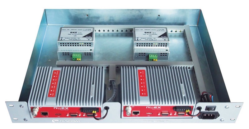
RipEX_D_RACK_230 – 19″ rack shelf double, incl. 2× PS 100–256 VAC /
24 VDC
RipEX_D_RACK_48 – 19″ rack
shelf double, incl. 2× PS 48 VDC / 24 VDC
RipEX_S_RACK_MS – 19″ rack shelf single, incl. MS2000/12 + AKU 7.2
Ah
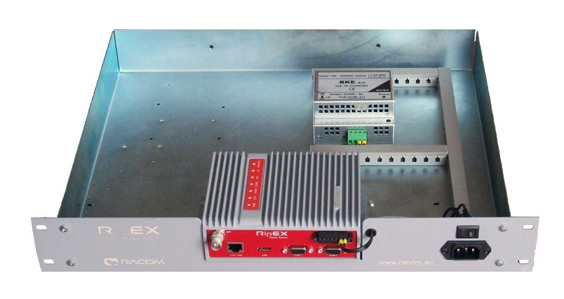
RipEX_S_RACK_230 – 19″ rack shelf
single, incl. PS 100–256 VAC / 24 VDC
RipEX_S_RACK_48 – 19″ rack shelf single, incl. PS 48 VDC / 24
VDC
Others
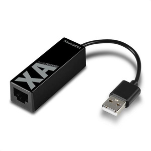
RipEX_X5 – ETH/USB adapter
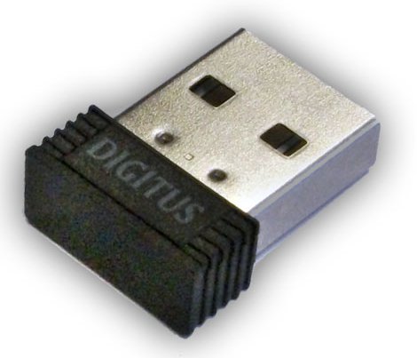
RipEX_W1 – Wifi adapter
RipEX_DEMO_CASE – Demo case (without radio
modems)
RipEX_DUMMYLOAD – Dummy load
antenna
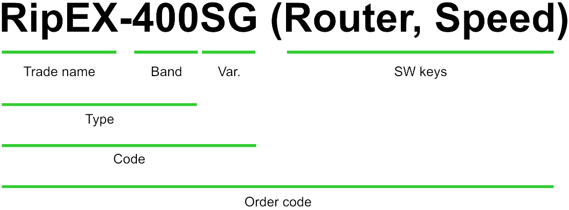
RipEX_C_NM_50 – Feedline
cable, RG58, 50 cm, TNC Male – N Male
OTH-VHF50HN – Coaxial overvoltage protection 100–512 MHz, N female/N
female
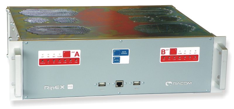
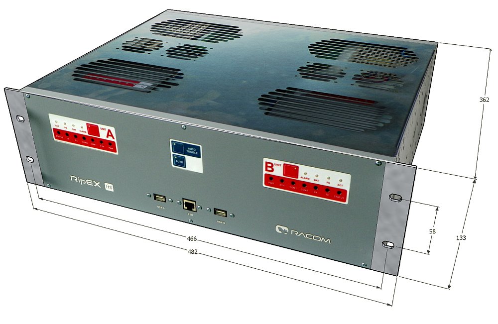
RipEX-HS – 19″ Hot Standby
chassis, RipEX units excl., pow. supplies incl. (has got its own ordering codes,
see RipEX-HS User manual)
RipEX-HSB – 19″ Battery pack chassis for RipEX-HS, batteries
excl.
RipEX-HS is redundant Hot Standby chassis. There are two Hot Standby standard RipEX units inside. In case of a detection of failure, automatic switchover between RipEX units sis performed. RipEX-HS is suitable for Central sites, Repeaters or Important remote sites where no single point of failure is required.
For more information see RipEX-HS datasheet or User manual on www.racom.eu.
ETH/USB adapter for service access to the web interface via USB connector. Includes a built-in DHCP server which provides up to 5 leases. To access the RipEX always use the fixed IP 10.9.8.7. For details on use see Section 4.3, “Connecting RipEX to a programming PC”.
OTH-XA-ETH/USB requires FW 1.7.1.0 or higher. The previous model OTH-X5-ETH/USB is supported in all FW versions.
Wifi adapter for service access to the web interface via USB connector. Includes a built-in DHCP server which provides up to 5 leases. To access the RipEX always use the fixed IP 10.9.8.7. For details on use see Section 4.3, “Connecting RipEX to a programming PC”.
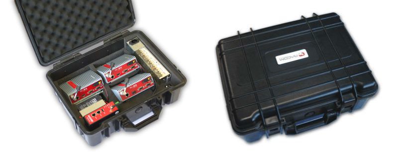
A rugged plastic case for carrying up to three RipEX‘s and one M!DGE 3G SCADA router. It also contains all the accessories needed to perform an on-site signal measurement, complete application bench-test or a functional demonstration of both radiomodems and the 3G router. During a field test, units can be powered from the backup battery and external antenna can be connected to one of the RipEX units through „N“ connector on the case.
Content:
Brackets and cabling for installation of three RipEXes and one M!DGE (units are not part of the delivery)
1× power supply Mean Well AD-155A (100-240 V AC 50-60 Hz/13.8 V DC)
1× Backup battery (12V/5Ah, FASTON.250), e.g. Fiamm 12FGH23
1× Power cable (European Schuko CEE 7/7 to IEC 320 C13)
1× Ethernet patch cable (3 m, UTP CAT 5E, 2× RJ-45)
Quick start guide
RipEX.accessories:
3× Dummy load antennas
1× L-bracket, 1x Flat-bracket samples
1× ETH/USB adapter
1× Wifi adapter
M!DGE accessories:
Stick antenna (900–2100 MHz, 2.2 dBi, vertical)
Mechanical properties of case
Outside dimension: 455×365×185 mm
Weight approx. 4 kg (excluding the RipEX and M!DGE units)
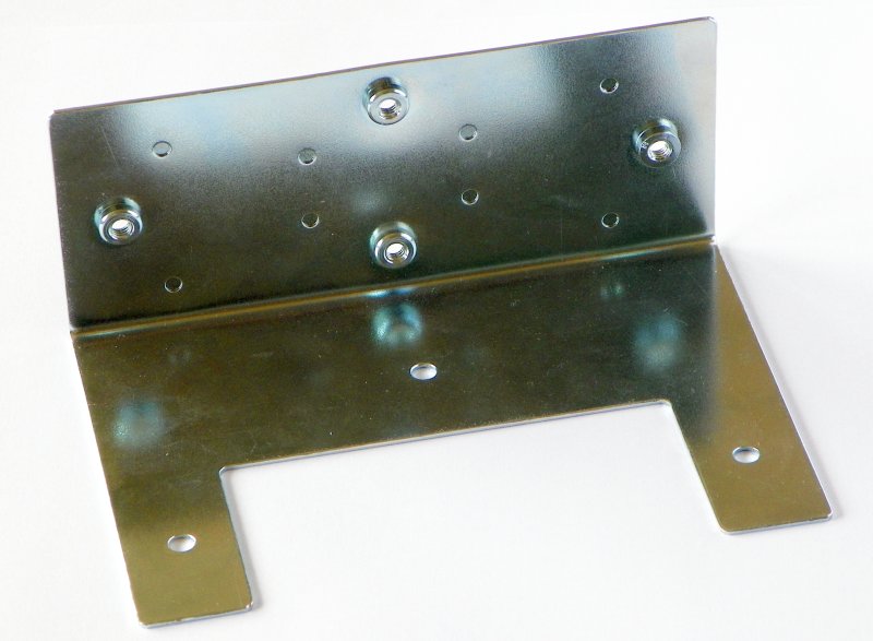
Installation L bracket for vertical mounting. For details on use see chapter Mounting and chapter Dimensions.
Installation bracket for flat mounting. For details on use see chapter Mounting.
1,6U (70 mm) high
Ready for assembly with one RipEX
Weight 2.5 kg (without power supply and RipEX)
Can be assembled with power supply
100 – 256 V AC / 24 V DC
230 V AC / 24 V DC
48 V DC / 24 V DC
MS2000/12 + back up battery 7.2 Ah
19″ rack shelf – double
1,6U (70 mm) high
Ready for assembly with two RipEX’es
Can be assembled with power supplies
100 – 256 V AC / 24 V DC
230 V AC / 24 V DC
48 V DC / 24 V DC
MS2000/12 + back up battery 7.2 Ah
Dummy load antenna for RipEX is used to test the configuration on a desk. It is unsuitable for higher output – use transmitting output of 1.0 W only.
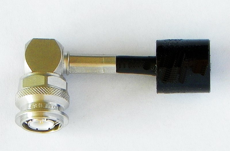
Coaxial overvoltage protection
Frequency range 100-512 MHz,
connectors N(female) / N(female).
Feedline cable is 50 cm long and is made from the RG58 coaxial cable. There are TNC Male (RipEX.side) and N Male connectors on the ends. It is intended for use between RipEX and cabinet panel.
An Automatic antenna switch is mainly used for migrating legacy to RipEX networks. It automatically manages antenna switching: when one base station transmits, the other one is disconnected from the common antenna.
This is an RS232 crossing cable (null-modem) for connection of legacy base station to RipEX. There is also ‘Carrier On’ contact available for legacy base station keying (Relay Dry Contact), managed by CTS envelope from RipEX.
Others
For other accessories (Power supplies, Antennas, Coaxial overvoltage protection etc.) kindly visit https://www.racom.eu/eng/products/radio-modem-ripex.html#accessories