MORSE main menu contains all functions for controlling the CU.
MORSE main menu:

(H)W    (U)nit  (R)adio
(N)odes S(D)R   (B)c
(S)CC   R(F)C   (E)th
(A)rt   r(T)ab  (c)nf
(m)isc  NA(G)

(s)ervice      d(i)ag
(p)ath        (?)help

(o)ld cnf menu

(q)uit
>>
Work with the menu and its options is described in the MORSE Firmware Documentation. The first part of the menu serves for setting configuration parameters, the second for service and diagnostic work and the last allows older versions of software to be controlled. Individual commands are selected by pressing the letter given in brackets. For example, entry of the node address is done as follows:
press
Nfor selection of commandNode, press Enterpress
efor selection of commandedit, press Entermessage ending with
O.K.provides notification that the existing parameters were transferred from the CU to Setrpress Enter to display them
now we can see the state of parameters of menu
Nodes:
  Nodes:
                                 retab
Nid|address |M | u   s | L   N |l w n g H|sTO Err  Cent vTO hTO
(0) 004AE97E     -  S00| -  R00|0 0 0 0| 15 SERV  OFF 304  30
(1) 690F1109    S02 S00| -  R01|1 1 1 1| 15 SERV  OFF 304  30
(2) 00000000    S01 S00| -  R02|0 0 0 0| 15 SERV  OFF 304  30
(3) 00000000    S02 S00| -  R03|0 0 0 0| 15 SERV  OFF 304  30
(4) 00000000    S03 S00| -  R04|0 0 0 0| 15 SERV  OFF 304  30

de(f)ault (r)ead (w)rite
(I)nit (S)ync
(q)uit
>>
We can see that node 1 already has the address 690F1109 inserted and routing tables
local, wide, net and global assigned, each with serial number 1. The
user output from node 690F1109 (row (1), column u)
leads to port SCC2. Other parameters have a recommended initial value,
which is the value that appeared after selecting the command
de(f)ault.
In order to insert for example address 69112233 to
node 4:
press
4 Enter, then follow help on screenpress
a Enterinsert address
69112233 Enter Enterreturn back 1 level
q Enter Enternow the new address which is currently only in Setr can be transferred to S-RAM permanent memory in the CU
w
          Enter
after receiving confirmation of entry
O.K.we can write the new address using commandI Enteralso into RAM memory, thus setting it into operation
The whole operation does not seem very transparent; however after gaining a little experience we can do this from main menu as follows:
Ne  Enter (O.K.) Enter
4a  69112233  Enter Enter
w   Enter (O.K.)
I   Enter (O.K.)
Q   Enter (return to MORSE main menu)
Basic principles of configuration
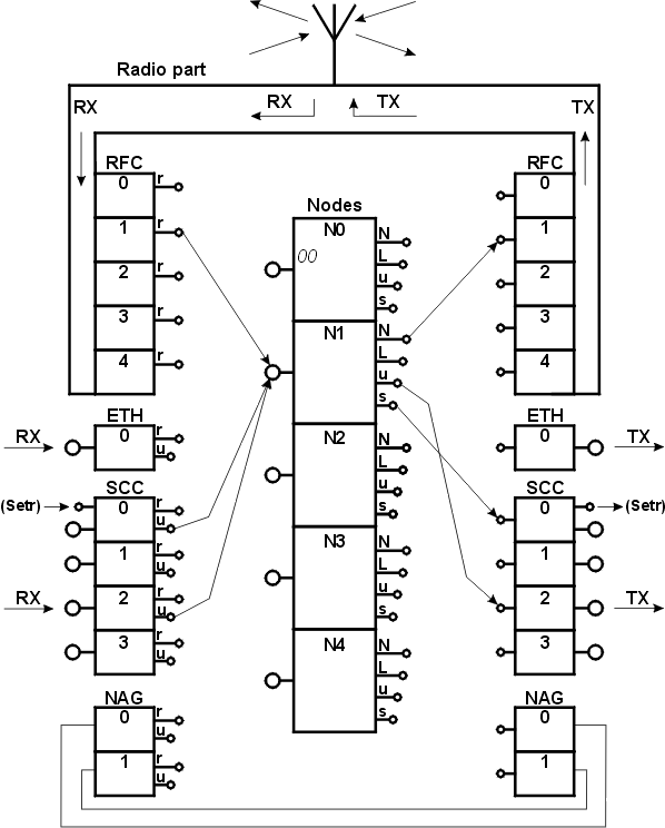
are quite evident from the CU layout diagram:

Connection from the node to the communication channel is set in
the previously mentioned menu Ne, i.e. (N)odes
(e)dit:
  Nodes:
                                 retab
Nid|address |M | u   s | L   N |l w n g H|sTO Err  Cent vTO hTO
(0) 004AE97E     -  S00| -  R00|0 0 0 0 -| 15 SERV  OFF 304  30
(1) 690F1109    S02 S00| -  R01|1 1 1 1 -| 15 SERV  OFF 304  30
(2) 690F1205    S03 S00| -  R02|2 2 0 0 -| 15 SERV  OFF 304  30
(3) 00000000    S02 S00| -  R03|0 0 0 0 -| 15 SERV  OFF 304  30
(4) 00000000    S03 S00| -  R04|0 0 0 0 -| 15 SERV  OFF 304  30
Each node has one row and its columns u,s,L,N define
where the respective output is directed. Row (1) corresponds to
connections in the figure. Another 4 columns l,w,n,g
determine using numbers 1 to 4 which of the prepared routing tables will
be used by the node when resolving routing.
Connection from the SC channel to the node is selected in menu
SIe :
 Channel to Node Interface:
    retranslation     |   user+service             lim
 id N  A t          m | N  A t Base     m  sec brc S   e
(0) 0   NO AR         | 1   NO AR          usr OFF NONE
(1) 0   NO AR         | 2 MASK 00000000/08 usr OFF NONE
(2) 0   NO AR         | 1 MASK 00000000/08 usr OFF NONE
(3) 0   NO AR         | 0 MASK 00000000/08 usr OFF NONE
Again each channel has 1 row; the retranslation group
of columns serves for routing output r and the
user columns are determined for routing output
u. Basic information is carried in column N, which
determines which node the output is routed to. Rows (0) and (2)
correspond to connections in the figure. Other items in the table will
be explained in the SC channel properties definition.
Similarly menu FIe is used for routing outputs from
the radiofrequency channel:
 Channel to Node Interface:
    retranslation     |   user+service             lim
 id N  A t          m | N  A t Base     m  sec brc S   e
(0) 0   NO AR         | 0   NO AR          usr OFF NONE
(1) 1   NO AR         | 0   NO AR          usr OFF NONE
(2) 2   NO AR         | 0   NO AR          usr OFF NONE
(3) 3   NO AR         | 0   NO AR          usr OFF NONE
(4) 4   NO AR         | 0   NO AR          usr OFF NONE
The only difference is in the number of rows, according to the number of RF channels, and in that the user columns are not used here. Row (1) corresponds to connections in the figure. In defining routes from the RF or SC channel to the node the address of this node is simultaneously assigned to the channel. If a packet is then received through a radio part then according to its address it is determined whether is pertains to any of the RF channels. If not then it is not processed any further. If yes then it is transferred to the node along the route configured in this menu.
Menu EIe behaves in the same way for the Ethernet
channel and menu GIe for the Network Agent channels.
For a better understanding of the above-mentioned configuration connections
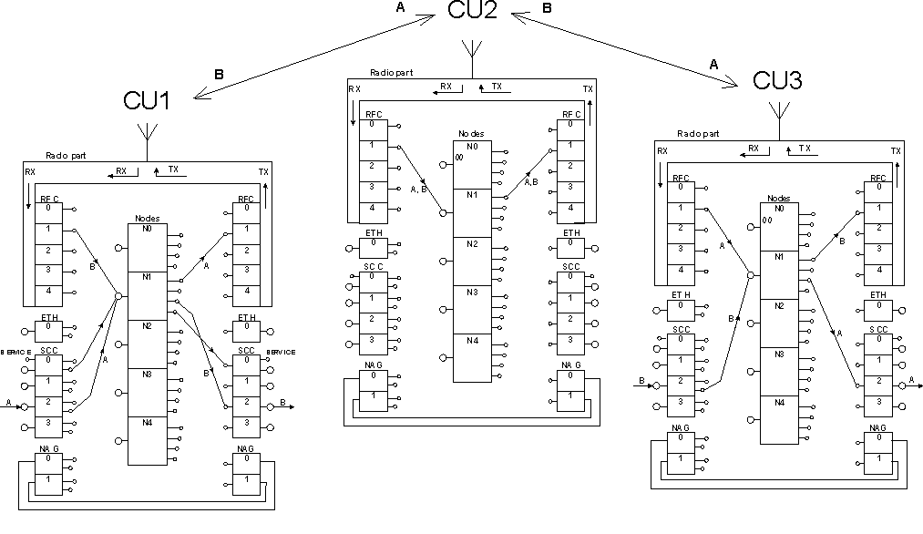
see the figure below of three communication units and connections, forming a simple radio network. Connections used along the packets route are also included:
The packet A is sent from CU1 to CU3:
The packet passes through channel SCC2 (received =RX) to CU1. Node N1 sends it via radio channel RFC1.
Radio part CU2 receives the packet, channel RFC1 sends it to node N1 and from there it continues through the transmitting part RFC1 to the antenna. This step is termed store and forward relaying.
At the destination CU3 the packet is received by the radio part, it is transferred to node N1 by channel RFC1 and from there to the serial channel SCC2, through which the packet leaves the MORSE network (sent through channel SCC2 =TX).
The packet B is sent from CU3 to CU1:
The packets route in the opposite direction from CU3 to CU1 is analogical. It starts with the arrow entering SCC0 in CU3 and ends with the arrow leaving SCC0 in CU1.
Connections connecting SCC0 with node N1 are also drawn. These serve for routing service packets (for example upon configuration setting) between Setr and node 1, because the service cable on MR400 is connected inside CU to SCC0 for this purpose. Similar connections are in each CU, so that access from Setr to each communication unit is possible using the service cable.
As shown in this example the node is the centre of the design-making operations for controlling the route of packets through the network. Introduction to routing gives a definition of these operations.
