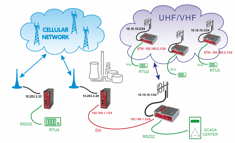
In the example, the SCADA Center is connected via RS232 interface to RipEX1 (COM1). The Center is utilized with Modbus RTU Master configuration and polls two RTUs connected via RipEX network. There is one distant RTU4 location which is reachable over the cellular network.
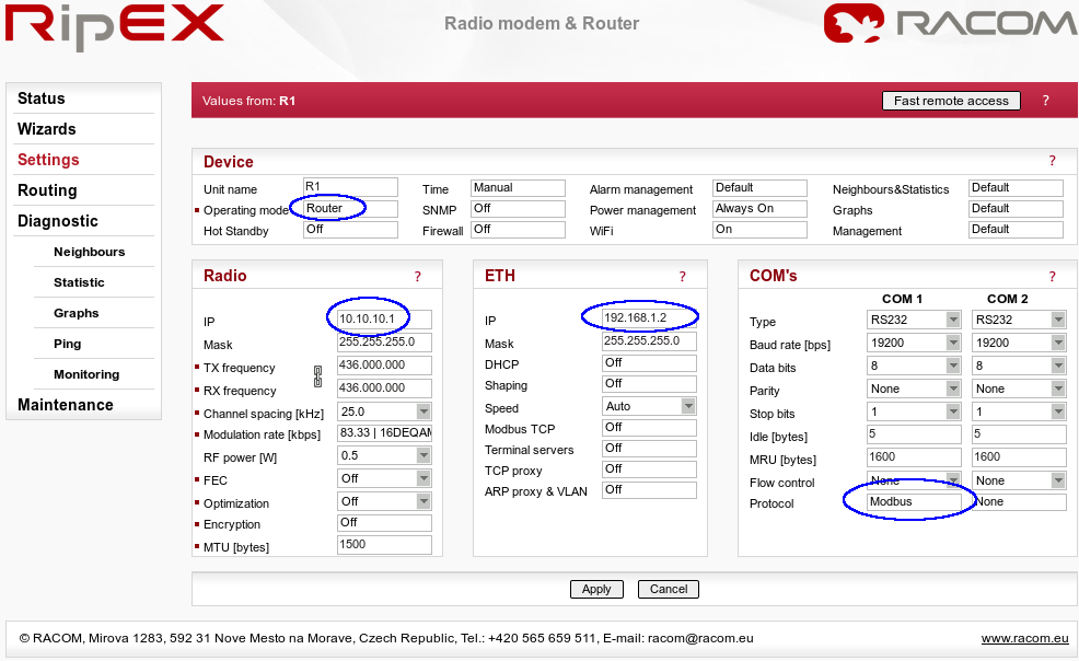
Apply the correct IP addresses within the Router mode and set the COM1 protocol.
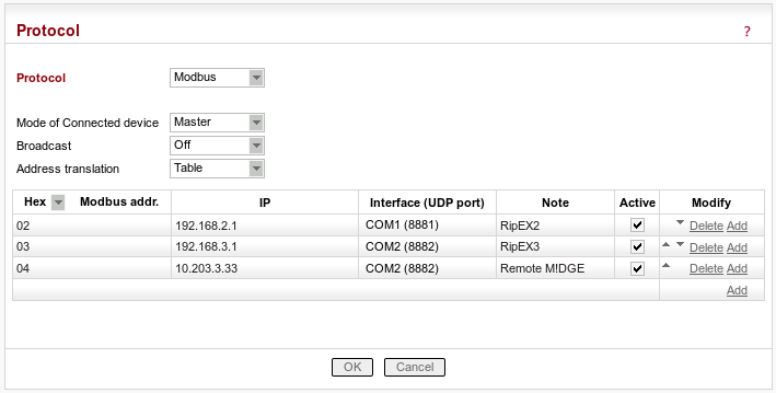
In the example, hexadecimal Modbus addresses 02 and 03 are transferred to the RipEX network on the Ethernet IP addresses. The Slave 04 is transferred via the cellular network and the destination IP address is the mobile IP address of the remote M!DGE unit. The COM port must be COM2 with UDP port 8882, otherwise the remote M!DGE would not handle the traffic correctly.
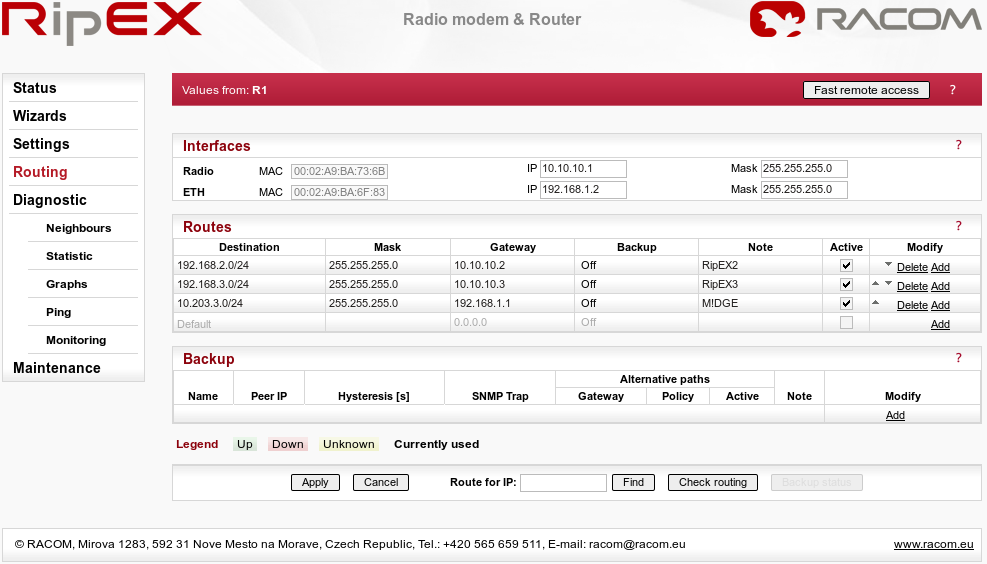
In the Routing menu, three routes have to be added. First two are the LAN subnets of RipEX units and the third line defines the APN subnet (the gateway is the local M!DGE Ethernet IP address).
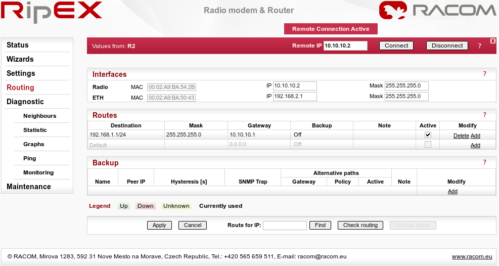
Both remote RipEX units have almost the same configuration so only R2 unit is described. Configure the correct IP addresses (together with RF frequency, …) and set the COM1 port as the Modbus Slave as in the following screenshot.
The only missing configuration is the Routing rule to the central RipEX subnet (192.168.1.1/24).
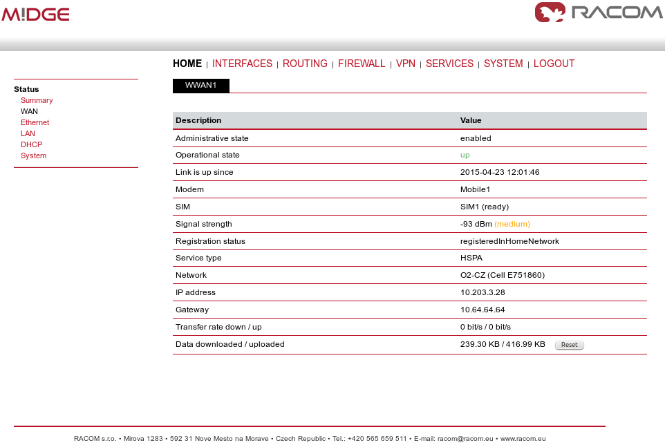
The central M!DGE just needs to be configured so it is connected via the private APN, no other special configuration is needed.
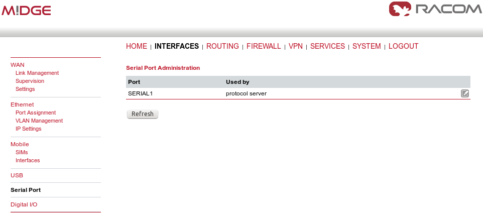
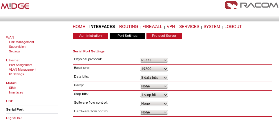
After connecting to the private APN, only the Protocol server needs to be configured. In the INTERFACES – Serial Port, choose the Protocol server.
Set the desired port settings.
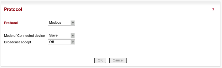
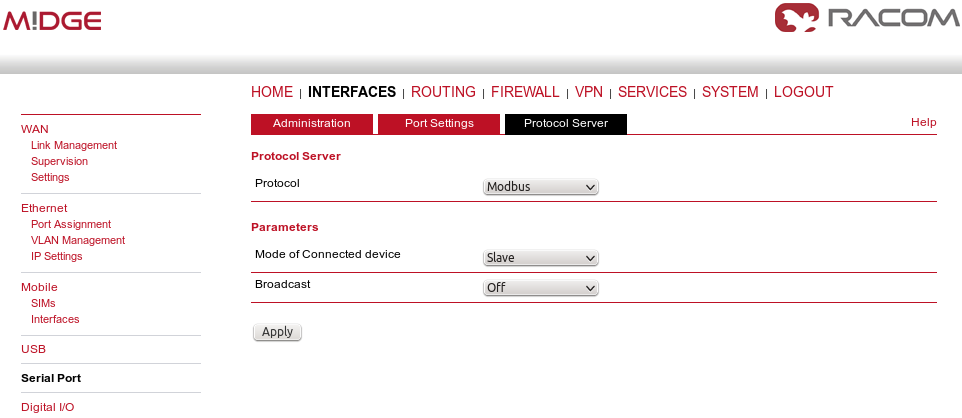
And as the last step, configure the Protocol server as the Modbus slave.
Now you should be able to poll the required information from all RTUs within the UHF/VHF or cellular network.
| Note | |
|---|---|
If you do not use the private APN, you need to configure the VPN tunnels. See VPN Configuration application note and SCADA Protocols public APN. |