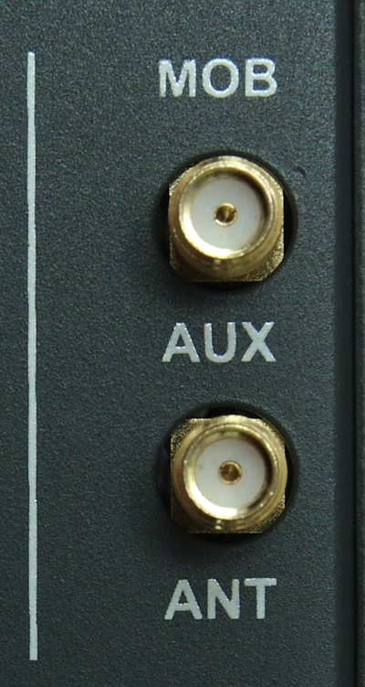
The M!DGE router is equipped with two antenna connectors. The ANT connector serves as a main antenna connection, the AUX connector is auxiliary and serves for better communication with BTS (diversity).
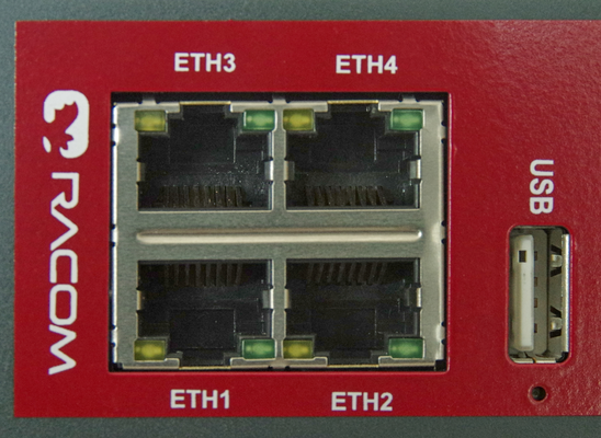
Tab. 4.1: Pin assignment Ethernet interface
| RJ-45 Socket | ETH (Ethernet 10BaseT and 100BaseT) |
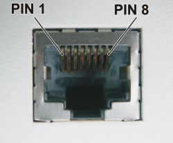 |
| pin | signal | |
| 1 | TX+ | |
| 2 | TX− | |
| 3 | RX+ | |
| 6 | RX− |
| Note | |
|---|---|
Pairs 4-5 and 7-8 have an internal 75 Ohm termination. |
Tab. 4.2: Ethernet Port Specification
| Feature | Specification |
|---|---|
| Speed | 10/100 Mbps |
| Mode | TX− |
| Crossover |
Automatic MDI/MDI-X |
M!DGE uses USB 2.0, Host A interface. USB interface is wired as standard:
Tab. 4.3: USB 2.0 Host Port Specification
| Feature | Specification |
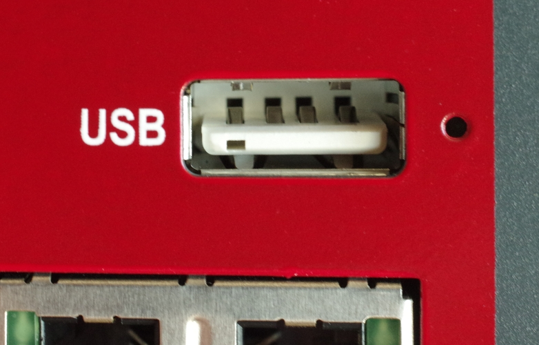 |
| Speed |
Low, Full & Hi-Speed | |
| Current | max. 500 mA | |
| Max. cable length | 3 m | |
| Cable shield | mandatory | |
| Connector type | Type A |
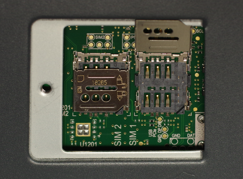
The M!DGE router is equipped with two MicroSIM (3FF) cards slots which are placed under a SIM card cover. Use PH0 screw driver for its opening. If using only one SIM card, use holder one.
The SIM card holder has a locking mechanism – for opening pull the front part of the holder down and then you can open it. After inserting of SIM card (cropped edge left, connectors down), close the holder and lock it.
| Important | |
|---|---|
Power off the router before inserting the SIM card. |
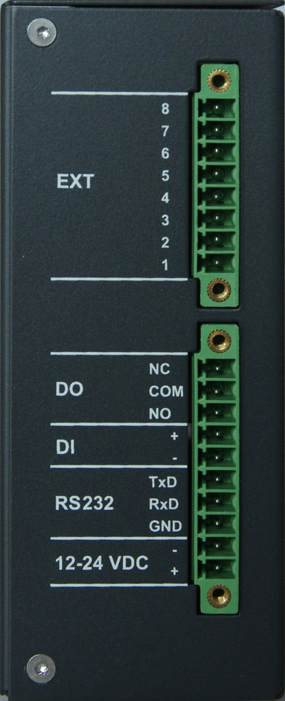
Screw terminal plug types:
Phoenix Contact 1847204 (MC 1.5/10-STF-3.5)
for 10 pins plug and
Phoenix Contact 1847181 (MC 1.5/ 8-STF-3.5) for 8
pins plug (or equivalent).
This EXT plug is delivered only for units
equipped with internal extension module.
Nominal cross section: 1.5
mm²
Tab. 4.5: Screw terminal pin assignment
| pin | pin description | signal |
|---|---|---|
| 1 | 12-24 VDC + | Power input plus: 12–24 VDC (−20% +20 %) = 9.6–28.8 VDC |
| 2 | 12-24 VDC – |
Power input minus – internally connected with casing |
| 3 | RS232 GND | RS-232 GND (non-isolated) |
| 4 | RS232 RxD | RS-232 RxD (non-isolated), received data |
| 5 | RS232 TxD | RS-232 TxD (non-isolated), transmitted data |
| 6 | DI – | Digital input – Negative signal input (isolated to GND) |
| 7 | DI + | Digital input – Positive signal input (isolated to GND) |
| 8 | DO NO | Digital Output isolated, Relay contact normally open |
| 9 | DO COM | Digital Output isolated, Relay common |
| 10 | DO NC | Digital Output isolated, Relay contact normally closed |
Polarity Reversal protection circuit (PTC fuse) used on pin 1 and pin 2, but the reverse polarity with soft power supply could cause damage after a few minutes of wrong polarity attached.
Pins 2 and 3 Pins are internally connected.
RS232: behaves as a DTE device.
Pin 5 voltage -5.4 V (without a
connected device ) from HW version 1.5. In earlier HW versions was 0 V.
Pins 6 and 7 are galvanically isolated (1.5 kVAC). If voltage between the + and – pins is bigger than 60 VDC, the input circuit could be damaged. Reversed polarity will not harm the circuit.
Tab. 4.6: Digital input levels
| logical level 0 | 0 to 3 VDC |
| logical level 1 | 9 to 32 VDC |
| Note: Negative input voltage is not recognised. | |
Tab. 4.7: Digital output parameters
| Maximal continuous current | 1 A |
| Maximal switching voltage | 32 VDC |
| Maximal switching capacity | 32 W |
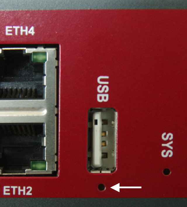
The Reset button is placed close to the USB connector. Use a blunt tool no more than 1 mm in diameter (e.g. a paper clip) to press the button.
The reset button has two functions:
Reboot the system
Press at least 3 seconds to release a system reboot.
The reboot is indicated with the red blinking STAT LED.
Factory reset
Press at least 10 seconds to release a factory reset.
The start of the factory reset is confirmed by all LEDs lighting up GREEN for a second.
Recovery procedure
Press at least 15 seconds to release a recovery procedure.
The start of the recovery procedure is confirmed by all LEDs lighting up RED for a second.
| Note | |
|---|---|
Contact our technical support (support@racom.eu) for recovery procedure details and required files. |
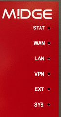
The following table describes the default M!DGE status indicators.
Tab. 4.8: M!DGE interfaces and status indicators
| Description | State | Function |
|---|---|---|
| STAT | green blinking | Device busy device is in startup, software or configuration update |
| green on | Device is ready | |
| WAN | off | Hotlink is disabled |
| blinking | Hotlink connection is being established | |
| on | Hotlink connection is up | |
| LAN | green | ETH: enabled as LAN and link status is up |
| off |
No ETH LAN-connection is up | |
| VPN | green on | VPN connection is up |
| green blinking | VPN connection is being established | |
| off | VPN connection down | |
| EXT | on / off / blinking | EXT LED indicates the state of the extension
interfaces. Hint: Cellular (WWAN) signal strength can be indicated (green = excellent, orange = medium, red = weak). |
| SYS |
Shows the overall system state. This could be derived from health
indicators such as: | |
| green on | System operation state: normal | |
| green blinking | System operation state: warning or in a transition | |
| red on | System operation state: emergency, watchdog, failure |
Tab. 4.9: Technical specifications
| Frequency bands E | 4G LTE Band 20 (800 MHz), Band 5 (850 MHz), Band 8 (900 MHz), Band 3 (1800 MHz), Band 1 (2100 MHz), Band 7 (2600 MHz) |
| 3G UMTS/HSDPA/HSUPA Band 5 (850 MHz), Band 8 (900 MHz), Band 2 (1900 MHz), Band 1 (2100 MHz) | |
| 2G GSM/GPRS/EDGE GSM 850 MHz, E-GSM 900 MHz, DCS 1800 MHz, PCS 1900 MHz | |
| Ublox TOBY-L210 FCC ID XPYTOBYL210 TAC 35225506 | |
| Frequency bands P | 4G LTE Band 28 (750 MHz), Band 5 (850 MHz), Band 8 (900 MHz), Band 3 (1800 MHz), Band 1 (2100 MHz), Band 7 (2600 MHz) |
| 3G UMTS/HSDPA/HSUPA Band 5 (850 MHz), Band 8 (900 MHz), Band 2 (1900 MHz), Band 1 (2100 MHz) | |
| 2G GSM/GPRS/EDGE GSM 850 MHz, E-GSM 900 MHz, DCS 1800 MHz, PCS 1900 MHz | |
| Ublox TOBY-L280 FCC ID XPYTOBYL280 TAC 35850306 | |
| Frequency bands A | 4G LTE Band 17 (700 MHz), Band 5 (850 MHz), Band 4 (1700 MHz), Band 2 (1900 MHz), Band 7 (2600 MHz) |
| 3G UMTS/HSDPA/HSUPA Band 5 (850 MHz), Band 8 (900 MHz), Band 4 (AWS, i.e. 1700 MHz), Band 2 (1900 MHz), Band 1 (2100 MHz) | |
| 2G GSM/GPRS/EDGE GSM 850 MHz, E-GSM 900 MHz, DCS 1800 MHz, PCS 1900 MHz | |
| Ublox TOBY-L200 FCC ID XPYTOBYL200 TAC 35225406 | |
| Frequency bands U | 3G UMTS/HSDPA/HSUPA Band 5 (850 MHz), Band 8 (900 MHz), Band 2 (1900 MHz), Band 1 (2100 MHz) |
| 2G GSM/GPRS/EDGE GSM 850 MHz, E-GSM 900 MHz, DCS 1800 MHz, PCS 1900 MHz | |
| Specification | 4G LTE 3GPP Release 9 Long Term Evolution (LTE) Evolved Uni. Terrestrial Radio Access (E-UTRA) Frequency Division Duplex (FDD) DL Multi-Input Multi-Output (MIMO) 2×2 |
| 3G UMTS/HSDPA/HSUPA 3GPP Release 8 Dual-Cell HS Packet Access (DC-HSPA+) UMTS Terrestrial Radio Access (UTRA) Frequency Division Duplex (FDD) DL Rx diversity | |
| 2G GSM/GPRS/EDGE 3GPP Release 8 Enhanced Data rate GSM Evolution (EDGE) GSM EGPRS Radio Access (GERA) Time Division Multiple Access (TDMA) DL Advanced Rx Performance Phase 1 | |
| Data rates up to 150 Mbps downlink / 50 Mbps uplink |
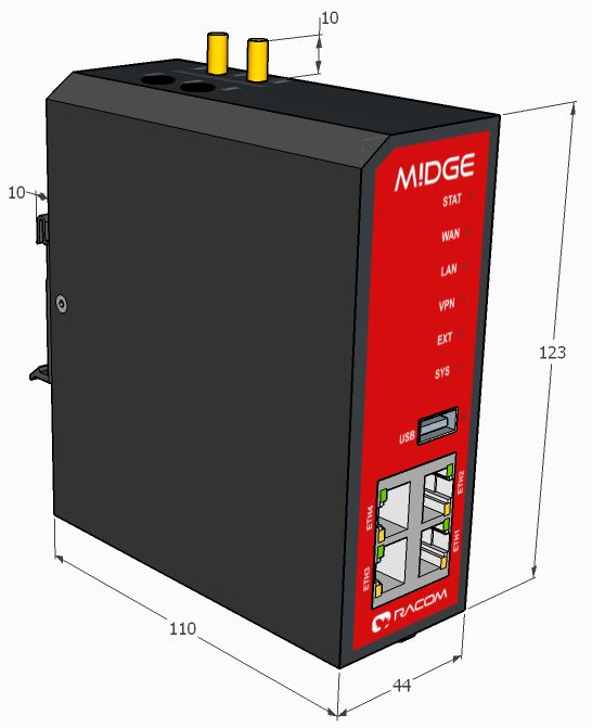
| Mounting | DIN rail mounting |
| Dimensions | 45 W × 110 D × 125 H mm (1.77 × 4.33 × 4.92 in) |
| Weight | Ca. 450 g (0.99 lbs) |
| Type Approval | CE, FCC |
| Feature | Count |
| DHCP reservations | 70 |
| Local host names | 35 |
| NAPT rules | 35 |
| Firewall rules | 50 |
| Firewall address groups | 50 |
| Static routes | 50 |
| Static Multicast routes | 10 |
| Mobile IP | yes |
| Options | |
| Antennas | Various antennas suitable for your application are available |
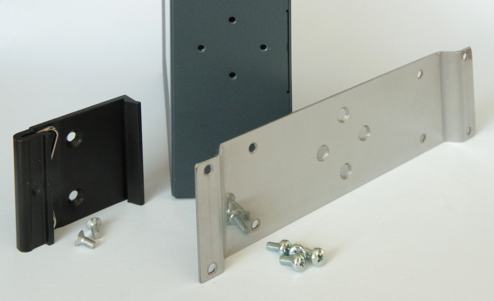
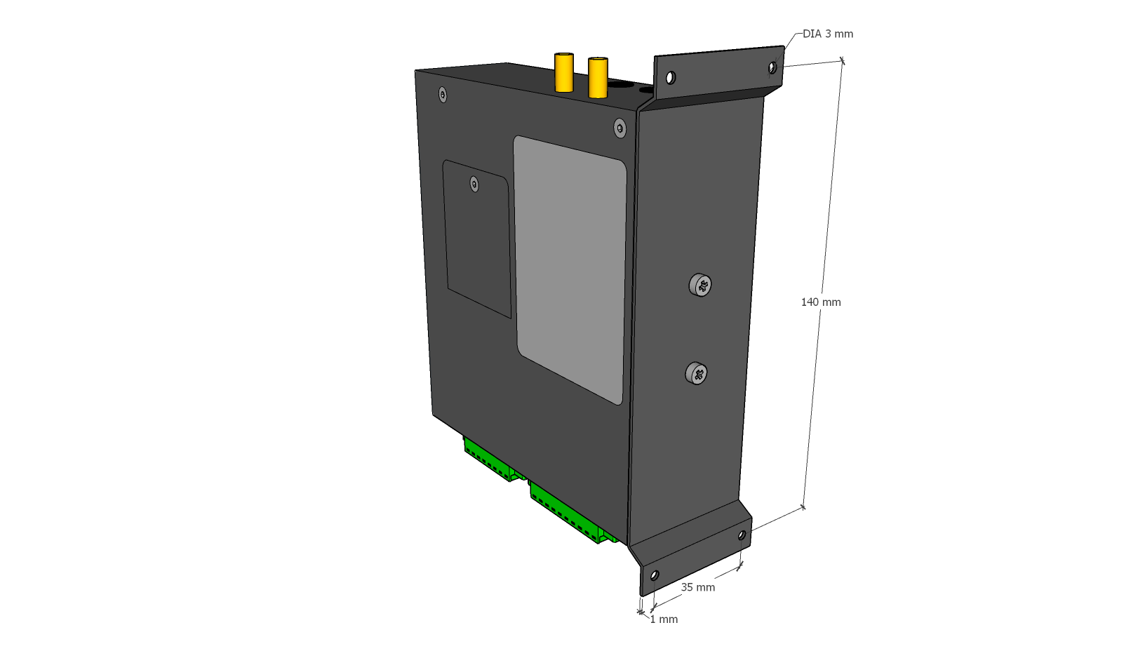
| Mounting kit | Flat bracket mounting kit |
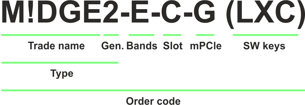
Trade name – trade and marketing name of the product. This name is used for all products within the same product family.
Possible values:M!DGE
Gen. – generation of the product of specific Trade name. The very first generation does not have any number in this position.
Possible values:none
2
Bands – frequency bands
Possible values:E – cellular module, Bands E
NOTE: Frequency bands P, A, U were under production till XII/2022.
Slot – Proprietary extension slot
Possible values:N – not used
C – The second RS232/485 + 1× DI, 1× DO, Part No.: M!DGE2-HW-COM/IO
pin description signal 1 RS-232 GND (non-isolated) 2 RS-232 RxD (non-isolated); RS485 A (Half-Duplex) 3 RS-232 TxD (non-isolated); RS485 B (Half-Duplex) 4 Digital input – Negative signal input (isolated to GND) 5 Digital input – Positive signal input (isolated to GND) 6 Digital Output isolated, Relay contact normally opened 7 Digital Output isolated, Relay common 8 Digital Output isolated, Relay contact normally closed mPCIe – mPCIe slot
Possible values:N – not used
G – GPS (GNSS) module, Part.No.: mPCIe-GPS
NOTE: Frequency bands E, P, A were under production till V/2022.
Bands, Slot, mPCIe positions are used only for M!DGE2.
SW keys – if unit is ordered with SW keys, all keys are specified in this bracket. SW key activates the feature, which is under the license. SW key can be ordered independently for specific S/N anytime later on.
Possible values M!DGE2:LXC – Linux container, Part No.: M!DGE2-SW-LXC
SERVER – Server clients extension, Part No.: M!DGE2-SW-SERVER
Feature Default SW key SERVER OpenVPN clients 10 25
Type – specific product type for which type approvals like CE, FCC etc. are issued.
Possible values:M!DGE
M!DGE2
Order code – the complete product code, which is used on Quotations, Invoices, Delivery notes etc.
In order to find out the correct Order code, please use RACOM WebService.
Flat-bracket
Installation bracket for flat mounting. For usage details see chapter Mounting and chapter Dimensions.