This overview is intended to indicate the links in the Advanced menu and contexts in which they are used. For a more detailed description, see the User manual and the RAy2 helps.
The scheme of frame processing and influence of each submenu is shown in the following diagram.
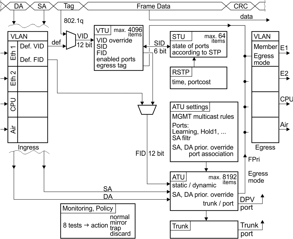
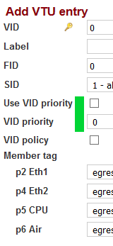
The VLAN ID (VID) is allocated to the incoming frame according to its input port and the tag in the header of the frame.
In the VLAN Table Unit (VTU), a Forwarding Information Database number (FID) is assigned to the framework according to VID. Determining the FID also affects the input port
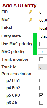
According to FID and Destination address (DA), an output port number is found in the Address Translation Unit table (ATU).
The frame is sent from the switch via this port.
Many other parameters affect this process, as described in the manual and in the built-in help.
Some features in the Advanced menu require setting more than one
parameter. For example, the choice of ports for communication affect
submenus VLAN, STU, VTU, ATU settings and ATU.
In next pages
you can view samples of the first column of each submenu arranged side by
side with the parameters highlighted. Below each menu list is a brief
description of these parameters.
| VLAN | STU | VTU | ATU settings | ATU |
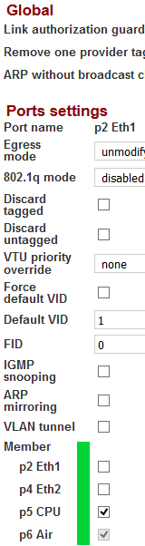 | 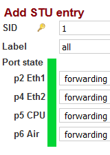 | 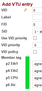 |  |  |
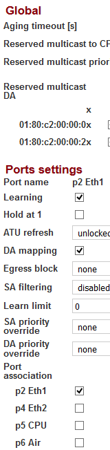
| port IN defines possible output ports | STU defines allowable ports for both input and output | VID defines possible output ports | SA record created in ATU according to Port association | output port assigned by SA record in ATU |
The output port (defined by FID and DA address) for the frame is found in the ATU table. To send the frame via this output port, the conditions set in columns VLAN, STU and VTU must also be met.
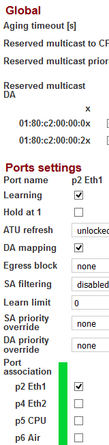
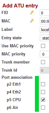
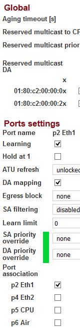
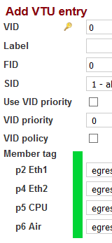
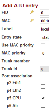
The records in ATU are created according to the “ATU settings / Port association”. The port is usually designated by its own name, eg. p2 -> p2.
| VLAN | STU | VTU | ATU settings | ATU |
 |  |  |  |  |
| 2. port IN defines, which priorities (Pri) will be overwritten according to VID value | 2. VID determines whether overwriting is carried and which value is assigned | 3. the address of the frame defines, which Pri will be overwritten | 3. ATU (address) determines whether overwriting is carried and which value is assigned |
QPri is used when processing frames inside the switch.
FPri is used by the switch to determine the DSCP of an outgoing frame, when either of the parameters “override” has a value “frame”.
Frame priority FPri and Queue priority QPri are determined by the QoS menu.
It is possible to change the priority in the VTU menu according to VID of the framework.
The methods of application change are described in “VLAN / VTU priority override”.Another change can be enabled in the menu ATU for each frame according to its SA or DA.
The methods of application change are described in “ATU settings / SA, DA priority override”.
| VLAN | STU | VTU | ATU settings | ATU |
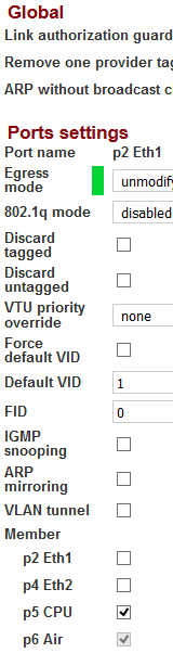 | |  |  |  |
| 2. the output port defines the default tag
setting; it is used, if the VID of the frame is not found in the VTU | 1.the VID (Member tag) determines if and how the frame is given an output tag |
The tag assigned to an output frame based on VID is managed in the
VTU menu.
If a frame’s VID is not found in the VTU table,
the tag assigned to an output frame is determined by the input port
(VLAN menu).