Controls
The following configuration buttons are used for configuration:
| Apply and save parameters. | |
| Set parameters are overwritten with original values. | |
| Reload all current values of the unit / both units. | |
| Show values of individual parameters as they are stored in backup configuration (in the buffer). To use any of these values, you must use the “Apply” button. | |
| Clicking the button displays the values of individual parameters downloaded from the backup file (Backup/Settings/Open file upload). To use any of these values, you must use the “Apply” button. For loading the backup configuration see menu Tools/Maintenance/Backup. | |
| Activating automatic refresh fields marked by | |
| Use the “Stop” button to stop automatic refresh of displayed information with 1sec period. Date and time values are refreshed anyway. |

Help
The microwave link configuration system is equipped with built in Help – see Help section. The Help is accessible in two forms:
Configuration parameter context help. The help text is displayed in the pop up window after clicking the parameter name.
The whole user interface help. The help text is displayed within the configuration screen after clicking the Help menu.
Secure login
You can login into the configuration interface using either the insecure http protocol (default login screen), or the secure https protocol. You should select the connection method on the login screen. If the https protocol is used, it is not possible to tap the network communication and acquire the station’s login information.

Rollback function
If you interrupt the connection on an operating link by entering inappropriate radio link parameters, the original parameters will be restored after 1 minute. The connection is automatically restored.
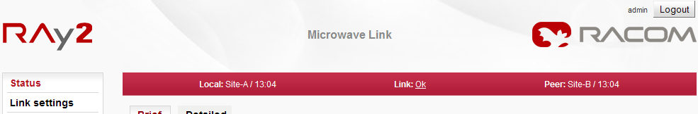
The Status bar is located on the upper part of the screen below the title bar. It consists of 3 fields:
Local unit status (unit assigned to the IP address entered in the browser or CLI)
Local to Peer Link status.
Peer unit status.
Local and Peer field displays:
Station name according to configuration.
Actual time valid for respective unit.
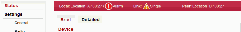
Warning or Alarm icon in case of warning or alarm.
Link field display:
Status of the link between both sides of the microwave link.
Warning icon when the link is not capable of user data transfer.
The Link status can be one of the following values:
| UNKNOWN | Unit start up. The initialization is not yet finished. | |
| SETUP | Unit initialization according to valid configuration. | |
| SINGLE | Unit in operation status. Link to peer unit is not established. | |
| CONNECTING | Connection to peer unit in progress. | |
| AUTHORIZING | Authorization of the peer unit in progress. | |
| OK | Link is connected. Peer unit is authorized. | |
| ANALYZER | Spectrum analyzer mode active. User data are not transferred. |
All link states except for the state of OK are highlighted with a triangle.:
Example of a complete page – status bar, menu and control buttons:
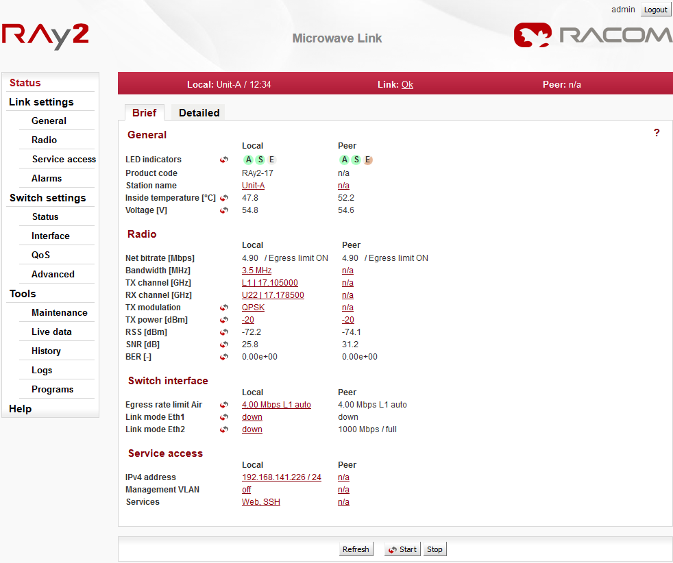
The “Status” menu provides basic information about local and remote station. Informations
is valid the moment the page is open, or the Refresh button is hit.
The
Status/Brief tab shows only the
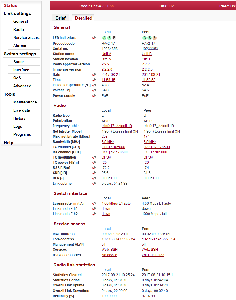
most important values whereas the Status/Detailed
tab provides further details. Below is a list of all values according to
the tab Status/Detailed .
The ![]() icon marks fields which are automatically updated with 30 sec period (or
1 sec when the “Start” button is active).
icon marks fields which are automatically updated with 30 sec period (or
1 sec when the “Start” button is active).
| |||||||||||||||||
| Unit product code – is the same as the Ordering code. | |||||||||||||||||
| Unit serial number. | |||||||||||||||||
| Station name can be modified to reflect the unit location in the network topology. | |||||||||||||||||
| Station location can be used to reflect the network topology hierarchy. | |||||||||||||||||
| Software defined radio version. | |||||||||||||||||
| Unit’s firmware version. | |||||||||||||||||
| The internal real-time clock. The clock is set manually or it is synchronized with NTP server and set for both units. | |||||||||||||||||
| Temperature inside the unit (on the modem board). | |||||||||||||||||
| Unit’s power supply voltage level. | |||||||||||||||||
| The power supply input the unit is powered
from. PoE – unit is powered via Ethernet cable plugged into port “ETH1+POE”. AUX – unit is powered via DC cable plugged into port “P”. | |||||||||||||||||
| Radio unit type: L (Lower) or U (Upper) part of the frequency band. | |
| Horizontal or vertical polarization based on the physical
installation. Indicates the polarization of the received signal.
Local and Peer are indicated separately. The proper position of
the cable is sideways down. Notice for RAy2-17 and RAy2-24 links: One side of the link must be installed in vertical polarization and the other in horizontal polarization. | |
| Displays the currently used frequency table in format <name:version>. | |
| Current transfer capacity of radio channel for user data. | |
| The maximum RF channel capacity according to installed feature key. | |
| One of the standard channel widths can be selected. This parameter must be set identically in local and remote. | |
| Used channels. Both number of the channel and frequency in GHz are listed. | |
| Modulation type currently used for transmitting. When adaptive modulation is enabled, the ACM letters are displayed as well as information about maximum permitted modulation: “current modulation ACM / maximum modulation” | |
| Current output power on the RF channel in dBm. If ATPC is enabled, the ATPC letters are displayed as well as information about maximum permitted power: “current power ATPC / maximum power” | |
| Received signal strength. If ATPC is enabled, the ATPC letters are displayed as well as information about threshold value for activation of power control loop: “current RSS ATPC / threshold RSS” | |
| Signal to Noise Ratio. If ATPC is enabled, the ATPC letters are displayed as well as information about threshold value for activation of power control loop: “current SNR ATPC / threshold SNR” | |
| Bit Error Rate is registered at the receiving end; instantaneous value. | |
| Time elapsed since the current link connection has been established. |
| ||||||||||||||||||||||
| Status of ethernet interface. Current bit rate (10 = 10BASE-T, 100 = 100BASE-TX and 1000 = 1000BASE-T) and state of duplex (FD = full duplex, HD = half duplex). | ||||||||||||||||||||||
| HW address of the Ethernet module. | |
| IP address in the standard dotted decimal notation, including the bit width of netmask after the forward slash. | |
| Service access via VLAN management only. | |
| Services enabled for unit management and monitoring (Web, Telnet, SSH, SNMP, NTP). |
| Information on statistical data: | |
| Time of log clearing. | |
| Period of log refresh. | |
| Radio link statistics: | |
| Overall time the link has been connected. | |
| Overall time the link has been disconnected. | |
| The ratio of “Uptime” and “Downtime”. | |
| Current time the link has been connected. | |
| The longest downtime period recorded. | |
| Length of the last link interruption. | |
| Number of link interruptions. | |
Setup of general parameters of the link.
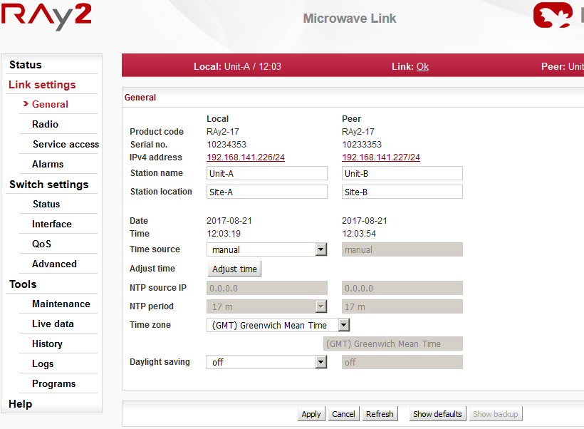
| Unit type indicator. | |
| Unit serial number. | |
| IP address in the standard dotted decimal notation, including the bit width of netmask after the forward slash. | |
| Station name can be modified to reflect the unit location in the network topology. | |
| Station location can be used to reflect the network topology hierarchy. | |
| The internal real-time clock. The clock is set manually or it is synchronized with NTP server and set for both units. | |
| Time synchronization source setup. Manual setup or NTP protocol use. For easier diagnostics of link operation, it is recommended to use the NTP time synchronization. | |
Manual time setup. Use the dialog box to manually set the current date and
time. You can copy time from browser (local PC).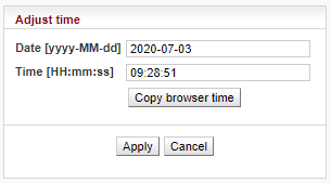 | |
| IP address of the time synchronization server. | |
| Time synchronization interval. | |
| Time zone | |
| Enable daylight saving time |
| Note | |
|---|---|
When the time zone and/or daylight saving time is changed, the original values set in the RAy unit are kept. The actual change takes place after OS restart in order to prevent unexpected states related with local time change. |
Setup of general parameters of the radio link.
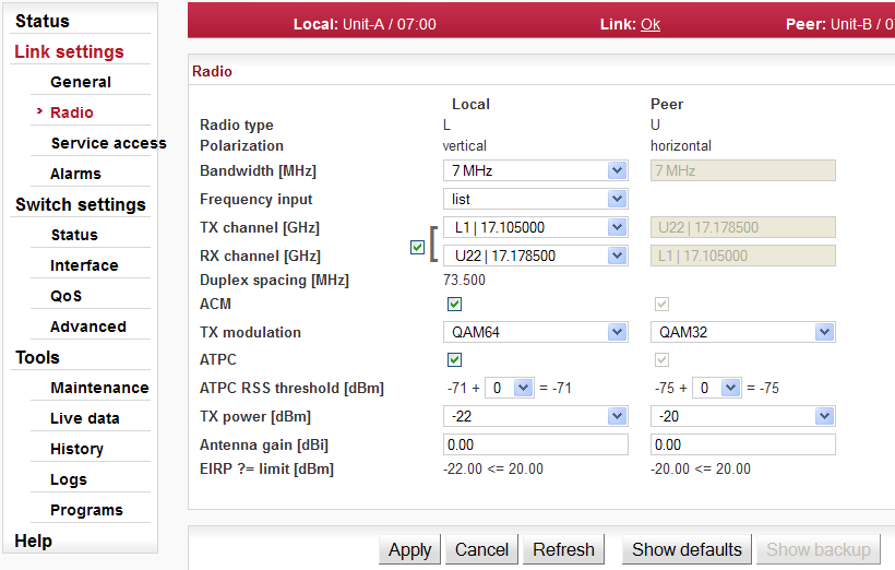
| Radio unit type: L(ower) or U(pper) part of the frequency band. | |
| Horizontal or vertical polarization based on the physical
installation. Indicates the polarization of the received signal.
Local and Peer are indicated separately. The proper position of
the cable is sideways down. Notice for RAy2-17 and RAy2-24 links: One side of the link must be installed in vertical polarization and the other in horizontal polarization. | |
| One of the standard channel widths can be selected. This parameter must be set identically in local and remote. | |
| Enable manual input (if supported). TX and RX frequencies [GHz] are manually entered. It is possible to disconnect the TX-RX lock and select TX and RX channels individually. Corresponding channels at peer unit are set automatically. | |
| TX and RX channels are selected from a list
of channels. The basic configuration has the TX and RX options
interconnected. In this case the basic duplex spacing between
channels is preserved and by selecting one channel, the other
three are defined as well. For units operating in free bands, it
is possible to disconnect the TX-RX lock and select TX and RX
channels individually. Corresponding channels at peer unit are
set automatically. NOTE: Non-standard duplex setting leads to non-effective use of the spectrum. | |
| Information about duplex spacing of TX and RX channel. | |
| Enable automatic control of modulation. | |
| Modulation level for TX channel. You can select in range from QPSK (high sensitivity for difficult conditions) to 256QAM (high speed under appropriate conditions). With ACM enabled the modulation will automatically operate from QPSK to the selected modulation. | |
| Enable automatic control of RF power (see Note below for more details). Its
maximum is defined by parameter ‘TX power’ below. Power is regulated towards lower level while maintaining signal level high enough not to affect current degree of modulation. | |
| The ATPC algorithm controls the output power according to RSS of the peer unit. The lowest allowed RSS (the threshold) is approx. 10 dBm above declared sensitivity for BER 10-6. If necessary, it is possible to use this parameter to move the threshold slightly up or down. | |
| RF output power. With ATPC enabled this parameter defines maximum RF power level. | |
| Gain of used antenna. It is used to calculate approximate
EIRP. Valid only for RAy2-17 and RAy2-24 links. | |
| Approximate calculation of EIRP. Number on the right
shows the allowed EIRP limit. Sign between numbers gives
information on compliance / noncompliance with allowed EIRP
limits. If the EIRP limit field background
is RED, the value shown may be used but will exceed the EIRP
limit. This field value will only be shown for certain RAy2-17 and RAy2-24 links and based on the Frequency tables used. |
| Note | |
|---|---|
The principle behind ATPC is to maintain the lowest transmitting power
without affecting the throughput of the link. The output is primarily controlled by RSS on
the opposite side. ATPC is also used to maintain SNR thus protecting the selected
modulation level. The principle behind ACM is to maintain the connection between the two
units even when degraded propagation conditions are experienced which make it impossible
to maintain the selected modulation level. ACM regulates modulation across all ranges from
QPSK to TX modulation according to the limits in table ACM
switching according to SNR state. In normal operating conditions, ATPC is applied first (even if it is the slower control loop). When deterioration in propagation conditions gradually increases the attenuation on the route, it is compensated by increasing RF power. ACM control will only be applied in conditions when ATPC reaches its ceiling. |
Access routes for link configuration.
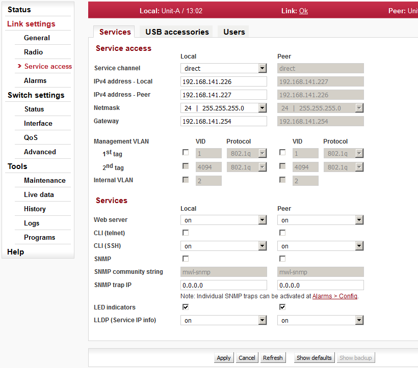
| There are two modes of accessing the internal management system of the microwave link: standard and direct | |||||||||||||
| |||||||||||||
| |||||||||||||
Service IP address, by default 192.168.169.169 for L unit and 192.168.169.170
for U unit. Four addresses 169.254.173.236/30 are used for internal communication.
Must not be used as service IP address. Those four addresses are not used while
“Service channel” is set to “direct” mode.
| |||||||||||||
| Management address of the Peer station. This address has to be set up when the “Service channel” is set to “direct” mode. | |||||||||||||
| Mask for service access, 24 by default. | |||||||||||||
| Default gateway for service access; empty by default. | |||||||||||||
| Enables access via VLAN management. Blocks access for
https, ssh and telnet configuration via untagged packets
(without VLAN) making only VLAN access possible. VLAN
management is off by default. WARNING: By enabling VLAN management, ALL accesses are blocked for configuration using normal (untagged) LAN! During tests, you may enable VLAN management on one unit only (if the “Service channel = standard”). Then it is possible to access the link via LAN and VLAN either directly or via radio link. | |||||||||||||
| VLAN management ID, by default 1. This field must have a value entered even when VLAN management is not active. | |||||||||||||
| Protocol 802.1q or 802.1ad | |||||||||||||
| Valid only for “Service channel = standard”: The RAy
uses one VLAN id for internal service communication between
both units. There are two situations when it might be necessary to change the Internal VLAN id: – Conflict within user data flow when the same VLAN id is already present within a data flow. – Conflict with the internal management address of another RAy unit located at the same site and connected in the same LAN segment. NOTE: The Ethernet frames within this service channel are marked with IEEE 802.1p priority class “7”. Default parameters for QoS and Egress queue control are pre-set to prioritize this service communication channel. | |||||||||||||
| Allows access via web server (for HTTP and HTTPS
protocol). WARNING: after disabling access via web server, you will not be able to access the unit using a web browser! | |||||||||||||
| Enables access via telnet protocol. Provides access to CLI (Command Line Interface) for simple telnet clients. Disabled by default. | |||||||||||||
| Enables access via SSH protocol. Provides secure access to CLI. If preventing unauthorized access to the unit is the number one priority, leave only this server on. | |||||||||||||
| Enabling SNMP server. Off by default. | |||||||||||||
| SNMP community string. Can contain both lower and uppercase letters, numbers, four characters . : _ – and can be up to 256 characters long. | |||||||||||||
| Address for sending SNMP traps. It is possible to record up to 3 addresses separated by commas. | |||||||||||||
| Enable LED status indicators on the body of the unit. You can turn off all LEDs with this option. | |||||||||||||
| |||||||||||||
The USB connector is used for management access (not for user data) to the local unit using Ethernet or WiFi adapter. Only RACOM recommended adapters are supported.
Default WiFi IP address of the unit is 172.17.17.17 with DHCP enabled by default allocating IP address automatically to connected device.
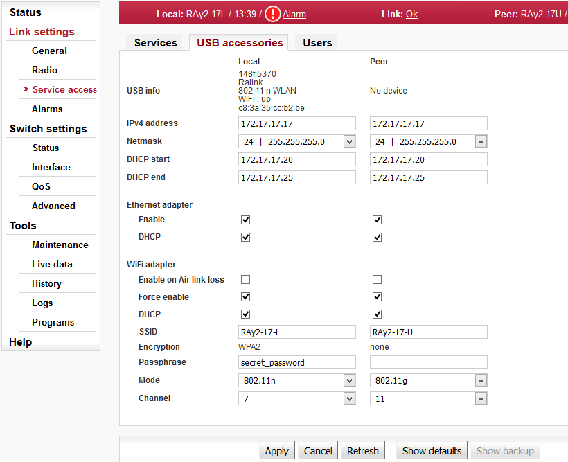
| Status information about device connected via the
USB: n/a – info not available (peer has older fw), or No device – no device plugged in the USB port, or Vendor ID:Product ID Manufacturer Product WiFi/Eth: up/down … only for network device MAC … only for network device | |
| Unit service management address when connecting via USB port. | |
| Network mask when connecting via USB port. | |
| DHCP range for dynamic address allocation of the management client connected via USB port. | |
| USB to Ethernet adapter operation Enable/Disable. | |
| DHCP server for the client(s) connected via USB to Ethernet adapter. | |
| USB to WiFi adapter is only activated during Air-Link loss – means WiFi starts to work and transmit SSID. WiFi is activated 60 seconds after Air-Link loss and deactivated 600 seconds after the Air-Link is restored. The WiFi passphrase should be set by admin before using this option (if not WiFi management alarm is activated). | |
| USB to WiFi adapter is forced to be permanently active
(and to transmit SSID) and WiFi management alarm is
activated. WiFi passphrase should be set by admin before using
this option. This parameter has a higher priority than “WiFi adapter enable on Air link loss”, so if it is set ON then WiFi activity does not depend on Air-Link status. | |
| DHCP server for the client(s) connected via the USB to WiFi adapter. | |
| Service WiFi SSID can be max 32 characters long. | |
| Service WiFi encryption is WPA2 and can not be changed. Factory default is “none” due to missing passphrase. WPA2 is applied automatically once any passphrase is entered. | |
| Service WiFi passphrase has to be 8-64 characters long. The WiFi passphrase should be set by admin before any use of WiFi. Until passphrase is set, WiFi management alarm is activated. | |
| Service WiFi mode can be IEEE 802.11n or IEEE 802.11g | |
| WiFi channel can be set 1-11 depending on WiFi mode
setting (see parameter above): IEEE 802.11n – channels 1-7 IEEE 802.11g – channels 1-11 The WiFi adapter does not search for conflicts in the air. If problems occur, changing the channel is the easiest way to resolve the issue. |
| Note | |
|---|---|
When upgrading from FW older than 2.1.28.0 it is necessary to click “Show Defaults” followed by “Apply” to enable smooth WiFi functionality. |
List and setup of users. Example menu of the
cli_super level user.
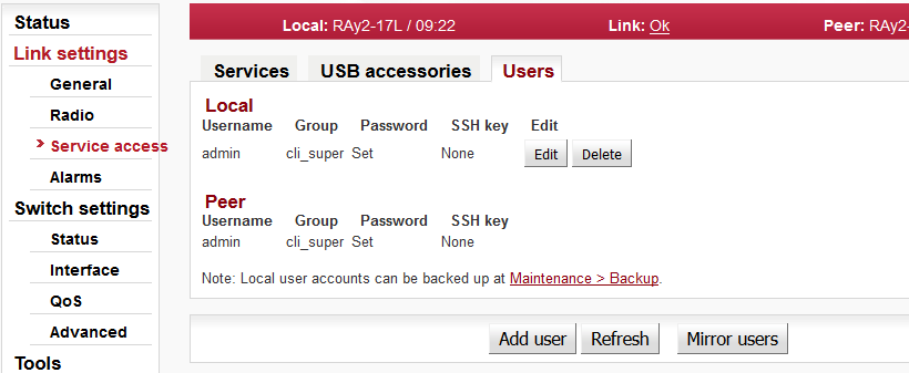
Within the default Factory Settings one user is defined in the
system. This user has username admin
and password admin and is assigned
the highest level of permissions cli_super. This user
then assigns other users to the system along with their level of
permissions.
Service access has three groups of users with different levels of permissions.
| Permissions | cli_guest | cli_admin | cli_super |
| Create new user | No | No | Yes |
| Change own password | Yes | Yes | Yes |
| Delete user * | No | No | Yes |
| Copy (Mirror) permissions local to peer | No | No | Yes |
| Configure and modify link settings | No | Yes | Yes |
Numbers of users that can be defined in the system:
| Group | No of users |
| cli_guest | 10 |
| cli_admin | 10 |
| cli_super * | 2 |
* The system prevents the
user from deleting both cli_super accounts.
The logged on user is shown in the top right of the screen. There can be different users on either end of the link.
| Important | |
|---|---|
It is strongly recommended that the default password admin is changed. Similarly all other users should change their password. Using the CLI, it is appropriate to supplement the SSH key. |
| List of users on Local and Peer stations. |
| This name is entered at Login to log into the link management. | |||||||||||||
| |||||||||||||
| Information about whether user has a password | |||||||||||||
| Information about whether user has at least one ssh key defined. | |||||||||||||
| Note | |
|---|---|
More users concurrently If two or more users work concurrently on the unit any change of configuration settings should be applied by all users. This applies to the menu Link settings which works with both, Local and Peer parameters. Notification to other users: If one user sends the Apply command, other users will receive a message: “Configuration changed, please go to Link settings and click Refresh”. Other users can only use the Apply command after refreshing Link Settings. |
Edit use
Clicking “Edit” next to a username opens a screen with configuration of the given account.

| User name | ||
| The group to which this user will belong. | ||
| Password can be set or deleted. Delete – User will not have a password. The user will only be able to log in with an ssh key. In order to delete the password, you must first upload the ssh key. Set – Password settings. | ||
| New password. | ||
| Repeat password. | ||
| Working with ssh key. Delete – Clear all ssh keys from user account. Set/replace – Add a new key. If there already was any key(s), it will be overwritten. Add – Add a new key. You can enter multiple ssh keys in this way. | ||
| Insert key file. | ||
|
Save the menu content by clicking on the button Apply. | ||
Backup user
| The user settings can be backed up, see Tools / Maintenance / Backup. |
Delete user
Users at level cli_super have a Delete
button next to each user. Delete a user using this button
without being asked to confirm deletion. Users at level
cli_super cannot both be deleted. |
Add user
| The button is located on the bottom bar. | |
For level cli_super users, the “Add user”
button is active. Use it to create a new user within any
group. |
| Name of new user. | ||
| The group to which this user is assigned. | ||
| Password for this user. | ||
| Repeat password. | ||
| If you want the user to have access using ssh protocol and identity verification using ssh key, enter the ssh key here. | ||
| Create a new user account by clicking on the button Apply. | ||
Mirror users
| The button is located on the bottom bar. | |
For level cli_super users, the “Mirror
users” button is active. This function will copy all user
accounts from Local unit to Peer unit. All existing user
accounts on the Peer unit are deleted. |
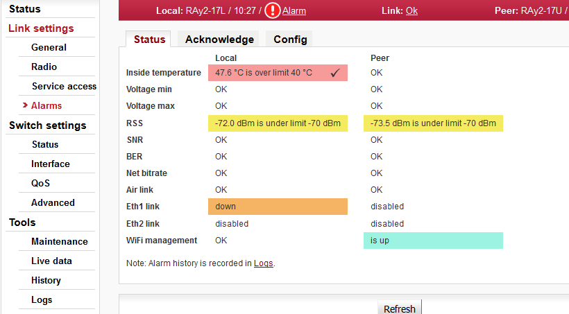
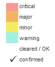
Overview of alarms
All system alarms are listed on this screen. Inactive alarms are colored white with an “OK” text label. Active alarms are colored according to the severity of the alarm with a text message describing the measured value status.
For a detailed description of each Alarm click on the Alarm name.
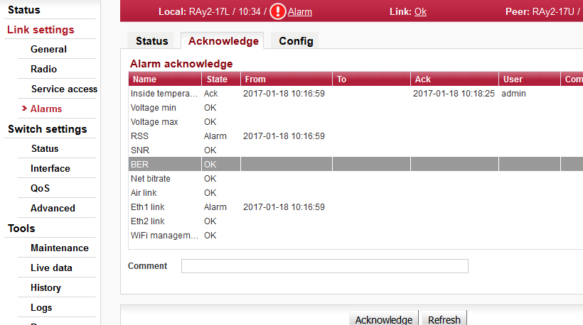
Alarm acknowledgement allows the operator to confirm the system is set in alarm state. Only an active alarm can be acknowledged. Multiple selections of active alarms (to acknowledge groups of alarms) can be performed using Shift or Ctrl keys.
| Alarm identification – The following alarms can appear:
Inside temperature, Voltage min, Voltage max, RSS, SNR, BER, Net bitrate, Air link, Eth1 link, Eth2 link, RF power, WiFi management | |
| There are three possible alarm states: OK … No alarm (alarm is inactive) or alarm disabled. Ack … Alarm is active and acknowledged. Alarm … Alarm is active and is not acknowledged. | |
| Time stamp when the alarm occurred. | |
| Time stamp when the alarm expired (returned to normal conditions). | |
| Time stamp when the alarm was acknowledged. Time stamp format: yyyy-MM-dd hh:mm:ss | |
| Name (login) of the user who acknowledged the alarm. | |
| The comment field can be used to add user defined
comments when an ‘alarm acknowledge’ is performed. Use this
comment field to describe important details of the alarm
status. The comment can be up to 50 characters long. Special
characters are not allowed. The alarm can be acknowledged multiple times with different comments. Every acknowledgement is written to the internal memory and is visible in the alarm log. |
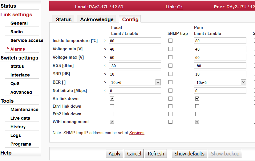
The diagnostics system of the link monitors the operation of the unit.
It generates various event outputs – system warnings and alarms. The event is always written to the system log and indicated in the status bar and Alarms/Status screen. Some events have adjustable thresholds. Events with no adjustable thresholds may or may not be Enabled. If they are not Enabled, the system event is not activated even if the system status is changed.
If the event goes above or below the set parameter limits or a link goes down or up, you can choose to send an SNMP trap. All SNMP traps are OFF in defaults.
| alarm | default | description |
| Temperature inside the unit (on the modem board). Active if temperature exceeds the threshold. | ||
| Lower threshold of supply voltage. Active if voltage drops below min voltage
threshold. The same SNMP trap (same OID) applies for both Voltage min and max. | ||
| Upper threshold of supply voltage. Active if voltage rises above max voltage
threshold. The same SNMP trap (same OID) applies for both Voltage min and max. | ||
| Received Signal Strength. Active if RSS drops below RSS threshold. | ||
| Signal to Noise Ratio. Active if SNR drops below SNR threshold. | ||
| >10e−6 | Bit Error Rate is registered at the receiving end – instantaneous value. Active if BER exceeds the threshold set in this parameter. | |
| The system warning is generated when the current transfer capacity of radio channel is lower than the threshold set in this parameter. | ||
| Interruption of radio link. Active if radio link is interrupted and units can not communicate by Air. | ||
| Corresponding user Eth link (Eth1/Eth2) on station interrupted.
NOTE: The “EthX link” system alarm can only be activated if this alarm is Enabled. When the alarm is not Enabled, the “EthX link” alarm on Status screen is always “Ok” regardless of the current status of the Ethernet link. | ||
| Loss of transmit power (not applicable for RAy2-17 neither RAy2-24). | ||
| Warning is generated when WiFi passphrase is not set or WiFi adapter (and Host Access Point) is permanently enabled (WiFi Force Enable is ON). Parameter can not be changed in web interface (only through CLI). |
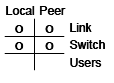
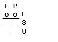
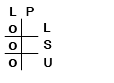
The unit internal Ethernet switch port status
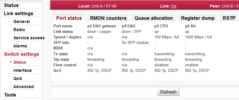
| |||||||||||||||||||||||||||||||
| |||||||||||||||||||||||||||||||
| |||||||||||||||||||||||||||||||
| |||||||||||||||||||||||||||||||
| Status of the internal crossover of Ethernet cables. (MDIX = internally crossed pairs, MDI = direct connection, N/A means an unknown state). | |||||||||||||||||||||||||||||||
| |||||||||||||||||||||||||||||||
| |||||||||||||||||||||||||||||||
| |||||||||||||||||||||||||||||||
The unit internal Ethernet switch RMON counters

The Remote Network MONitoring (RMON) MIB was developed by the IETF to support monitoring and protocol analysis of LANs.
| |||||||
The Internal switch port RMON counters
These counters provide a set of Ethernet statistics for frames received on ingress and transmitted on egress.
| |||||||||||||||||||||||||||||||||||||||||||
| |||||||||||||||||||||||||||||||||||||||||||
| |||||||||||||||||||||||||||||||||||||||||||
| |||||||||||||||||||||||||||||||||||||||||||
| |||||||||||||||||||||||||||||||||||||||||||
| |||||||||||||||||||||||||||||||||||||||||||
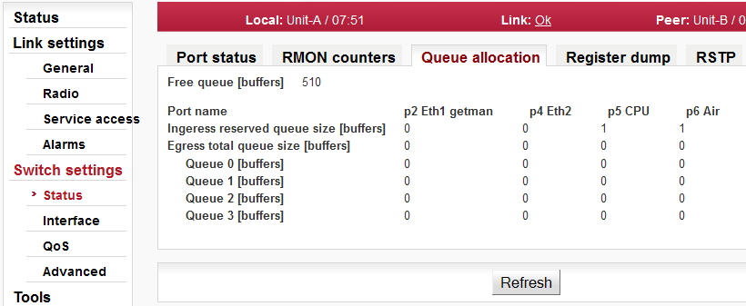
| |||||||
| |||||||
| This counter reflects the current number of reserved Ingress buffers assigned to this port [buffers]. | |||||||
| This counter reflects the current number of Egress buffers switched to this port. This is the total number of buffers across all priority queues [buffers]. | |||||||
| Those counters reflect the current number of Egress buffers switched to this port for individual priority queues [buffer]. | |||||||
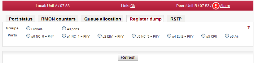
The exact contents of the internal switch configuration and diagnostic registers can be listed for diagnostic purposes. All registers are separated into several groups.
| |||||||
| Port specific parameters. | |||||||
| Registers contents is listed in hexadecimal notation. |
Port settings
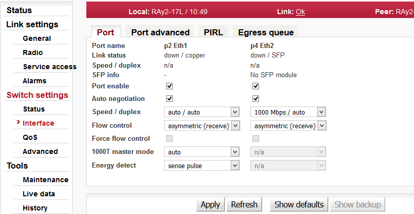
Phyter is responsible for Ethernet signal conversion between wire (e.g. CAT7 cable) and internal switch bus.
The unit internal Ethernet switch Port settings
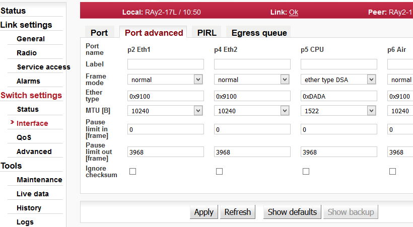
| |||||||||||||||||||||||||||||||||
| Custom port name. | |||||||||||||||||||||||||||||||||
| |||||||||||||||||||||||||||||||||
| |||||||||||||||||||||||||||||||||
| |||||||||||||||||||||||||||||||||
| |||||||||||||||||||||||||||||||||
| |||||||||||||||||||||||||||||||||
| |||||||||||||||||||||||||||||||||
PIRL (Port based Ingress Rate Limiting) has the task of arranging the transfer of frames; ensuring as few frames as possible are discarded and that ports are not blocked.
Diagram of framework processing options are available within the QoS, PIRL and Egress queue control menus:
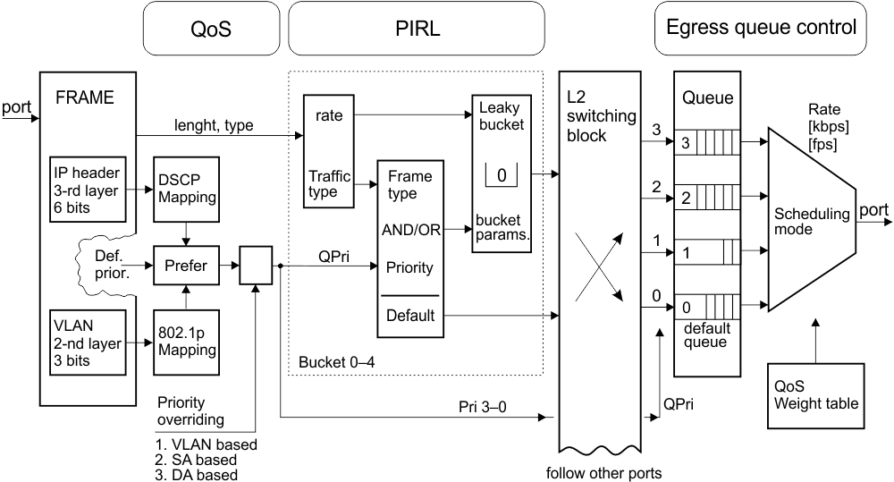
Frame
The frame comes via port, has a certain length and MAC addresses SA and DA. The IP header carries the DSCP priority and may also carry the 802.1p VLAN priority.
QoS
The Queue priority (QPri) is created based on preferences within the DSCP or 802.1p priority. This priority takes values from 0 to 3, and controls the processing of frames inside the switch.
Untagged frames are provided with 802.1p priority by default.
Priorities may be remapped.
The priority can also be overwritten by the Advanced menu priority derived from a VLAN, SA and/or DA addresses.
The Frame priority (FPri) is processed in a similar manner. Frame coming from the network and frame being sent to the network is marked by this priority.
PIRL
Between the port and the common switch there may be between 1 and 5 “flow restrictors” working in parallel according to the schedule “leaky bucket”. These are called “Resource”. This is analogous to the container which is intermittently replenished by tokens according to incoming frames and is continuously emptied. Regulatory measures are implemented at a certain height to ensure the bucket does not overflow.
PIRL – Edit section of this menu is made up of several groups of parameters:
Resource identification.
Resource capacity, transfer byte into tokens.
Method of counting frames.
Regulatory interventions (drop frame – reduce feeding)
Selecting frames (all – by priority QPri – by type).
The above mentioned parameters are used to allocate part of a frame to each Resource. Their passage is regulated thus avoiding network congestion. If there is a framework that does not match the filter of any Resource, this then passes to the switch without restrictions.
Switching block
In this block (L2-switch) each frame is routed to a designated port according to the Advanced menu.
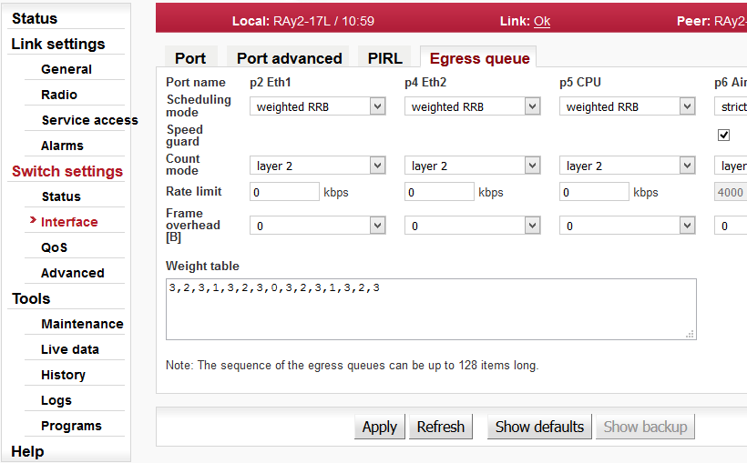
Egress queue
Block output queues. Each port receives frames from the L2 switch through 4 queues (No. 3-0). The highest priority has a queue No. 3. The frames are organized into queues according to their priorities QPri.
The Method to empty queues is selected by the parameter Scheduling Mode. The emptying rate is governed by the Rate limit parameter.
A Frame sent from the port to the network can be identified by
priority FPri, although it is also possible to change its tag: see
menu VLAN/Egress mode.
Port based ingress rate limiting, see also the Functional diagram
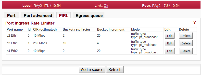
The device supports per port TCP/IP ingress rate limiting along with independent Storm prevention. Port based ingress rate limiting accommodates information rates from 64 Kbps to 1 Mbps in increments of 64 Kbps, from 1 Mbps to 100 Mbps in increments of 1 Mbps and from 100 Mbps to 1000 Mbps in increments of 10 Mbps.
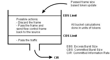
In addition to this, the device supports Priority based ingress rate limiting. A given ingress rate resource can be configured to track any of the four priority traffic types. One of the popular schemes for implementing rate limiting is a leaky bucket. The way a leaky bucket scheme works is that the bucket drains tokens constantly at a rate called Committed Information Rate (CIR) and the bucket gets replenished with tokens whenever a frame is allowed to go through the bucket. All calculations for this bucket are done in tokens. Therefore, both bucket decrementing and incrementing is performed using tokens (i.e., frame bytes are converted into bucket tokens for calculation purposes).
The device supports a color blind leaky bucket scheme.
The traffic below Committed Burst Size limit (CBS Limit) is passed without any further actions. If the traffic burst were to continue and the bucket token depth approaches closer to the Excess Burst Size limit (EBS Limit) by less than the CBS Limit, then a set of actions are specified. Note that if the frame gets discarded then the equivalent number of tokens for that frame will not get added to the bucket.
There are the two default ingress limiting rules already configured in the switch default configuration. They limit the maximum allowed ARP traffic coming to the CPU port to 10Mbps from Eth1 and 10Mbps from Eth2 ports.
| |||||
| Ports Eth1, Eth2, CPU, Air. See Port status. | |||||
| |||||
| |||||
| |||||
| |||||
| |||||
| |||||
| |||||
|
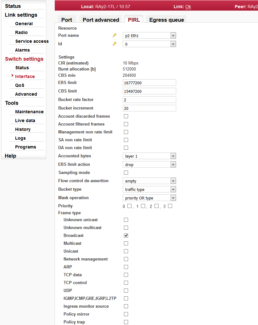
Each port can be assigned up to five different ingress rate resources.
Each resource defines a rule (filter) for the incoming frame. If the rule is met, the frame is affected (as set by the EBS limit action parameter). If the incoming frame does not meet any rule, it is not affected by PIRL. The frame is accepted and forwarded further to the switch engine.
| ||||||||||||||||||||||
| ||||||||||||||||||||||
| ||||||||||||||||||||||
| ||||||||||||||||||||||
| ||||||||||||||||||||||
| ||||||||||||||||||||||
| ||||||||||||||||||||||
| ||||||||||||||||||||||
| ||||||||||||||||||||||
| ||||||||||||||||||||||
| ||||||||||||||||||||||
| ||||||||||||||||||||||
| ||||||||||||||||||||||
| ||||||||||||||||||||||
| ||||||||||||||||||||||
| ||||||||||||||||||||||
| ||||||||||||||||||||||
| ||||||||||||||||||||||
| ||||||||||||||||||||||
| ||||||||||||||||||||||
| ||||||||||||||||||||||
| ||||||||||||||||||||||
See also Output queue diagram.
| |||||||||||||||||||||||||||||||
| |||||||||||||||||||||||||||||||
| |||||||||||||||||||||||||||||||
| |||||||||||||||||||||||||||||||
| |||||||||||||||||||||||||||||||
| |||||||||||||||||||||||||||||||
| |||||||||||||||||||||||||||||||
Quality of Service (QoS) is the ability to provide different priorities to different applications, users, or data flows, or to guarantee a certain level of performance to a data flow. QoS using 802.1p and DSCP are implemented.
The ingress block has the task of determining the priority of each frame to be used for the internal Queue Controller (QPri) as well as the priority assigned to the frame (FPri) if the frame egresses the switch tagged. The classification as to if the frame is discard eligible is also determined. The Ingress block does not perform the QoS switching policy, which is the task of the Queue Controller. Instead, it has the job of determining the QPri and FPri assigned to each frame for the Queue Controller and Egress block.
See the Functional diagram.
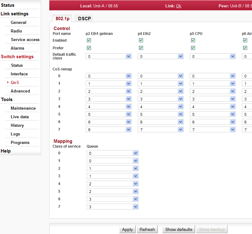
The IEEE 802.1p QoS technique also known as class of service (CoS), is a 3-bit field called the Priority Code Point (PCP) within an Ethernet frame header when using VLAN tagged frames as defined by IEEE 802.1Q. It specifies a priority value of between 0 and 7 inclusive that can be used by QoS disciplines to differentiate traffic. The value 0 is generally taken as the lowest priority and 7 as the highest priority.
| |||||||
| |||||||
| |||||||
| |||||||
| |||||||
| |||||||
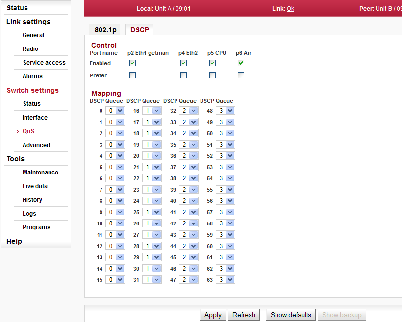
The DSCP stands for Differentiated services Code Point which is a 6-bit value stored within the IP header. The QoS techniques using those bits are called DiffServ or Differentiated services.
| |||||||
| |||||||
| |||||||
| |||||||
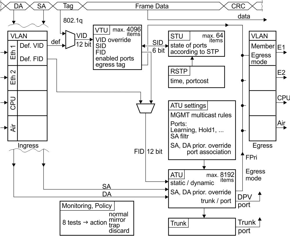
According to the Advanced menu proceeds the deciding, through which port the framework should be transmitted from RAy unit.
The processing of framework can be observed on the diagram and in the table. Table columns indicate successive steps and in the rows there is hinted the development of framework parameters.
| Frame | VLAN | VTU | STU | ATU | Trunk | |
|---|---|---|---|---|---|---|
| DA, SA | DA, SA | id | ||||
| QPri | QoS, DSCP | by port | by VLAN | DA, SA | ||
| VID | VID | def. VID | id | |||
| SID | SID | id | ||||
| FID | by port | by VLAN | id | |||
| Trunk | ATU-Trunk | id | ||||
| port egress | by port | RSTP | ATU-Port | Trunk | ||
| tag egress | Egress mode | Member tag |
An indicative description of the function of each block:
Frame
An incoming frame contains the destination MAC address DA and the source address SA. The VLAN 802.1p priority can be contained in the Ethernet header and the DSCP priority in the IP header. If the frame is a member of a VLAN, it carries it’s VID number and 802.1q priority in the tag.
VLAN
A frame is received through ports Eth1, Eth2, Air or from microwave CPU. The head of the frame may change at this time based on parameters set in the VLAN menu.
All untagged frames are assigned a VID. A tagged (VLAN) framework can have its own VID overwritten by a default VID.
The packet priority can be overwritten according to parameter menus QoS, VLAN and ATU.
The FID for searching in the ATU table is allocated to the frame within the VLAN menu (by the input port) or from the corresponding VID in the VTU table.
Member parameter can limit the allowed output direction of ports.
Frames sent from a unit transfers through an output port. The Egress mode parameter bound to the port either adds or removes the VLAN tag.
VTU
Values in the VID determine search results from the VTU table. These are created manually. The SID index (enabled ports in terms of STP) FID index (for searching in the address table ATU) taken from this search result are assigned to the frame. This FID will overwrite the FID from menu VLAN.
Based on this, the VTU can also overwrite the priority of this frame.
The permitted output ports and method of working with VLAN tag on the output are also defined here.
STU
The Spanning tree protocol in this table maintains the status of ports from the viewpoint of the authorized network throughput and the learning of routing. Protocol MSTP is used.
Each VTU entry uses some of the entries in the STU. Entries in the ATU are created in accordance with these assigned states.
The port state behaviour is determined by the STP.
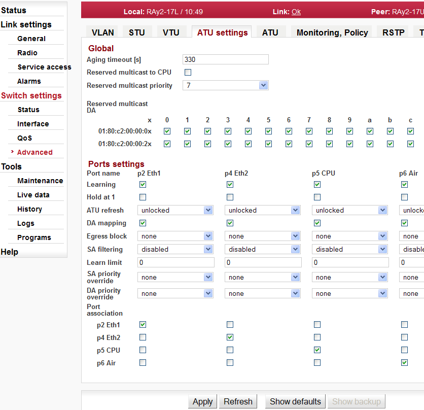
ATU settings
Any assigned parameters dictate how the ATU table should be used.
The Global section of this menu provides for passage of MGMT frames (e.g. BPDU).
In the Port settings section, the behaviour of individual port is defined:
– Behaviour of the ATU table in terms of automatically creating records (Learning, Hold at 1, ATU refresh, Learn limit).
– Discarding frames according to the source addresses.
– Handling frames with unfamiliar destination addresses.
– The frames’ priority can be overridden by the SA or the DA.
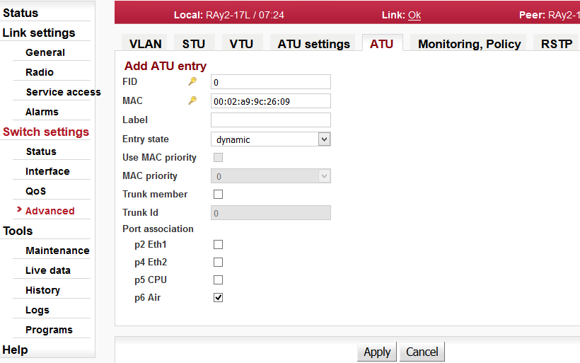
ATU
The ATU table determines the output port on the RAy according to the DA in the frame.
Records are arranged according to the FID and the MAC addresses.
The table is created and maintained based on informations contained in incoming frames (learning). Manual recording is also possible.
The record can be dynamic or static.
Priority frames with a static record can be overridden by the SA or DA.
The results of searching the ATU provide the set of output ports or trunk number.
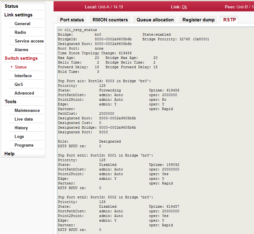
RSTP
The RSTP demon turns off redundant paths through the network (switch ports), or re-activates them in the case of failure in other branch.
The Global section of this menu contains switch priority for the RSTP and necessary time constants.
The Port settings section holds the value of each port as seen by the RSTP. This information indicates if the RSTP shuts down or restarts a redundant port if a route is interrupted.
Trunk
The Trunk enables the distribution of data load on multiple ports. The ratio of distribution is determined by parameter Balancing mode.
Abbreviations used in the Advanced menu.
DA, SA | Destination and Source frame address (MAC) |
LAN | Local Area Network |
VLAN | Virtual LAN, menu of parameters related to the VLAN |
VID | VLAN network ID |
VTU | VLAN Table Unit – according to VID assigns SID and FID to the frame |
SID | Spanning tree ID – record number for STP |
STP | Spanning Tree Protocol – prevents a loop in the network |
STU | Spanning Tree Unit – parameters associated with STP |
FID | Forwarding Information Database number – according to this runs searching in the table |
ATU | Address Translation Unit – conversion FID and DA to number of output port |
MGMT | Management frames – service frames of the microwave
link: |
BPDU | Bridge Protocol Data Unit – frames used by STP protocol |
802.1d | Spanning tree protocol by ports |
802.1s | Spanning tree protocol by VLAN |
802.1q | tagging of frames (VLAN) |
802.1p | priority by 2-nd layer (tagged frames Ethernet) |
DSCP | Differentiated Services Code Point – priority by 3-rd layer (IP packet) |
QoS | Quality of Service |
FPri | Frame Priority – priority in the network |
QPri | Queue Priority – priority of the frame inside the switch |
Trunk | here in the sense of aggregation ethernet links –
conjunction multiple ports into a single line |
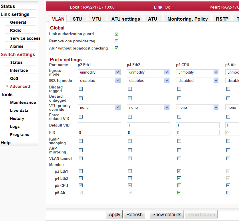
Setup of VLAN related and global parameters.
| |||||||||||||||||||||||||||||||||||||||||||||||||
| |||||||||||||||||||||||||||||||||||||||||||||||||
| |||||||||||||||||||||||||||||||||||||||||||||||||
| |||||||||||||||||||||||||||||||||||||||||||||||||
| |||||||||||||||||||||||||||||||||||||||||||||||||
| |||||||||||||||||||||||||||||||||||||||||||||||||
| |||||||||||||||||||||||||||||||||||||||||||||||||
| |||||||||||||||||||||||||||||||||||||||||||||||||
| |||||||||||||||||||||||||||||||||||||||||||||||||
| |||||||||||||||||||||||||||||||||||||||||||||||||
| |||||||||||||||||||||||||||||||||||||||||||||||||
| |||||||||||||||||||||||||||||||||||||||||||||||||
| |||||||||||||||||||||||||||||||||||||||||||||||||
| |||||||||||||||||||||||||||||||||||||||||||||||||
| |||||||||||||||||||||||||||||||||||||||||||||||||
| |||||||||||||||||||||||||||||||||||||||||||||||||
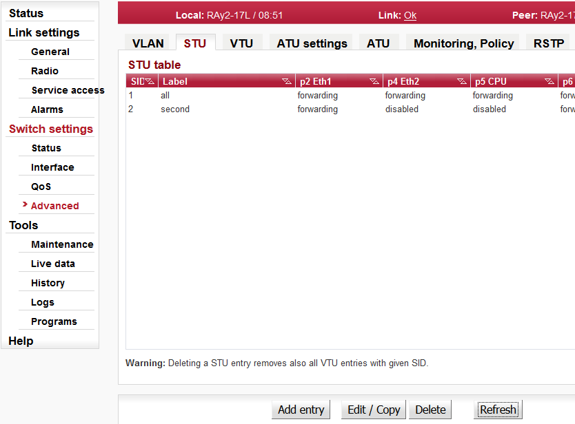
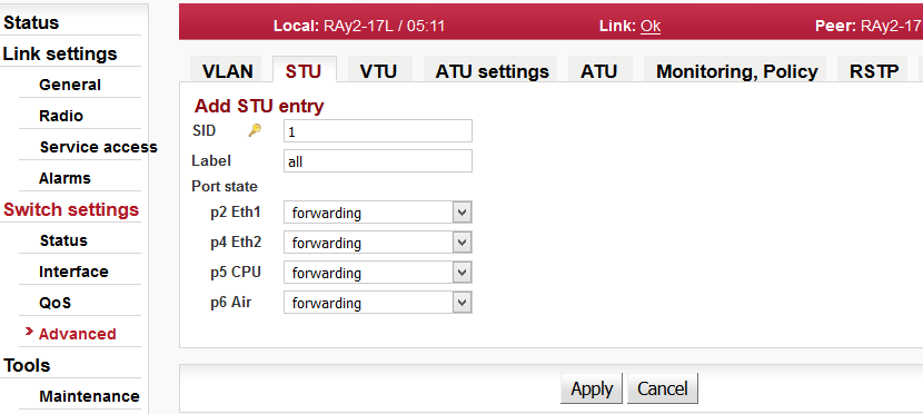
The per VLAN Spanning Tree Unit (STU) in the device supports user commands to access and modify the contents of the Port State database.
| |||||||||||||||||||
| |||||||||||||||||||
| |||||||||||||||||||
| |||||||||||||||||||
| |||||||||||||||||||
| |||||||||||||||||||
| |||||||||||||||||||
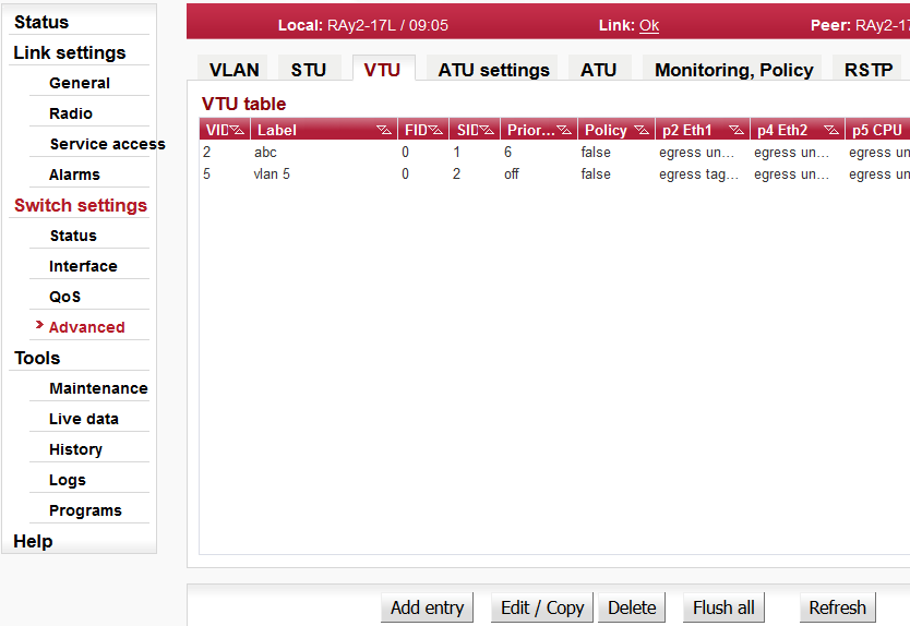
The VTU (VLAN Table Unit) records form the VLAN Table.
| |||||||||||||||||||
| |||||||||||||||||||
| |||||||||||||||||||
| |||||||||||||||||||
| |||||||||||||||||||
| |||||||||||||||||||
| |||||||||||||||||||
| |||||||||||||||||||
| |||||||||||||||||||
| |||||||||||||||||||
| |||||||||||||||||||
| |||||||||||||||||||
| |||||||||||||||||||
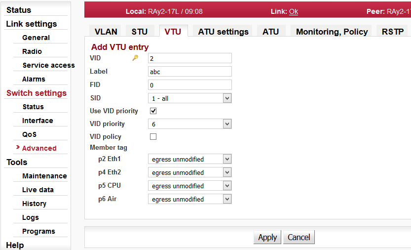
Setup of ATU (Address Translation Unit) table related parameters.
| |||||||||||||||||||||
| |||||||||||||||||||||
| |||||||||||||||||||||
| |||||||||||||||||||||
| |||||||||||||||||||||
| |||||||||||||||||||||
| |||||||||||||||||||||
| |||||||||||||||||||||
| |||||||||||||||||||||
| |||||||||||||||||||||
| |||||||||||||||||||||
| |||||||||||||||||||||
| |||||||||||||||||||||
| |||||||||||||||||||||
| |||||||||||||||||||||
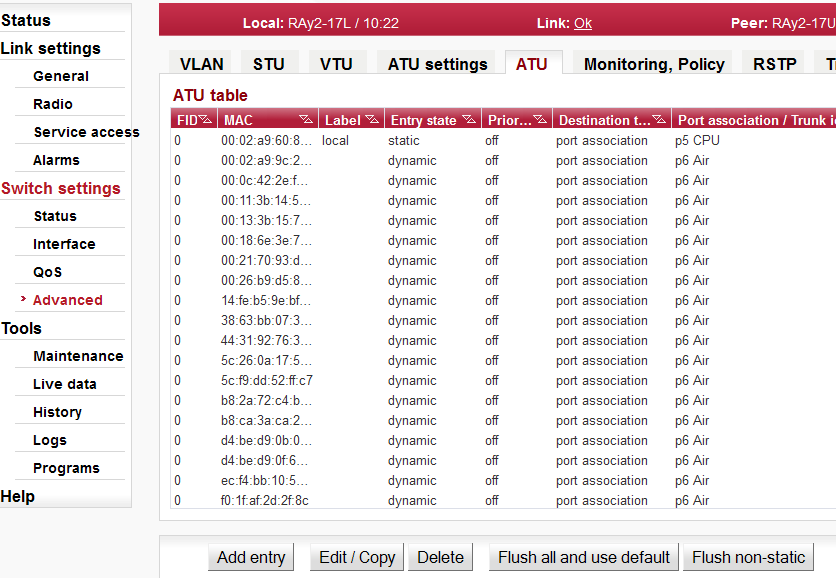
The Address Translation Unit (ATU) in the device supports user commands to access the contents of the MAC address database.
There is one static record which can not be deleted. This is the management CPU record. The unicast frames directed to management are allowed to access the CPU port. The VLAN tunnel parameter is also used to enable the AP frames to access the CPU port.
| |||||||||||||||||||
| |||||||||||||||||||
| |||||||||||||||||||
| |||||||||||||||||||
| |||||||||||||||||||
| |||||||||||||||||||
| |||||||||||||||||||
| |||||||||||||||||||
| |||||||||||||||||||
| |||||||||||||||||||
| |||||||||||||||||||
| |||||||||||||||||||
| |||||||||||||||||||
| |||||||||||||||||||
| |||||||||||||||||||
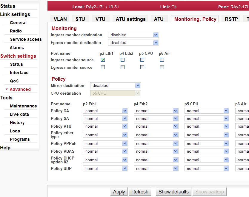
Setup of Monitoring and Policy functions.
The Policy functions allow a special handling of specific types of ingress frames.
| |||||||||||||||||||||||||||||||||||||||||||
| |||||||||||||||||||||||||||||||||||||||||||
| |||||||||||||||||||||||||||||||||||||||||||
| |||||||||||||||||||||||||||||||||||||||||||
| |||||||||||||||||||||||||||||||||||||||||||
| |||||||||||||||||||||||||||||||||||||||||||
| |||||||||||||||||||||||||||||||||||||||||||
| |||||||||||||||||||||||||||||||||||||||||||
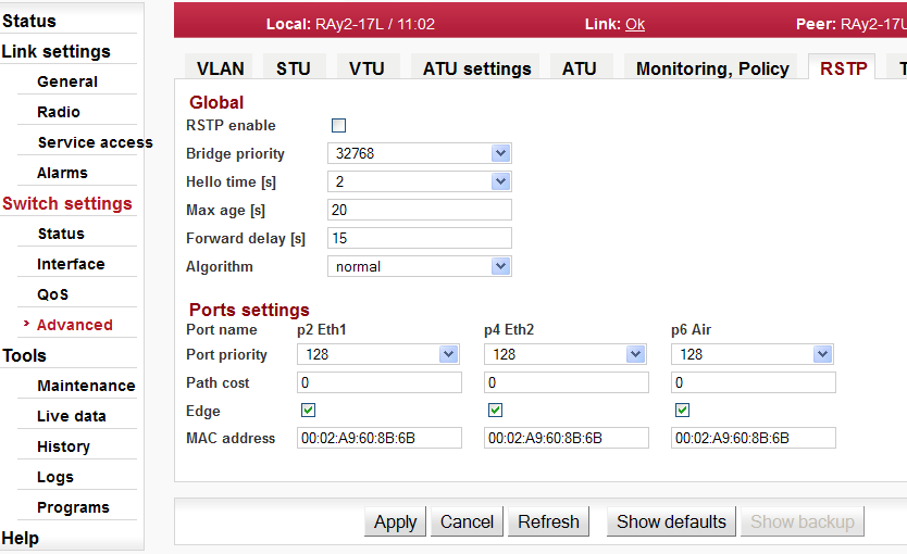
The Rapid Spanning Tree Protocol (RSTP) is a network protocol that ensures a loop-free topology for any bridged Ethernet local area network. The basic function of RSTP is to prevent bridge loops and the broadcast radiation that results from them. Spanning Tree Protocol also allows network design to include spare (redundant) links to provide automatic backup paths if an active link fails, without the danger of bridge loops, or the need for manual enabling/disabling of these backup links.
| |||||||||||
| |||||||||||
| |||||||||||
| |||||||||||
| |||||||||||
| |||||||||||
| |||||||||||
| |||||||||||
| |||||||||||
| |||||||||||
| |||||||||||
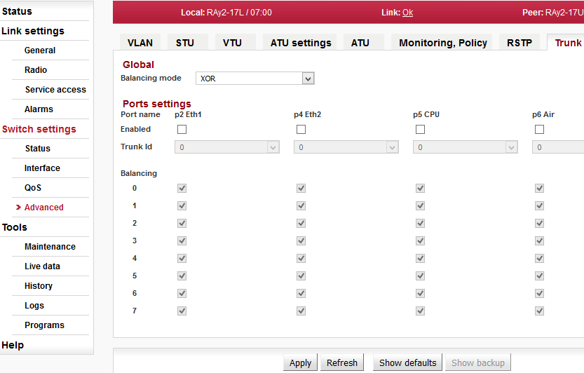
Port trunking is supported by the device using any combinations of ports. The ports that are to be associated with the trunk need to have all the port members’ defined with the same “Trunk Id” and the “Enabled” parameter has to be enabled.
When a frame enters a Trunk Port its Source Address (SA) is learned with its association to the ingress port’s TrunkID number. In this way the contents of the address database contain the same association with the frame’s SA regardless of the link of the trunk the frame entered the switch.
When frames are routed back toward a trunk the frame will have its Destination Address (DA) found from the address database. If the frame’s DA is unknown the frame will try to flood out all ports of the trunk (this is OK in so far as this will be fixed with load balancing). If the frame’s DA is found, the entry will indicate mapping to a trunk and the entry’s DPV bits will contain the TrunkID associated with this frame’s DA. This TrunkID needs to be converted into a DPV (Destination Port Vector) that the rest of the switch can use. This is accomplished by accessing the Trunk Mapping table using the TrunkID that was in the ATU’s entry.
| ||||||||||
| ||||||||||
| ||||||||||
| ||||||||||
| ||||||||||
|
| ||||||||||||||||||
|
| ||||||||||||||||||
|
| ||||||||||||||||||
|
| ||||||||||||||||||
|
| ||||||||||||||||||
| |||||||||||||||||||
| |||||||||||||||||||


The sub-set of RAy parameters is affected by use of SW Feature keys.
The SW Feature keys limiting data transfer speed [Mbps] are available. Speed of the transferred data is determined by a combination of the radio channel bandwidth (parameter Bandwidth [MHz]) and modulation order (parameter TX modulation). The key limiting the data transfer speed enables only certain combinations of the channel bandwidth and modulation order to get the data transfer speed according to the key. The data transfer speed is typically slightly higher than declared.
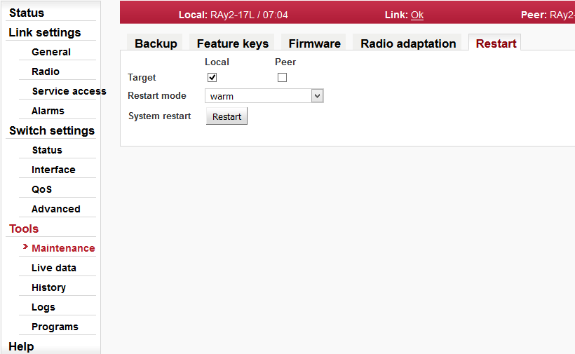
When installed, the key is activated after the unit restart. The unit can be restarted using the Tools – Maintenance – Restart. Choose the Restart mode – warm.
| |||||||
| |||||||
| |||||||
| |||||||
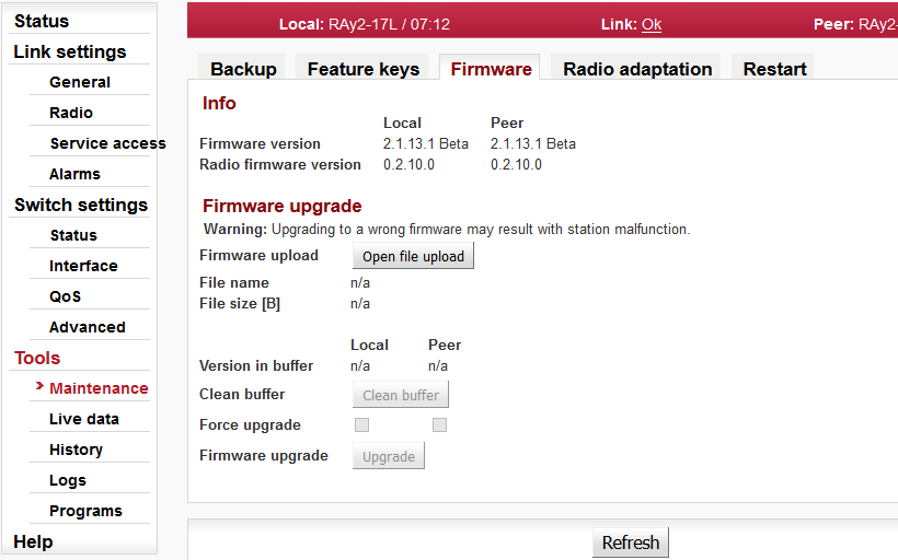
If a new firmware version is released for the given microwave link type, you can upload it to your RAy units.
| Info | |||||
| |||||
| |||||
| |||||
| |||||
| |||||
| Firmware upgrade | |||||
| |||||
| |||||
| |||||
| |||||
| |||||
| |||||
| |||||
| |||||
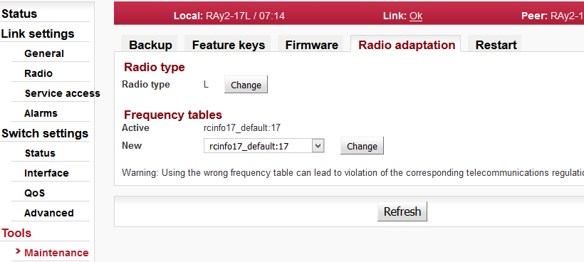
| |||||||||||||||||||||||||
| |||||||||||||||||||||||||
| Warning | |
|---|---|
Using the wrong frequency table can lead to violation of the corresponding telecommunications regulations. |
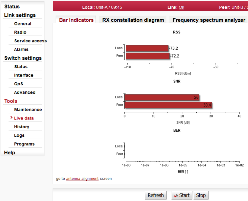
Graphical indication of BER, SNR and RSS.
| ||
|
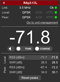
The Antenna Alignment Tool supports interactive antenna alignment. RSS and SNR are displayed for both local and peer unit. A selected value can be indicated in large font and acoustically. Values are refreshed 10x per second.
When performing antenna alignment, both ATPC and ACM functions should be disabled; their automatic behaviour interferes with the alignment process which is based on finding the maximum signal strength.
The tool is accessed via e.g. http://192.168.169.169/tk for standard Ethernet ports, and via http://172.17.17.17/tk for connections using USB/WiFi or USB/Eth. The Antenna Alignment Tool does not require user authentication.
| Red strip
(top of the page) |
| |||||||||
| ||||||||||
| ||||||||||
| ||||||||||
| ||||||||||
| ||||||||||
| ||||||||||
| ||||||||||
| ||||||||||
| ||||||||||
| ||||||||||
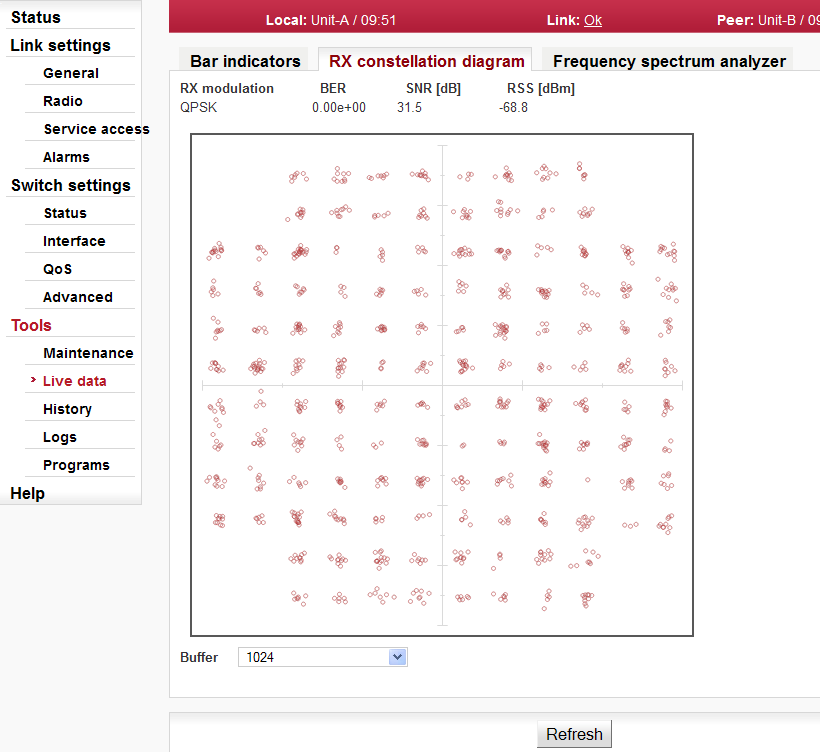
Constellation diagram shows the quality of received signal.
| ||
| ||
|
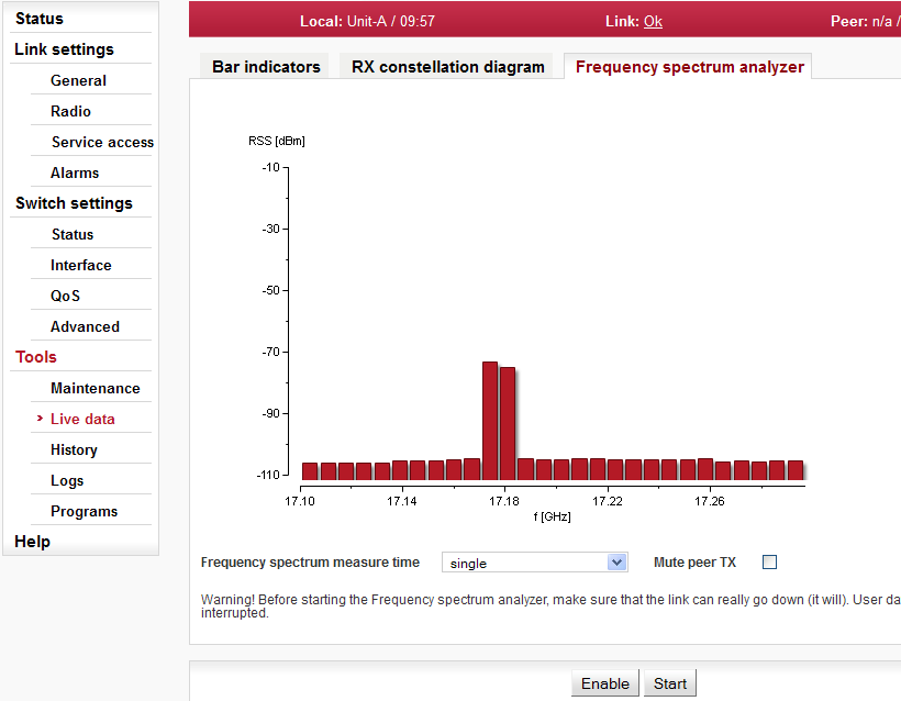
A very useful tool for identifying in-band interference and locating a free channel. It is not a full-blown spectrum analyzer as it scans the spectrum with 7MHz channel resolution. The accuracy of measured results is given by the accuracy of measuring RSS.
| Warning | |
|---|---|
Running spectrum measurement causes interruption of user data flow between stations! |
| |||
| |||
| |||
|
After using the analyzer visit any of the Link menu settings and select Refresh. This restores the configuration connection (message Peer: n/a ).
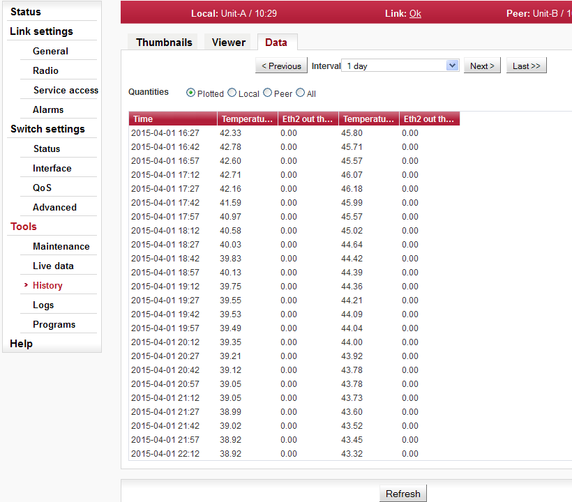
The unit continuously stores information about the values of important variables. Stored values can be viewed using three methods – Thumbnails, Viewer and Data
Preview all values for the last 24 hours. Click on a thumbnail to open the viewer with a chart.
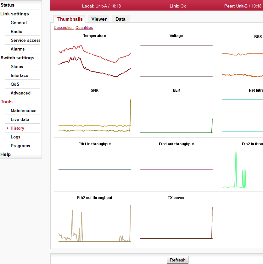
| Instantaneous value of temperature inside the unit. Measured on the modem board. Temperature of radio board is available via SNMP. | |
| Instantaneous value of unit supply voltage. | |
| Received signal strength. | |
| Signal-to-noise ratio of the received signal. | |
| Instantaneous bit error rate on link. | |
| Instantaneous transmission capacity. | |
| Instantaneous speed (20s average) of incoming user data on the user Ethernet port. | |
| Instantaneous speed (20s average) of outgoing user data on the user Ethernet port. | |
| Instantaneous value of transmission power. |
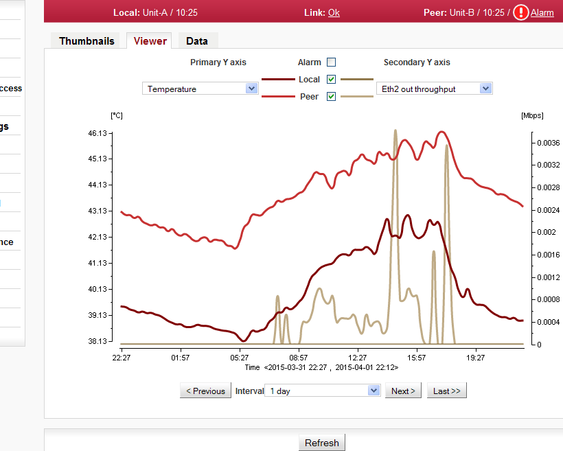
Detailed graphical view of one or two selected values for the given interval. You can choose to view data from Local or Peer or both.
| |||||||||||||||||||||||||||||||||||||
| |||||||||||||||||||||||||||||||||||||
| |||||||||||||||||||||||||||||||||||||
| |||||||||||||||||||||||||||||||||||||
| |||||||||||||||||||||||||||||||||||||
Shows internal unit logs. Individual tabs allow total or filtered view.
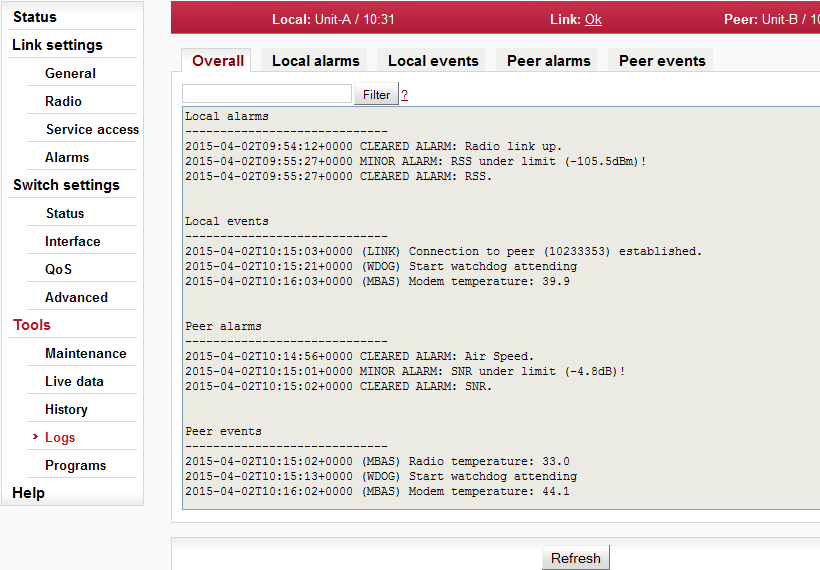
When you first open the screen, it is necessary to start browsing logs by pressing the Refresh button.
Maximum length of displayed logs is 250 entries. If you need to display longer history, use of CLI interface is needed.
| |||
| |||
| |||
|
The Ping tool allows sending ICMP pings to a selected address
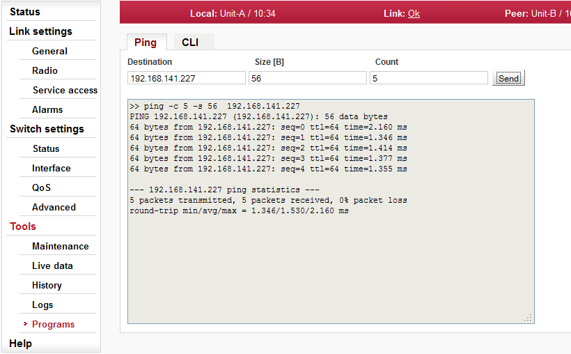
Start the test by clicking on Send. The result is displayed in the text window.
| |||
| |||
|
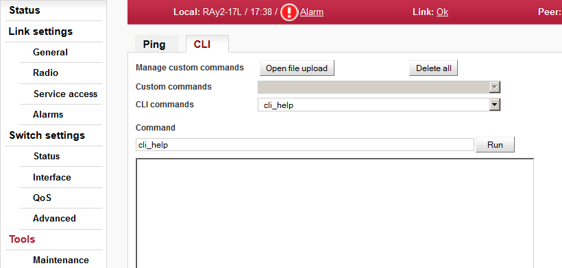
Web interface for executing non-interactive scripts and programs.
| |||||
| |||||
| |||||
| |||||
| |||||
#!/bin/sh
#script checkes if service with the same name or vid already exists
#if not creates a new entry in VTU with given VID
#
#  input parameters:
#      service_name - name of the new service
#      VID - vid of the new service
#
#  return values:
#      0 - ok
#      3 - bad parameter
#      5 - service already exists
#      6 - there already exists an entry with given VID
#     42 - other error

D42_NAME="$1"
D42_VID="$2"

D42N="service_data42"

error()
{
        echo "$D42N: Error: $*" >&2
}

info()
{
        echo "$D42N: $*" >&2
}

die()
{
        error "$*"
        exit 42 #error
}

# basic check if not empty
if [ -z "$D42_NAME" ]; then
        error "Bad service name"
        exit 3
fi
if [ -z "$D42_VID" ]; then
        error "Bad service VID"
        exit 3
fi

D42_FOUND=$(cli_nw_get --vtu all | grep "$D42_NAME")
if [ -n "$D42_FOUND" ]; then
        error "Service(s) with name $D42_NAME found"
        echo $D42_FOUND
        exit 5
fi

D42_VALID=$(cli_nw_get --vtu "$D42_VID" | sed -n 's/^valid=\(.\+\)$/\1/p')
if [ "pre_$D42_VALID" = "pre_true" ]; then
        error "VID $D42_VID is used"
        cli_nw_get --vtu "$D42_VID"
        exit 6
fi

D42_VALID=$(cli_nw_get --stu 1 | sed -n 's/^valid=\(.\+\)$/\1/p')
if [ "pre_$D42_VALID" = "pre_false" ]; then
        info "Creating STU entry with SID=1"
        cli_nw_set --stu 1 'label="D42_auto", port_state=["disabled", "disabled", "forwarding", "disabled", "disabled", "forwarding", "forwarding"]'
        if [ $? -ne 0 ]; then
                die "Failed to create STU entry"
        fi
fi

info "Creating service \"$D42_NAME\" with VID=$D42_VID"
cli_nw_set --vtu "$D42_VID" label="$D42_NAME" 'fid=0, sid=1, pri_override=true, priority=5, policy=false, member_tag=["unmodify", "unmodify", "tag", "unmodify", "not_member", "not_member", "unmodify"]'
if [ $? -ne 0 ]; then
        die "Failed to create service \"$D42_NAME\" with VID=$D42_VID"
fi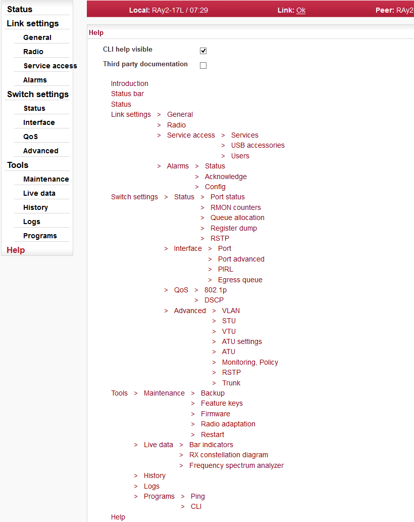
Help from Help menu
The Help screen displays contents of the embedded help. The help text is displayed in the whole configuration window. The text structure corresponds to individual configuration screens. Every item of this Help opens the specific help menu.
| ||
|
Help from configuration menu
Clicking the name of the specific parameter in the configuration menu brings up the help belonging to this parameter. The help text is displayed in the pop up window:

There is a Go to help link within the help text. It displays the whole configuration menu help:
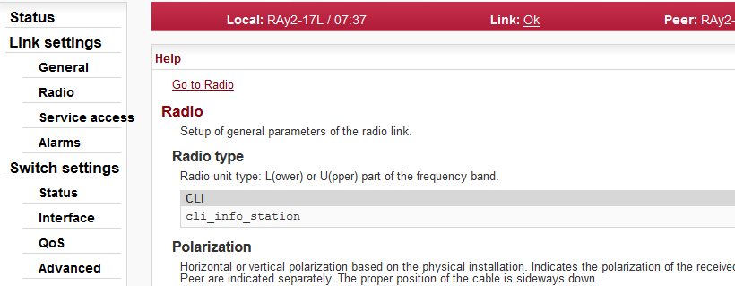
There is a link on each help screen which points to the respective configuration screen.
Clicking the question mark icon in the upper right corner of the configuration screen brings a summary help for the configuration screen in the pop up window:
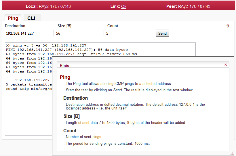
The Help window can be moved by dragging the Hints bar. Resize it by dragging the bottom corner.