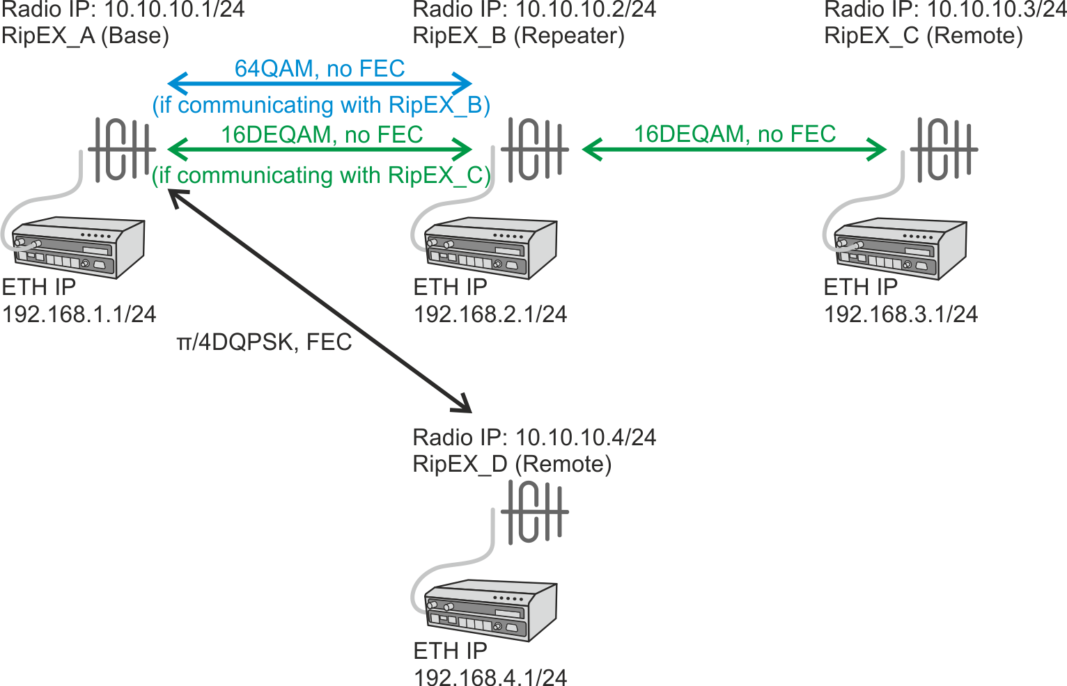
RipEX2 radios can communicate with neighbouring RipEX2 units via different modulation rates, e.g., a central RipEX2 radio communicates with 10 remote radios and for each of those remote radios, it can configure individual modulation rate, FEC and ACK.
| Important | |
|---|---|
We really recommend using the most robust modulation as the “basic” one and using higher modulations for individual link options. See the respective chapters for details. |
The following picture gives an example of a network layout.
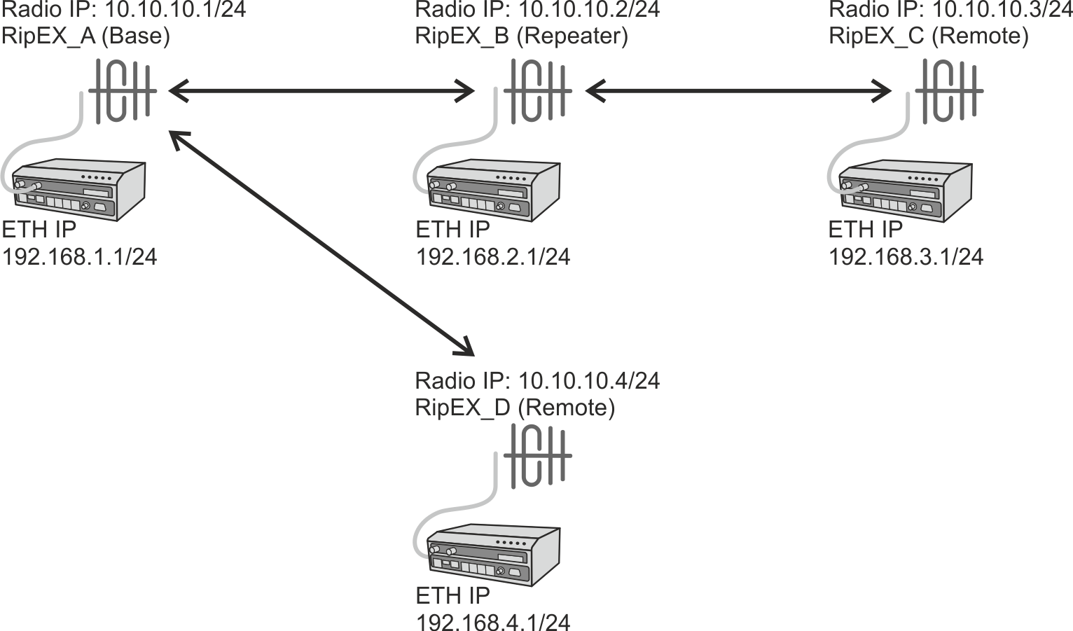
In the following sections, all RipEX2 units will be configured and Flexible/BDP differences will be explained.
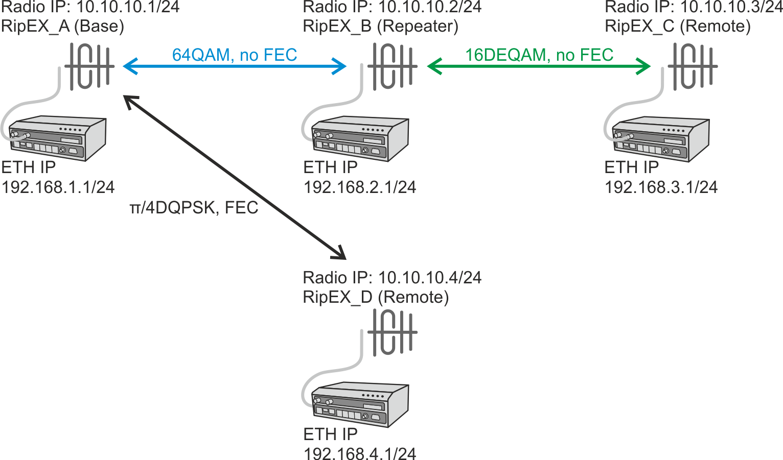
In Flexible protocol, each individual radio link can be configured with different settings (modulation rate, FEC, ACK). In Fig. 2.2, “Flexible protocol individual link options” three radio links are configured, each with different settings.
| Note | |
|---|---|
Please see Section 2.2, “Base Driven Protocol” for differences. |
| Important | |
|---|---|
As already mentioned in Chapter 1, Autospeed, using the most robust modulation for the “basic” modulation is recommended. In a Flexible protocol the main reason is that broadcast data are sent on this modulation (no matter of individual link options). If RipEX would use e.g. 16DEQAM modulation on a link which requires π/4DQPSK (or lower), broadcast data might not be sent and received successfully causing a badly working link (e.g. ARP data are also broadcast). |
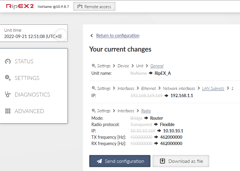
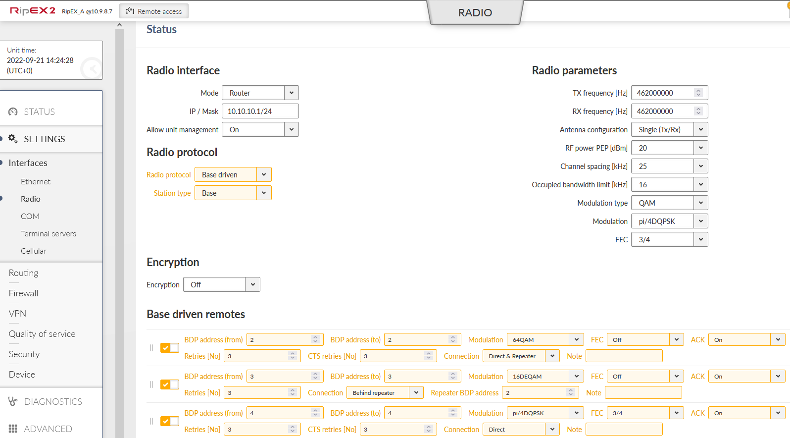
The basic configuration is simple. Just edit the following parameters:
Unit name: RipEX_A
Operating mode: Router
Radio protocol: Flexible
Radio IP: 10.10.10.1
Radio Mask: 255.255.255.0
TX/RX Frequency: 462000000 (used within this example)
Ethernet IP: 192.168.1.1
Ethernet Mask: 255.255.255.0
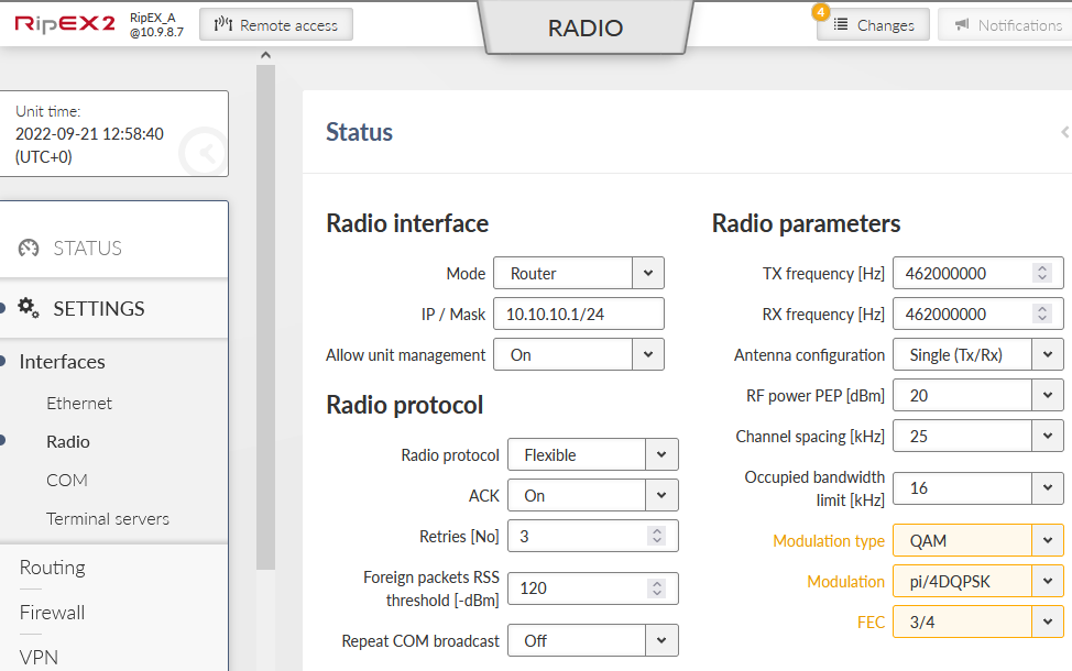
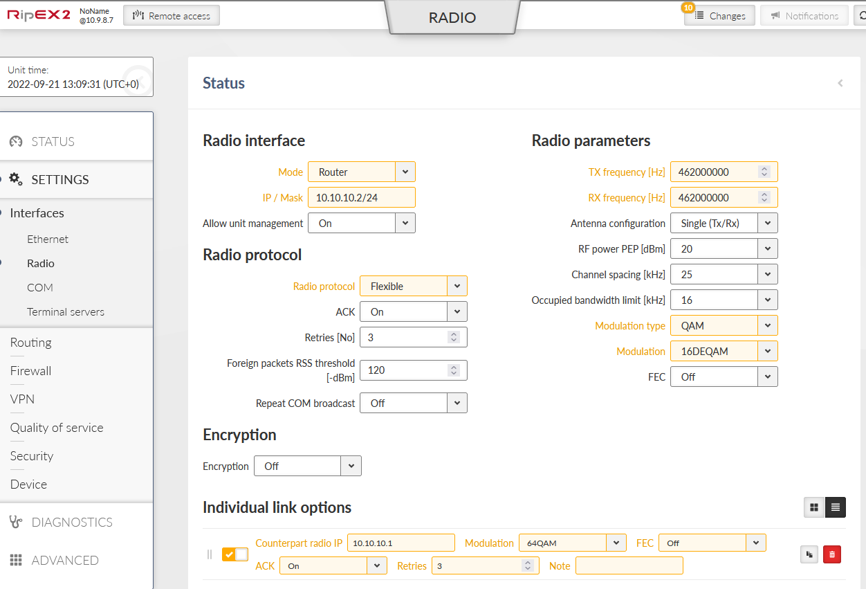
Go to the Settings – Interfaces – Radio menu and configure the details. Common (not in defaults) Radio parameters shall be:
Modulation type: QAM
Modulation rate: π/4DQPSK
FEC: 3/4
Then, in the Individual link options part of the menu, configure a higher modulation with RipEX_B:
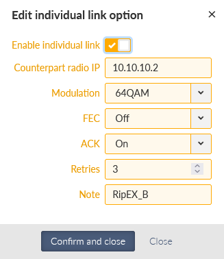
This configuration makes π/4DQPSK the default modulation (used for all radio links by default). FEC is enabled by default. The “Individual link options” line forces RipEX_A to use 64QAM modulation with disabled FEC for the radio link to RipEX_B (10.10.10.2).
| Note | |
|---|---|
In Flexible protocol, modulation rate must be configured in all RipEX2 units. In BDP, modulation rates are controlled by the Base station configuration (remote units must comply with Modulation type only). |
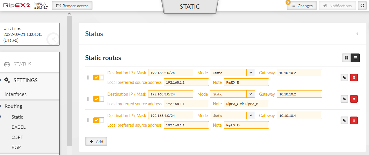
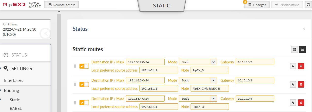
Three routes are added – accessibility of all remote Ethernet subnets.
192.168.2.0/24 via 10.10.10.2 (direct link)
192.168.3.0/24 via 10.10.10.2 (RipEX_B is used as a repeater)
192.168.4.0/24 via 10.10.10.4 (direct link)
| Note | |
|---|---|
We force to use 192.168.1.1 as the Source address for locally generated packets, because otherwise it will automatically use Radio IP 10.10.10.1. This IP (segment) might not be correctly routed over the repeater. |
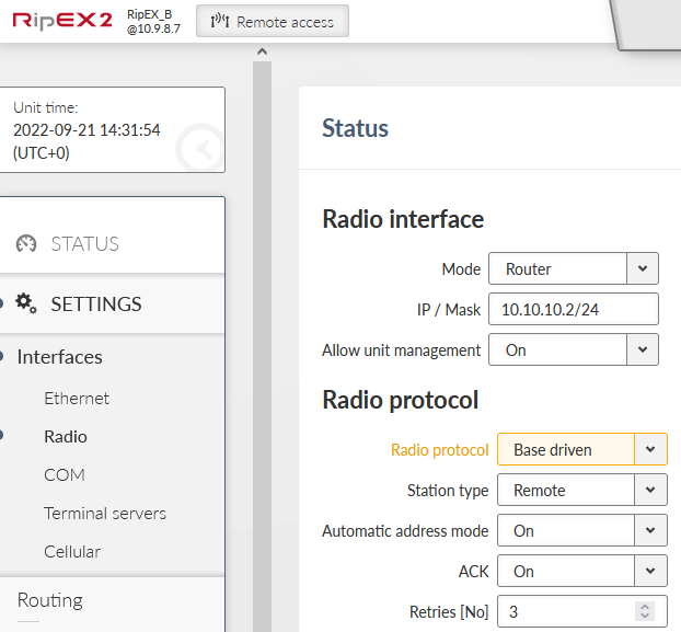
Parameters different from RipEX_A:
Unit name: RipEX_B
Radio IP: 10.10.10.2
Ethernet IP: 192.168.2.1
RipEX_B common modulation is 16DEQAM and no FEC. In the individual link options, we have one neighbour 10.10.10.1 utilizing 64QAM modulation.
RipEX_B will always use 16DEQAM modulation rate (without FEC) when communicating with RipEX_C (10.10.10.3) and for all broadcast data thanks to default/basic modulation. Modulation back to RipEX_A is set to the higher 64QAM modulation.
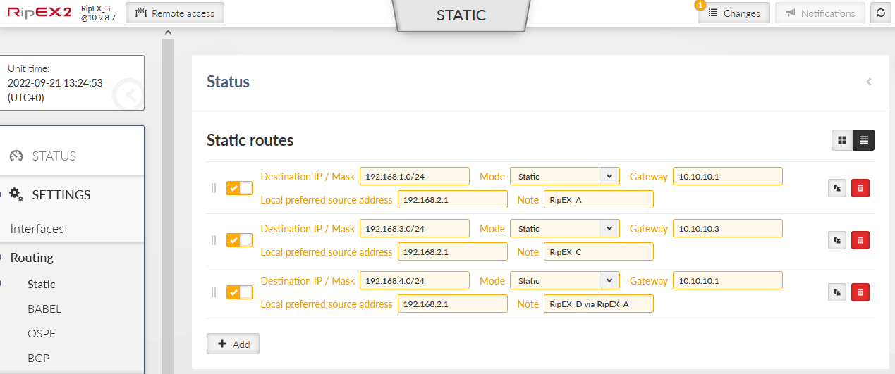
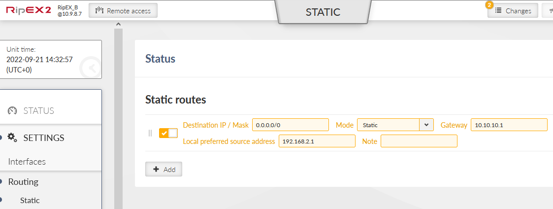
Don’t forget to set up Routing rules.
192.168.1.0/24 via 10.10.10.1 (direct link)
192.168.3.0/24 via 10.10.10.3 (direct link)
192.168.4.0/24 via 10.10.10.1 (RipEX_A is used as a repeater)
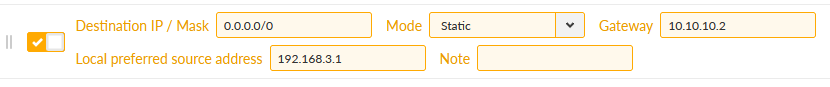
RipEX_C has no individual link option; it only communicates with RipEX_B via 16DEQAM modulation and no FEC. All routing rules to remote networks are via 10.10.10.2 (RipEX_B) so a default gateway (0.0.0.0/0) can be used.
RipEX_D is the same as RipEX_C, but it uses π/4DQPSK and ¾ FEC. It sends all the data to RipEX_A (10.10.10.1).
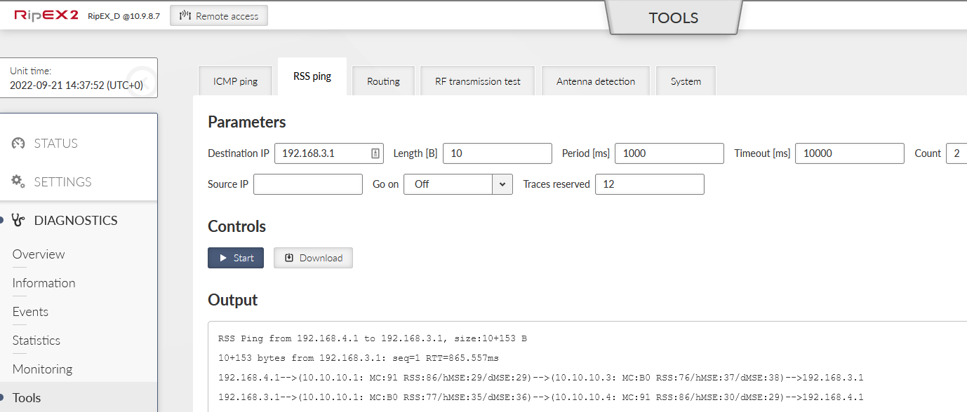
One RSS ping can display all required information. Issue the RSS Ping from RipEX_D to RipEX_C. Do it from DIAGNOSTICS – Tools – RSS ping menu. Use the Ethernet IP addresses.
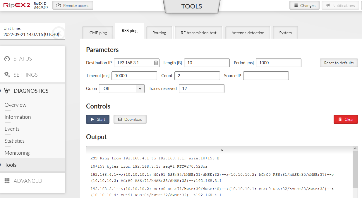
The RSS ping output shows 3 radio hops in each direction, in total 6 radio hops. See the highlighted MC values (Modulation codes).
192.168.4.1–>(10.10.10.1: MC:91 RSS:84/hMSE:31/dMSE:32)–>(10.10.10.2: MC:C0 RSS:81/hMSE:35/dMSE:37)–>(10.10.10.3: MC:B0 RSS:71/hMSE:33/dMSE:35)–>192.168.3.1
192.168.3.1–>(10.10.10.2: MC:B0 RSS:71/hMSE:39/dMSE:40)–>(10.10.10.1: MC:C0 RSS:82/hMSE:33/dMSE:33)–>(10.10.10.4: MC:91 RSS:84/hMSE:32/dMSE:32)–>192.168.4.1
MC:91 – π/4DQPSK & FEC On, used for the Radio link between RipEX_D and RipEX_A
MC:C0 – 64QAM & FEC Off, used for the Radio link between RipEX_A and RipEX_B
MC:B0 – 16DEQAM & FEC Off, used for the Radio link between RipEX_B and RipEX_C
The direction back is the same in our example. In Flexible mode, it is even possible to define different settings for different directions of one radio link. This is not possible in BDP.
| Note | |
|---|---|
You can also check modulation codes in Radio Monitoring. |
Complete list of modulation codes:
Tab. 2.1: Translation table for Modulation rates and FEC
| Modulation | FEC | |
|---|---|---|
| 00 | 2CPFSK | FEC off |
| 01 | FEC 3/4 | |
| 10 | 4CPFSK | FEC off |
| 11 | FEC 3/4 | |
| 80 | DPSK | FEC off |
| 81 | FEC 3/4 | |
| 90 | π/4DQPSK | FEC off |
| 91 | FEC 3/4 | |
| A0 | D8PSK | FEC off |
| A1 | FEC 3/4 | |
| B0 | 16DEQAM | FEC off |
| B1 | FEC 3/4 | |
| C0 | 64QAM | FEC off |
| C1 | FEC 3/4 | |
| D0 | FEC 5/6 | |
| D1 | FEC 2/3 | |
| E0 | 256QAM | FEC off |
| E1 | FEC 3/4 | |
| F0 | FEC 5/6 | |
| F1 | FEC 2/3 |
Base Driven protocol is slightly different in the way it handles individual link options. In BDP, all communication is strictly controlled by the Base station and this Base station configures all modulation rates within the whole network. Individual remote units must comply with the Modulation type; ACK can be configured at each remote unit separately.
| Important | |
|---|---|
Always set the basic/default modulation to the most robust option (i.e., the lowest modulation required in one BDP network). This modulation is used for all BDP overhead data so all the units within the network must receive such data correctly. User data traffic is sent based on “Remotes” table rules explained on the following pages. |
In Fig. 2.11, “Base Driven protocol – Individual link options” you can see two Modulation rates for one Radio link between RipEX_A and RipEX_B. This is due to BDP behaviour. If the Base station is communicating with RipEX_B, it uses 64QAM modulation rate. But if it communicates with RipEX_C, it uses 16DEQAM for the whole path (i.e., for those two Radio hops and the way back as well). It is not possible to configure it as in the Flexible mode.
| Note | |
|---|---|
If there was another RipEX2 behind RipEX_B (repeater), we could configure the communication via another Modulation rate, e.g., π/4DQPSK. And when communicating with this unit, the Radio hop between RipEX_A and RipEX_B will utilize this π/4DQPSK Modulation rate. |
Another difference is that all the communication goes over the Base station. Even if we had a direct Radio link between RipEX_D and RipEX_C, the communication must go over the Base station (RipEX_A).
See the following configuration example of how to configure the same network as in Section 2.1, “Flexible Protocol”, but using BDP.
Change the Protocol to Base driven and type to Base.
The Individual link options submenu disappeared, but a very important submenu “Base driven remotes” has appeared and can be configured. All remote units must be configured in this table, otherwise they will not be accessible. Configure all three remote units:
Protocol address: 2
Modulation rate: 64QAM
FEC: Off
ACK/CTS: Enabled (3, 3)
Connection: Direct & Repeater
Protocol address: 3
Modulation rate: 16DEQAM
FEC: Off
ACK: Enabled (3)
Connection: Behind Repeater (2)
Protocol address: 4
Modulation rate: π/4DQPSK
FEC: On
ACK/CTS: Enabled (3, 3)
Connection: Direct
| Note | |
|---|---|
Please see the details in BDP application notes. |
| Important | |
|---|---|
Configured modulation will be used for all the user data traffic between particular units. The overhead data are sent on the basic modulation (π/4DQPSK in our case). |
Different modulation rates are used for each remote station. If the Base communicates with RipEX_C (10.10.10.3), it uses 16DEQAM for all radio hops on its path (even for the link RipEX_A <-> RipEX_C).
Important change must be done in the Routing menu as well.
Route to 192.168.3.0/24 must go through 10.10.10.3 now. It goes via the repeater due to Base driven remotes configuration.
All the remote RipEX2 units have the same configuration. Change the Radio protocol to BDP and the station type to “remote”.
In the Routing menu, configure only the default route to 10.10.10.1, because all the communication is routed over the Base station.
The test will be the same – RSS ping from RipEX_D to RipEX_C.
In BDP, only the last hop is displayed in path to/from the Base unit. I.e. there are only two hops displayed for each direction, instead of three.
192.168.4.1–>(10.10.10.1: MC:91 RSS:86/hMSE:29/dMSE:29)–>(10.10.10.3: MC:B0 RSS:76/hMSE:37/dMSE:38)–>192.168.3.1
192.168.3.1–>(10.10.10.1: MC:B0 RSS:77/hMSE:35/dMSE:36)–>(10.10.10.4: MC:91 RSS:86/hMSE:30/dMSE:29)–>192.168.4.1
The first transmitted packet has the MC value 91 = π/4DQPSK with enabled FEC. The second displayed packet is from the Base station to RipEX_C utilizing 16DEQAM modulation rate without FEC (B0). The RSS ping reply utilizes 16DEQAM again as configured and the last hop uses π/4DQPSK with FEC.
| Note | |
|---|---|
Please see the details in BDP application notes. |