Since the firmware 1.6.2.0, RipEX radio improved the “Autospeed” function and added individual link options. RipEX radios can communicate with neighbouring RipEX units via different modulation rates, e.g. a central RipEX radio communicates with 10 remote radios and for each of those remote radios, it can configure individual modulation rate, FEC and ACK.
The only limitation of this feature is that all the frames have to have the same symbol rate and the same principle of modulation (i.e. CPFSK or linear).
Modulation types which can be combined within one approval type (FCC, CE or Narrow):
2CPFSK & 4CPFSK with or without FEC
or
D2PSK & π/4DQPSK & D8PSK &16DEQAM with or without FEC
| Important | |
|---|---|
We really recommend using the most robust modulation as the “basic” one and using higher modulations for individual link options. See the respective chapters for details. |
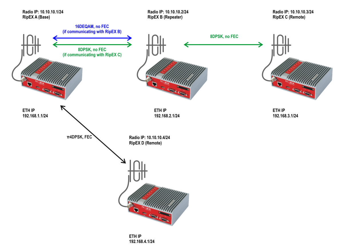
The following picture gives an example of a network layout.
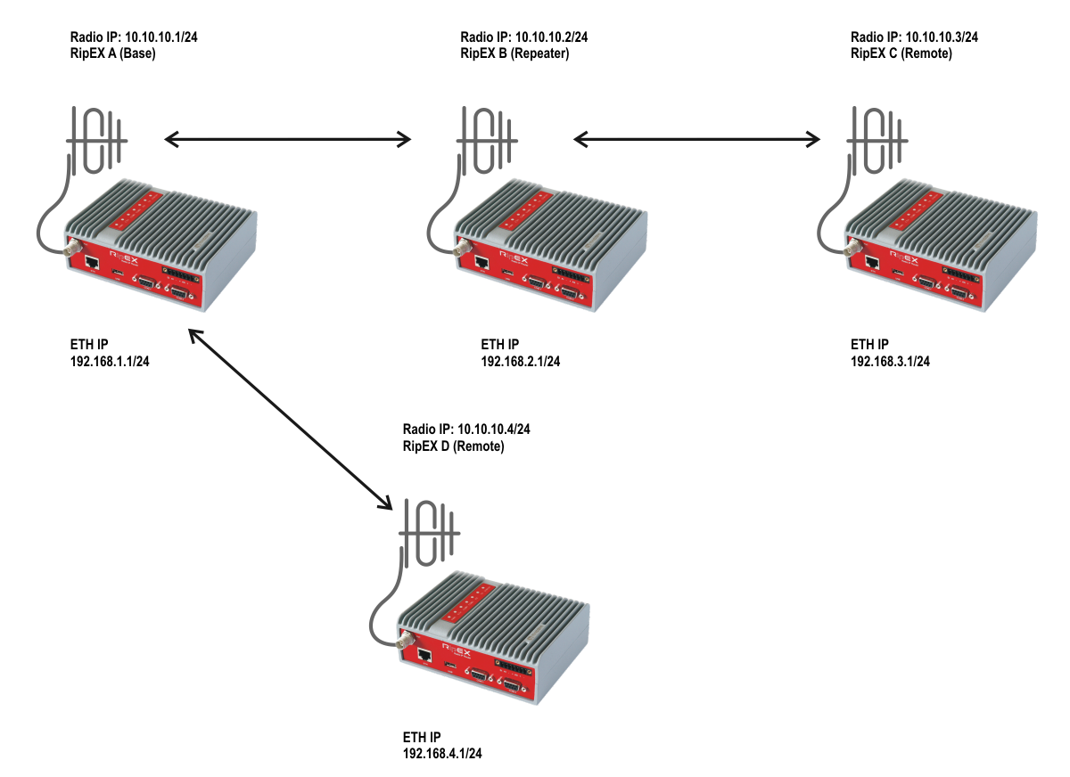
In the following sections, all RipEX units will be configured and Flexible/BDP differences will be explained.
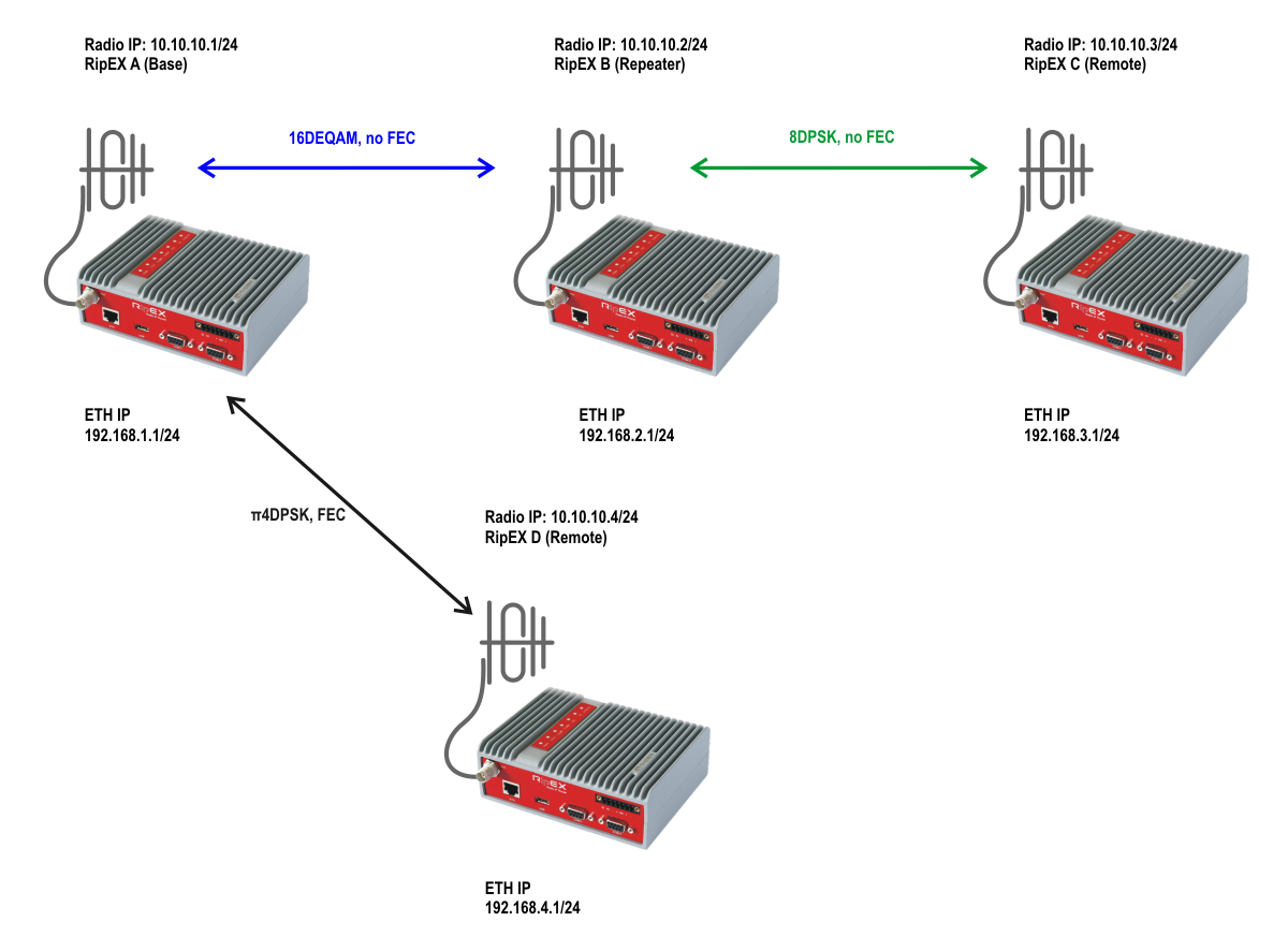
In Flexible protocol, each individual radio link can be configured with different settings (modulation rate, FEC, ACK). In the Figure 2.2 three radio links are configured, each with different settings.
| Note | |
|---|---|
Please see Section 2.2, “Base Driven Protocol” for differences. |
| Important | |
|---|---|
As already mentioned in chapter 1, using the most robust modulation for the “basic” modulation is recommended. In a Flexible protocol the main reason is that broadcast data are sent on this modulation (no matter of individual link options). If RipEX would use e.g. 16DEQAM modulation on a link which requires π/4DQPSK (or lower), broadcast data might not be sent and received successfully causing a badly working link (e.g. ARP data are also broadcast). |

The basic configuration is simple. Just edit the following parameters:
Unit name: RipEX A
Operating mode: Router
Radio IP: 10.10.10.1
Radio Mask: 255.255.255.0
TX/RX Frequency: 432.000.000 (used within this example)
Ethernet IP: 192.168.1.1
Ethernet Mask: 255.255.255.0
And after these changes, open Radio protocol details – e.g. click on the “Radio protocol” button. A new pop-up menu appears:
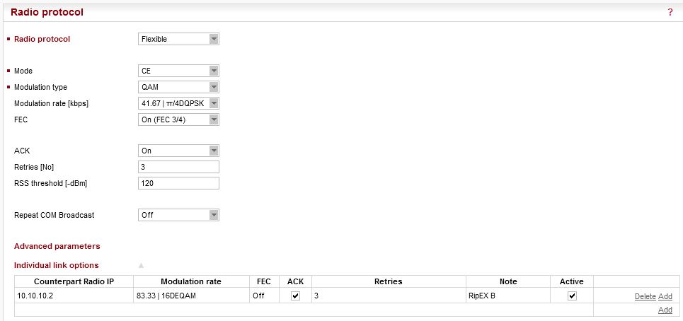
Radio protocol: Flexible
Mode: CE
Modulation type: QAM
Modulation rate: π/4DQPSK
FEC: On
ACK: On
Retries: 3
Open the Advanced parameters “Individual link options” section and “Add” a new line.
Counterpart Radio IP: 10.10.10.2
Modulation rate: 16DEQAM
FEC: Off
ACK: On
Retries: 3
Note: RipEX B
This configuration makes π/4DQPSK the default modulation (used for all radio links by default). FEC is enabled by default. The “Individual link options” line forces RipEX A to use 16DEQAM modulation with disabled FEC for the radio link to RipEX B (10.10.10.2).
| Note | |
|---|---|
In Flexible protocol, modulation rate must be configured in all RipEX units. In BDP, modulation rates are controlled by the Base station configuration (remote units must comply with Modulation type only). |
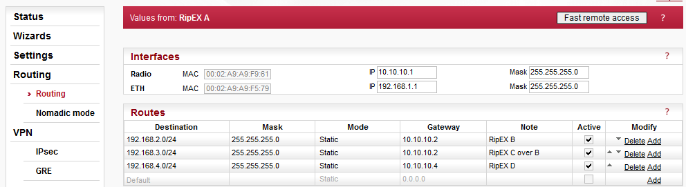
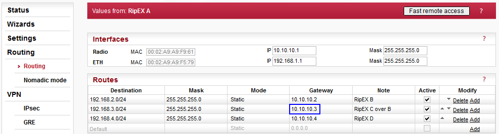
Three routes are added – accessibility of all remote Ethernet subnets.
192.168.2.0/24 via 10.10.10.2 (direct link)
192.168.3.0/24 via 10.10.10.2 (RipEX B is used as a repeater)
192.168.4.0/24 via 10.10.10.4 (direct link)
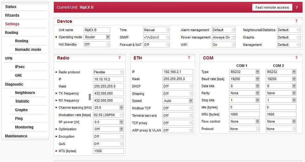
Parameters different from RipEX A:
Unit name: RipEX B
Radio IP: 10.10.10.2
Ethernet IP: 192.168.2.1
Open the Radio protocol details:
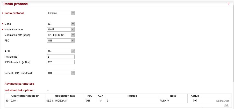
Radio protocol: Flexible
Mode: CE
Modulation type: QAM
Modulation rate: D8PSK
FEC: Off
ACK: On
Retries: 3
Default modulation rate is D8PSK (without FEC). Open the Advanced parameters “Individual link options” section and “Add” a new line.
Counterpart Radio IP: 10.10.10.1
Modulation rate: 16DEQAM
FEC: Off
ACK: On
Retries: 3
Note: RipEX A
RipEX B will always use D8PSK modulation rate (without FEC) when communicating with RipEX C (10.10.10.3) and for all broadcast data thanks to default/basic modulation. Modulation back to RipEX A is set to the higher 16DEQAM modulation.
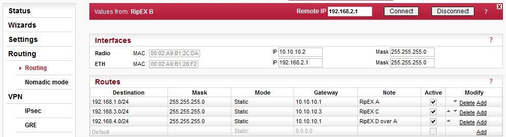
Routing rules:
192.168.1.0/24 via 10.10.10.1 (direct link)
192.168.3.0/24 via 10.10.10.3 (direct link)
192.168.4.0/24 via 10.10.10.1 (RipEX A is used as a repeater)
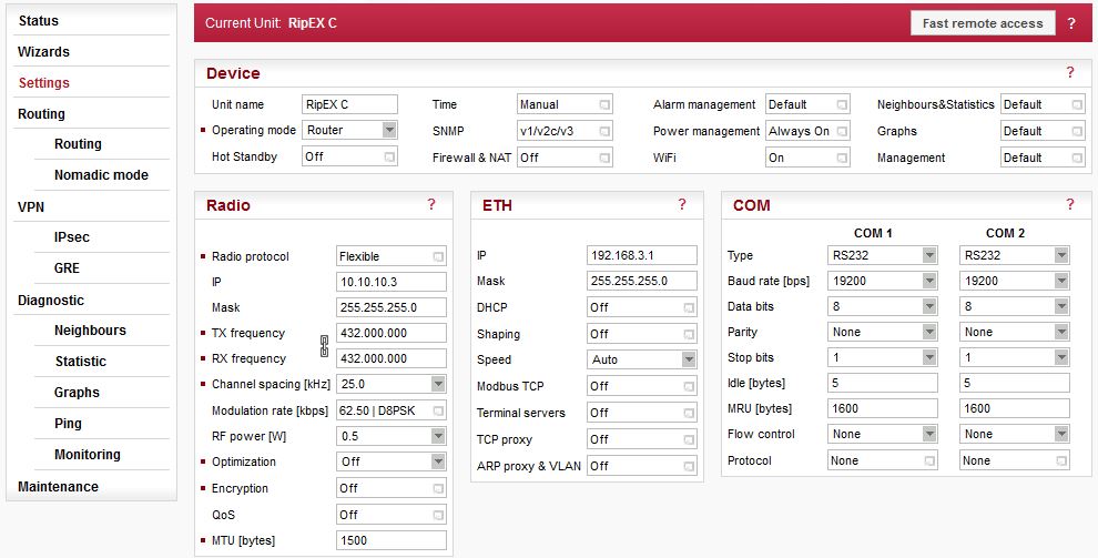
Parameters different from RipEX A:
Unit name: RipEX C
Radio IP: 10.10.10.3
Ethernet IP: 192.168.3.1
Open the Radio protocol details:
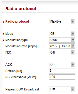
Radio protocol: Flexible
Mode: CE
Modulation type: QAM
Modulation rate: D8PSK
FEC: Off
ACK: On
Retries: 3
Default modulation rate is D8PSK (without FEC) and there is no special individual link option configured.
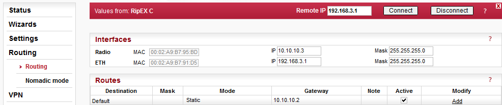
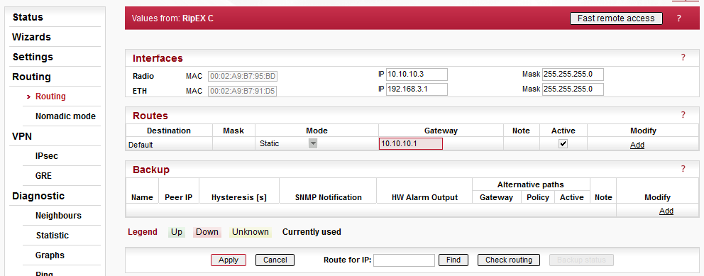
RipEX C only configures a default route via RipEX B (10.10.10.2).

Parameters different from RipEX A:
Unit name: RipEX D
Radio IP: 10.10.10.4
Ethernet IP: 192.168.4.1
Open the Radio protocol details:
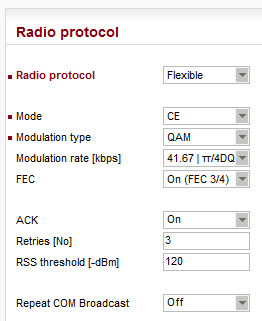
Radio protocol: Flexible
Mode: CE
Modulation type: QAM
Modulation rate: π/4DQPSK
FEC: On
ACK: On
Retries: 3
Default modulation rate is π/4DQPSK (with FEC) and there is no special individual link option configured.
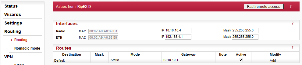
RipEX D configures only a default route via RipEX A (10.10.10.3).
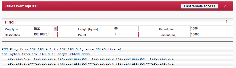
One RSS ping can display all required information. Issue the RSS Ping from RipEX D (10.10.10.4) to RipEX C (10.10.10.3).
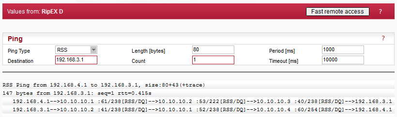
The RSS ping output shows 3 radio hops in each direction, in total 6 radio hops. But the modulation rate is not visible here. Configure the Monitoring with correct parameters and Start it.
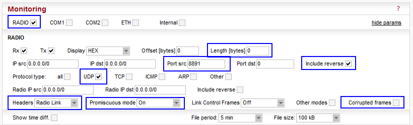
Parameters:
Interface: Radio
Length: 0 Bytes
Port src: 8891, Include reverse checked
Protocol type: UDP
Headers: Radio Link
Promiscuous mode: On
Corrupted frames: unchecked
This configuration will monitor the Radio interface, displaying the required headers but no data (the payload is not important for this test). The RSS ping operates via UDP port 8891 and it’s not desired to display any corrupted packets. The promiscuous mode must be enabled so the monitoring displays all data within radio coverage; not only data destined to this radio (e.g. traffic from RipEX A to RipEX B).
Run the Monitoring by pressing the “Start” button and afterwards, re-run the RSS ping.
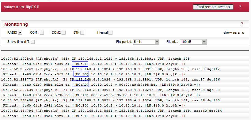
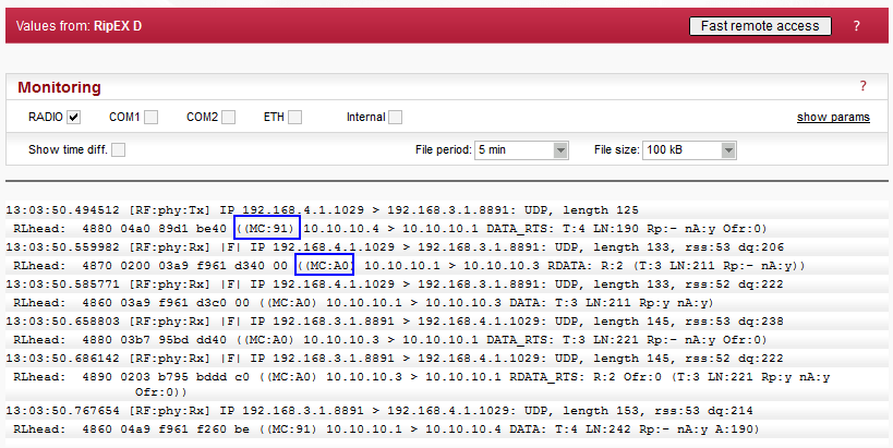
For each displayed packet, there is information about Modulation rate and FEC. See the highlighted values “MC:XY”.
TX Modulation and Coding ((MC:00)) explanation:
- [7..4] Modulation Select Nibble
0x0 = 2-CPFSK (default)
0x1 = 4-CPFSK
0x8 = DPSK
0x9 = π/4DQPSK
0xA = D8PSK
0xB = 16-DEQAM
- [3..0] Coding Select Nibble
0x0 = FEC Off (default)
0x1 = FEC On
In our example, there are three values:
MC:91 – π/4DQPSK & FEC On, used for the Radio link between RipEX D and RipEX A
MC:B0 – 16-DEQAM & FEC Off, used for the Radio link between RipEX A and RipEX B
MC:A0 – D8PSK & FEC Off, used for the Radio link between RipEX B and RipEX C
The direction back is the same in our example. In Flexible mode, it is even possible to define different settings for different directions of one radio link. This is not possible in BDP.
Run RSS ping from another RipEX to any other and verify the behaviour in the Monitoring menu. You can check the same using any traffic, of course – e.g. run your application over the testing network.
Base Driven protocol is slightly different in the way it handles individual link options. In BDP, all communication is strictly controlled by the Base station and this Base station configures all modulation rates within the whole network. Individual remote units must comply with the Modulation type; ACK can be configured at each remote unit separately.
In Figure 2.18 you can see two Modulation rates for one Radio link between RipEX A and RipEX B. This is due to BDP behaviour. If the Base station is communicating with RipEX B, it uses 16DEQAM modulation rate. But if it communicates with RipEX C, it uses D8PSK for the whole path (i.e. for those two Radio hops and the way back as well). It is NOT possible to configure it as in the Flexible mode.
| Note | |
|---|---|
If there was another RipEX behind RipEX B (repeater), we could configure the communication via another Modulation rate, e.g. π/4DQPSK. And when communicating with this unit, the Radio hop between RipEX A and RipEX B will operate using this π/4DQPSK Modulation rate. |
Another difference is that all the communication goes over the Base station. Even if we had a direct Radio link between RipEX D and RipEX C, the communication must go over the Base station (RipEX A).
See the following configuration example of how to configure the same network as in Chapter 2.1., but using BDP.
| Important | |
|---|---|
Always set the basic/default modulation to the most robust option (i.e. the lowest modulation required in one BDP network). This modulation is used for all BDP overhead data so all the units within the network must receive such data correctly. User data traffic is sent based on “Remotes” table rules explained on the following pages. |
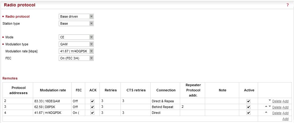
Open the Radio protocol details of RipEX A (Base) and change the configuration:
Radio protocol: Base driven
Station type: Base
The Individual link options submenu disappeared, but a very important submenu “Remotes” has appeared and can be configured. All remote units must be configured in this table, otherwise they will not be accessible. Configure all three remote units:
Protocol address: 2
Modulation rate: 16DEQAM
FEC: Off
ACK/CTS: Enabled (3, 3)
Connection: Direct & Repeater
Protocol address: 3
Modulation rate: D8PSK
FEC: Off
ACK: Enabled (3)
Connection: Behind Repeater (2)
Protocol address: 4
Modulation rate: π/4DQPSK
FEC: On
ACK/CTS: Enabled (3, 3)
Connection: Direct
| Note | |
|---|---|
Please see the details in BDP application notes. |
| Important | |
|---|---|
Configured modulation will be used for all the user data traffic between particular units. The overhead data are sent on the basic modulation (π/4DQPSK in our case). |
Different modulation rates are used for each remote station. If the Base communicates with Remote 3 (RipEX C, 10.10.10.3), it uses D8PSK for all radio links on its path (even for the link Base <-> RipEX2).
Important change must be done in the Routing menu as well.
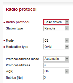
All the remote RipEX units have the same configuration. Change the Radio protocol to BDP and the station type to “remote”.
In the Routing menu, configure only the default route to 10.10.10.1, because all the communication is routed over the Base station.
The test will be the same – RSS ping from RipEX D to RipEX C.
In BDP, only the last hop is displayed in path to/from the Base unit. I.e. there are only two hops displayed for each direction, instead of three.
The first transmitted packet has the MC value 91 = π/4DQPSK with enabled FEC. The second displayed packet is from the Base station to RipEX B (repeater) and D8PSK modulation rate without FEC is used. A retransmitted packet from this repeater is also displayed using the same rate.
The RSS ping reply and a retransmitted packet both have the D8PSK rate as configured and the last hop uses π/4DQPSK again.
| Note | |
|---|---|
Please see the details in BDP application notes. |