In this chapter, we will explain the functionality of Base Driven Protocol. Some aspects were explained in Application notes Address planning and Channel access. See them before continuing this configuration example.
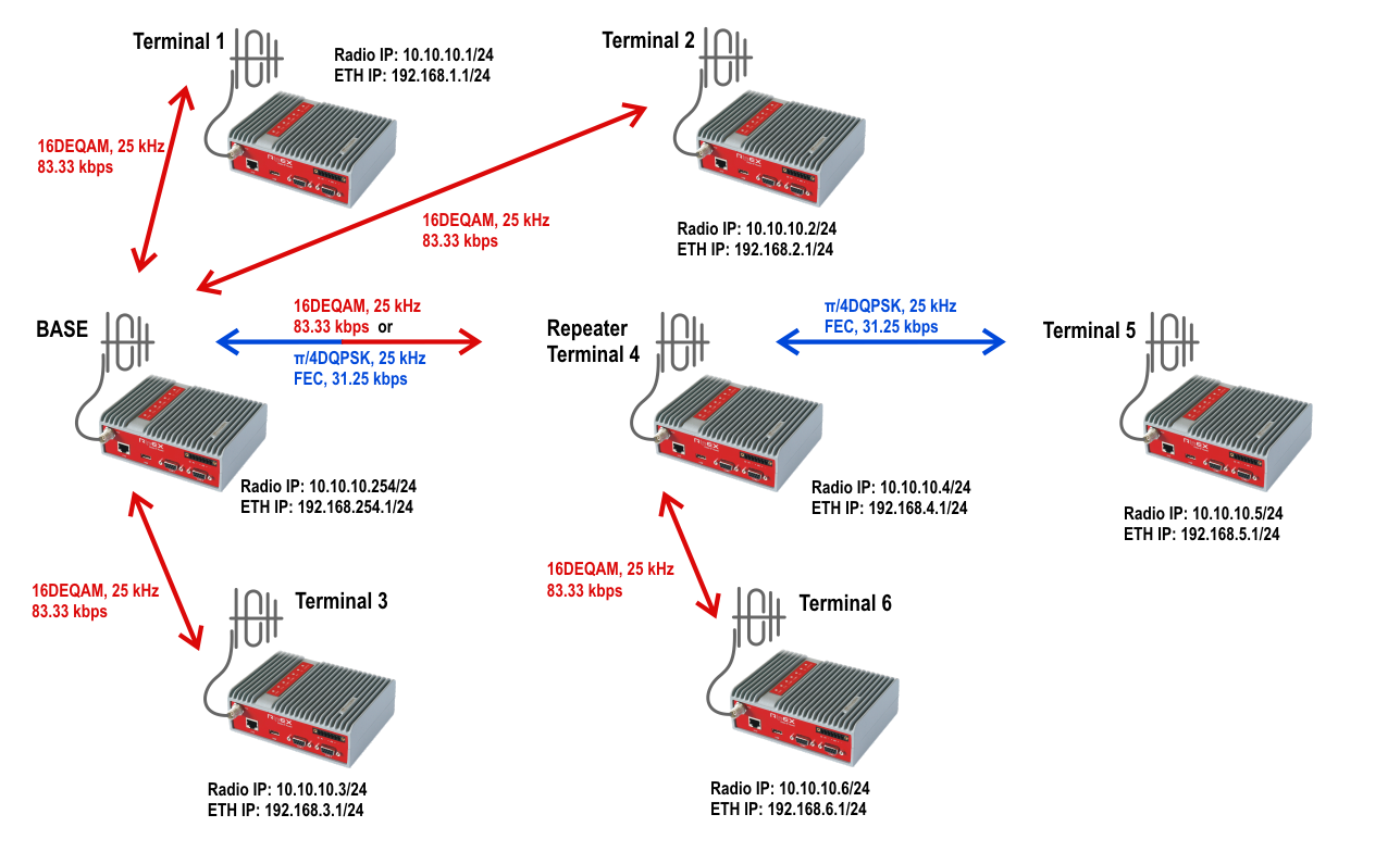
The topology consists of one Base station (there can only be one) and 6 terminals (remote RipEX units). One of these terminals serves as a repeater for other two.
From the configuration point of view, we have only two types of units.
Base
Remote
There is no “repeater” configuration in Terminal 4. The terminal itself is configured in the exact same way as Terminals 5 and 6. The communication is managed by the Base station which forwards data either directly or via this repeater.
Since the firmware 1.6, RipEX units can also be configured with various modulation rates for individual links. In this example, we configure the highest modulation rate for all links except the link to RipEX terminal 5 (e.g. because there is a bad signal quality). This link is set to use the π/4DQPSK modulation and has FEC enabled.
| Note | |
|---|---|
If the Base station communicates with Terminal 5, it uses the π/4DQPSK modulation even for the hop between the Base and Repeater, not only for the link between Repeater and Terminal 5. |
All units are configured with a Radio IP address within 10.10.10.0/24 subnet. The Ethernet subnets are different for each unit. Each RipEX has the Ethernet address equal to 192.168.x.1/24 where “x” the last digit of its Radio IP address (i.e. Protocol address).
There is no other special functionality configured in this example, such as Modbus TCP, ARP Proxy, TCP Proxy or Protocol server. The Base driven protocol (BDP) is suitable for transparent TCP traffic and thus, only the correct routing is required.
| Note | |
|---|---|
All features are configurable both in the Flexible and Base driven protocols; the Backup routes functionality is only available in the Flexible protocol. |
If more than one repeater is required for the remote unit reachability, the Flexible mode should be used or another RipEX unit connected “back-to-back” via switch is necessary creating another BDP network on its own frequency. There cannot be any radio overlap for several BDP networks (i.e. only one Base station can be in the radio coverage).
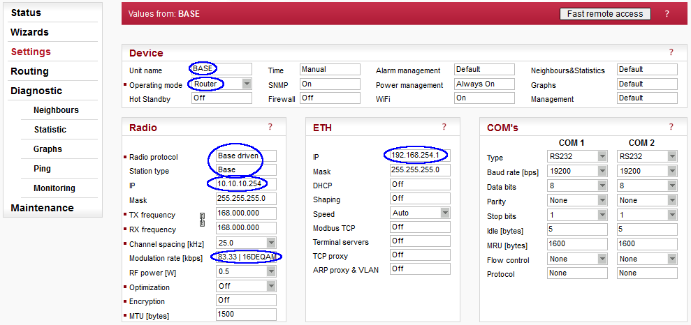
The Base station must be configured in the following way:
Name: BASE (no functionality influence)
Operating mode: Router
Radio protocol: Base driven
Station type: Base
Radio IP: 10.10.10.254/24
Ethernet IP: 192.168.254./1/24
Modulation rate: 16DEQAM
Once you open the Station type configuration, a detailed configuration for all remote units is available:
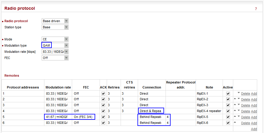
Modulation type is set to “QAM” which enables communication with terminals using any modulation within this type (16DEQAM, D8PSK, π/4DQPSK or DPSK).
In the “Remotes” table, the individual configuration for each Terminal must be done. Notice the 41.67 kbps modulation rate and enabled FEC used for Terminal 5 (bad condition simulation). Three terminals (1-3) are configured with a “Direct” connection. This means that all of them are reachable directly and not via repeater and are not used for repeating data for other terminals.
On contrary, Terminal 4 is set as “Direct & Repeater” so it forwards data for other terminals. In this example, it forwards data for terminals 5 and 6 (see the particular lines) – both terminals are configured with a “Behind Repeater” connection type and they use the repeater with a protocol address 4. There could be more repeaters so this number is important.
| Note | |
|---|---|
Three “basic” direct terminals (1, 2 and 3) can be configured on a single line – the Protocol addresses column would be set as “1 – 3”. Otherwise the configuration is the same. |
While this configuration is fully sufficient for Radio communication and any serial protocol communication (using the Radio IP addresses), we need to configure the Routing rules for all Ethernet subnets. Go to the Routing menu and configure the Base station.
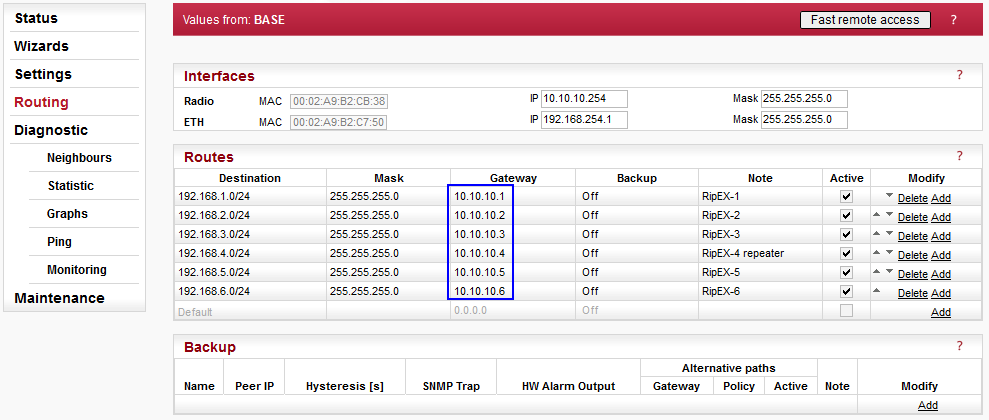
If you are familiar with a regular routing or/and routing in the Flexible mode, these rules might be a bit confusing. First four lines are OK, but in the Flexible mode, the routes for 192.168.5.0/24 and 192.168.6.0/24 would use the 10.10.10.4 Radio IP address as the gateway. This knowledge is already set by the “repeater” functionality within the BDP configuration. This results in a gateway configuration as they were also connected directly (gateways set to 10.10.10.5 and 10.10.10.6). But the BDP mechanism sends data for these networks via the configured repeater (10.10.10.4).
Once you finish this configuration, the Base station starts to communicate rapidly (see the TX LED diode on the unit). This is caused by the BDP mechanism. The Base station controls/manages all the communication within the network and checks the statuses of all remotes in very quick rounds (tens of milliseconds). If any DATA transmission is ready (any RipEX has packet in its queue for the Radio channel), it enables this communication in a very precise time slot minimizing any “waiting” period and utilizing the Radio channel for maximum. Due to this behaviour, there is always communication on the Radio channel even though there is no application data. In the Flexible mode, there is no data traffic in such situations, but collisions happen while in the BDP there is not a single collision on the Radio channel – i.e. the important jitter parameter is minimal (important for many TCP applications).
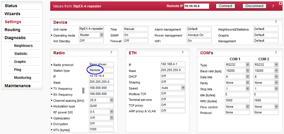
All other RipEX units must be configured following the IP addresses depicted in the topology diagram and the Station type must be “Remote”. Open this menu and configure the details:
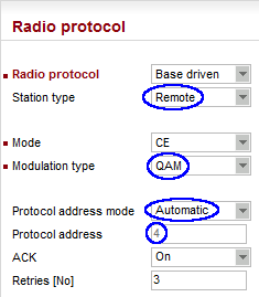
Terminal stations are not set with a particular Modulation, but only with a “type”. The exact modulation is set in the Base station. The Protocol address mode can be either “manual” or “automatic”. If the automatic method is set, the Protocol address is set to the last Radio IP digit (i.e. 10.10.10.4 -> 4).
The last step is to configure the static route back to the Base station’s Ethernet subnet.
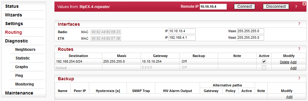
The only rule required is to the Base station. If the communication among any Ethernet subnets of any Remote RipEX units is necessary, add other static routes – all rules must use the same gateway 10.10.10.254 (Base), because complete communication goes over the Base station and not directly among individual Remote units.
Remote Stations Configuration
As already mentioned, the configuration is completely the same for all Remote stations, no matter if it is or it is not a repeater. Save the Repeater configuration into the file and upload it to other remote units. Only remember to change the Radio and Ethernet IP addresses! The rest of the configuration parameters are the same.