Link manager is a mechanism providing switching of several pre-configured alternative links (alternative static routes). Link switch is triggered in case of the active link failure. Link failure can be detected passively – by checking link interface physical status (see Watched interface parameter) and actively by ICMP ping (see Link testing parameter).
Link testing is active on currently active link and all higher priority links (to detect when they are available again). Lower priority links can also be tested (see Test backup link parameter). When the current link fails, link manager switches to the next functional lower priority link. If the link is not being checked (Test backup link parameter is disabled), it is assumed to be functional. Routing rules are updated automatically on link switchover.
IPsec tunnels can be bound to particular links via Peer ID parameter. In such a case the individual IPsec tunnel is activated/deactivated together with the respective link. It is automatically switched back to the higher priority link once it is restored.
See more details and all parameters explained in the User manual.
The application note will show you several examples using the Link management features.
All the examples can be applied both to RipEX2 and M!DGE3 with just slight differences, such as a cellular interface is the “MAIN” in M!DGE3, whereas in RipEX2 it is “EXT”. In RipEX2 you can also utilize a “Radio” interface which cannot be set in M!DGE3.
All examples utilize M!DGE3 cellular routers, because using Link management is more frequent in cellular devices than in radio modems.
The 1st example is not really used frequently, but can demonstrate nicely the main purpose of link priorities local management . You can also imagine private APN instead of public “internet” APN if it suits you better.
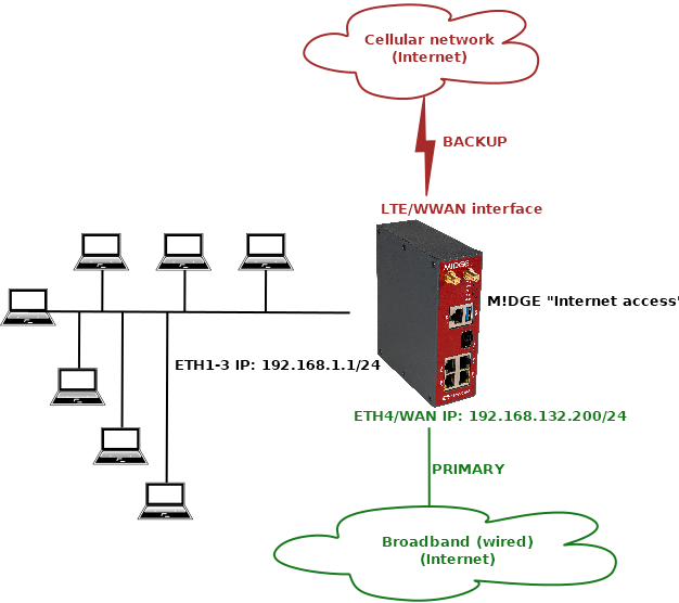
The scenario explains using the ETH4 port as a primary WAN link and having LTE (WWAN) only as a backup in case of primary WAN failure. This situation can be beneficial if WAN speed is in hundreds of Mbit/s, but the speed of 2G/3G/4G is lower, shared among other users within the BTS coverage etc.
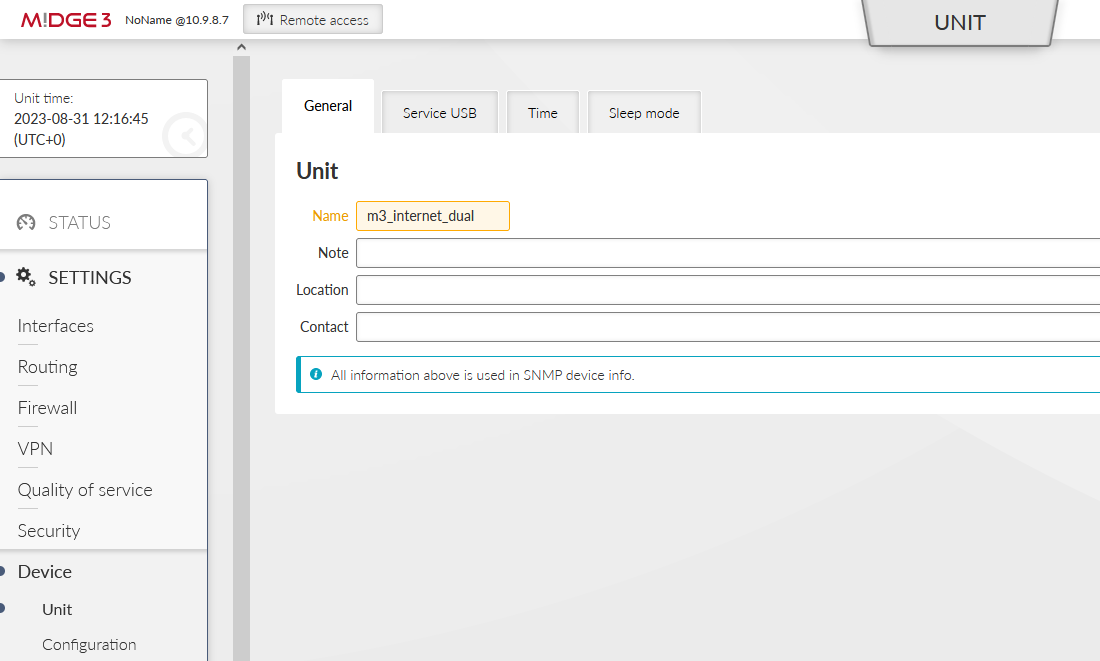
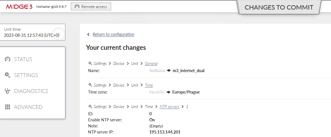
This scenario starts with a unit in factory setup. Login to the unit and go to the SETTINGS > Device > Unit menu and choose appropriate Unit name – in our example, it is “m3_internet_dual”.
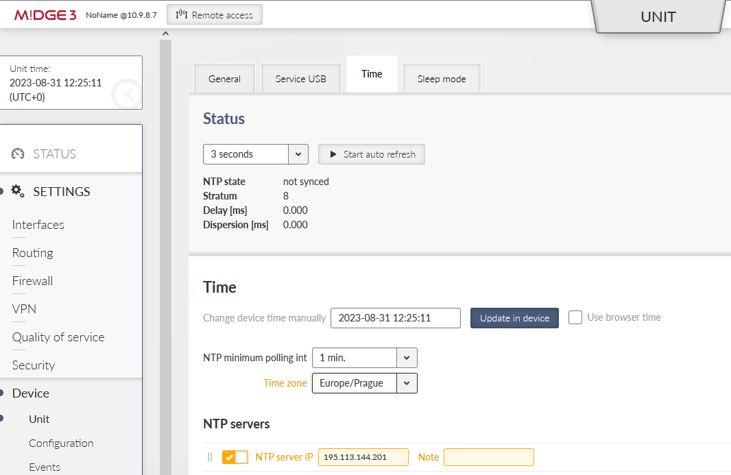
Configuring the NTP time synchronization is recommended. The unit has a correct time and eventual debugging is always easier, go to the SETTINGS > Device > Unit > Time menu.
Set a correct Time zone and add at least one NTP server IP address which is accessible within your APN.
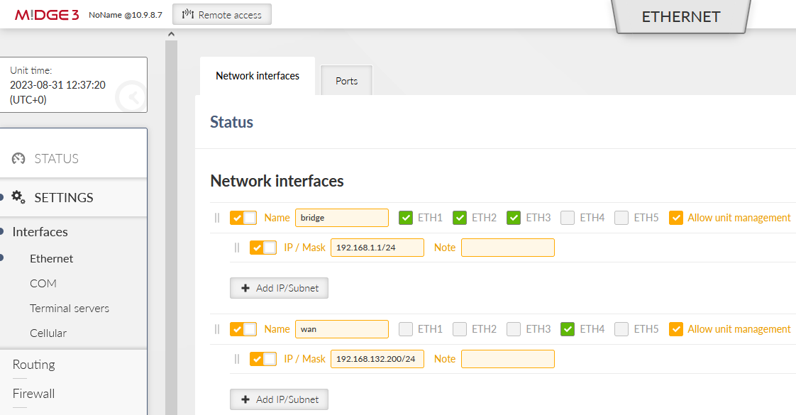
Go to the SETTINGS > Interfaces > Ethernet menu and configure correct IP addresses.
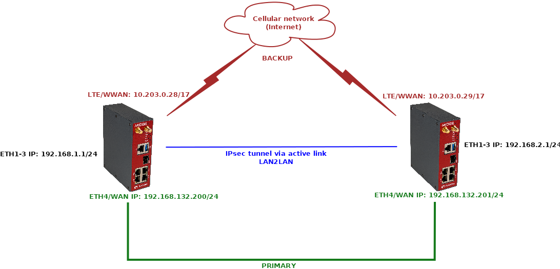
Set ETH1-3 Network interface IP to 192.168.1.1/24. The ETH4 is our WAN with 192.168.132.200/24 and we name it “wan”.
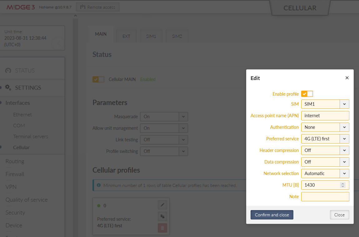
Go to the SETTINGS > Interfaces > Cellular menu and configure your cellular profile to suit your SIM card and provider’s setup. In our case, we just set ‘internet’ as our APN. There is no need to configure “Link testing” now (we do it later in the Link management itself).
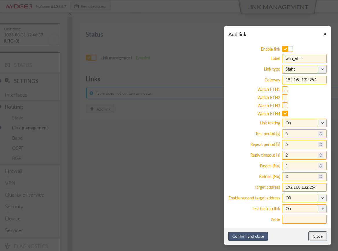
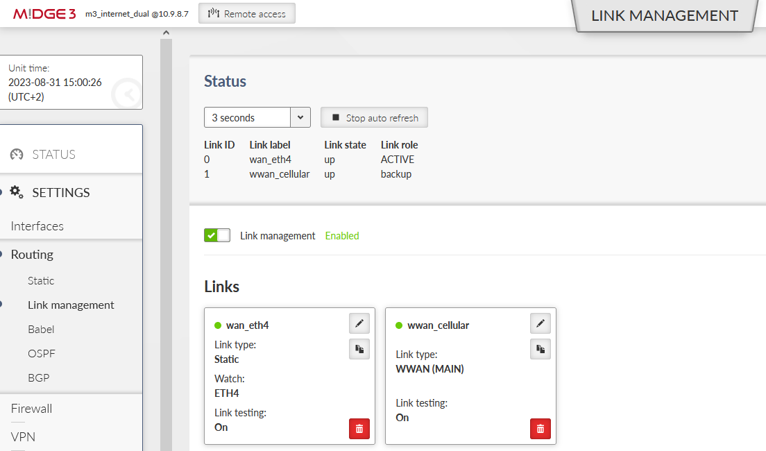
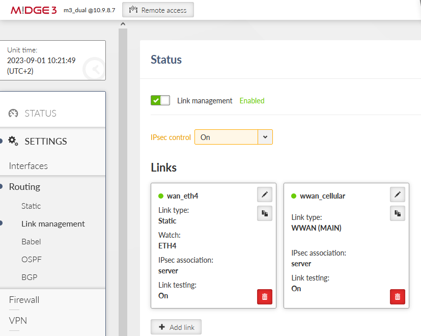
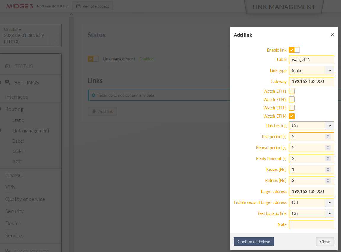
Go to the SETTINGS > Routing > Link management menu and enable this feature. Click on the “Add link” button and configure the WAN/ETH4 link.
Label: “wan_eth4”
Link type: “static”
Gateway: 192.168.132.254
This “broadband” connection can be simulated by any other device with 192.168.132.254 IP, or set it to match your actual LAN Internet setup.
Watch ETH4 – so that the link goes up/down based on ETH4 physical status (cable connected/disconnected).
Enable Link testing
Target address – we will ping 192.168.132.254 Gateway IP – if the IP is not accessible three times in a row, the link is considered down. Once the ping succeeds, the link becomes up again.
Choose required timing – we set short intervals due to high Ethernet speed and requirement for fast reaction on link changes
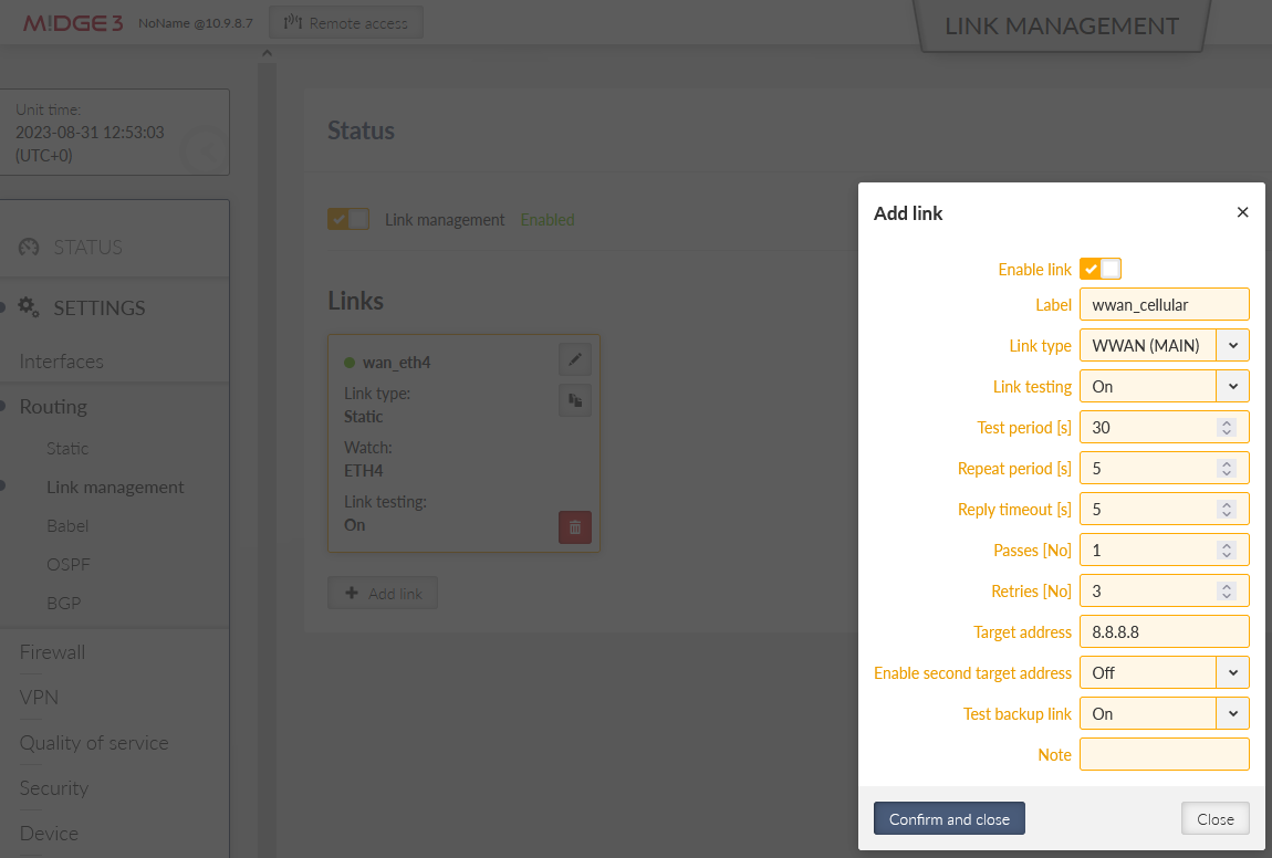
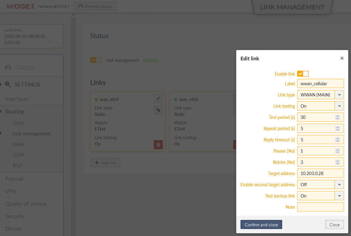
Configure 2nd link via the cellular WWAN (MAIN) interface:
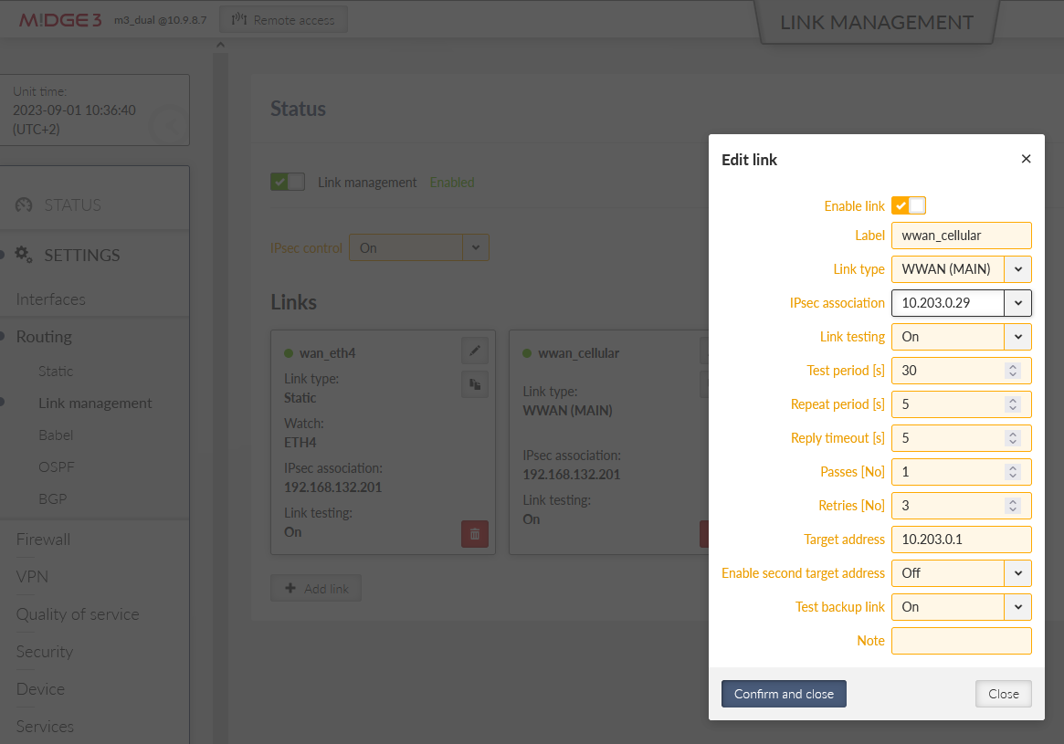
Label: “wwan_cellular”
Link type: “WWAN (MAIN)”
Link testing: On
We ping the Google server IP 8.8.8.8 in longer intervals
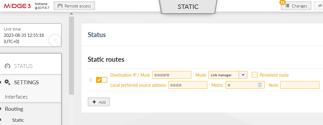
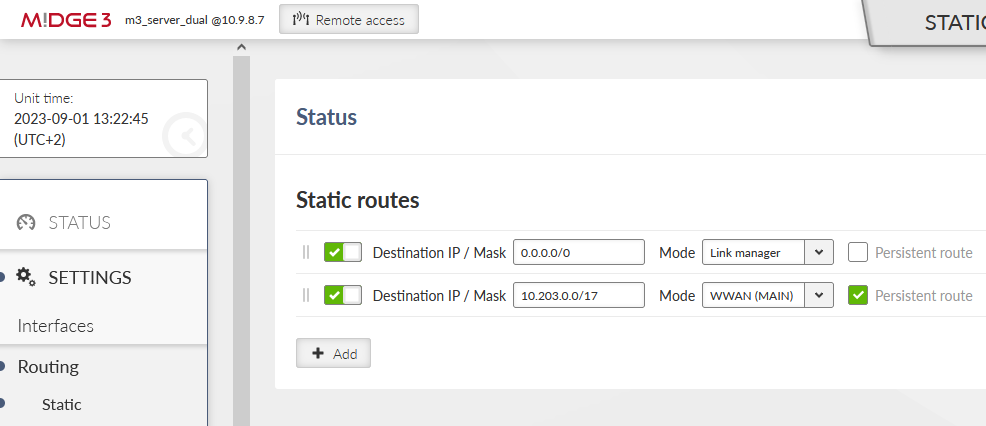
Go to the SETTINGS > Routing > Static menu and add 0.0.0.0/0 default gateway via “link manager”.
Go to the “Changes” basket, verify the changes and if all is OK, click on the “Send configuration” button to store the configuration in the unit.
| Note | |
|---|---|
When connecting a device to the ETH1-ETH3 bridge, it can communicate locally with the M!DGE3 but cannot access the Internet via the “wan” interface without manual configuration. While cellular connections have masquerading enabled by default, the Ethernet WAN requires you to manually add a Source NAT rule. This rule ensures that outgoing packets use the router’s WAN IP (192.168.132.200) instead of the original LAN IP (192.168.1.0/24). Without this translation, external targets or intermediate routers would be unable to route replies back to your device. |
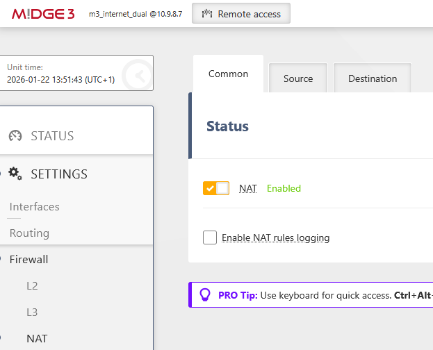
Enable NAT within SETTINGS > Firewall > NAT menu.
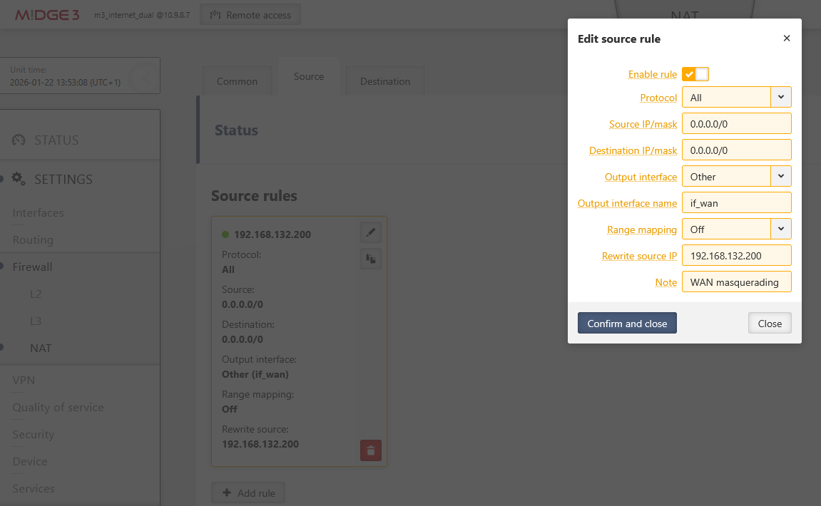
Go to the Source tab and one rule:
Output interface: “if_wan”
Rewrite source IP: 192.168.132.200
Optionally, add any “Note”
Test description
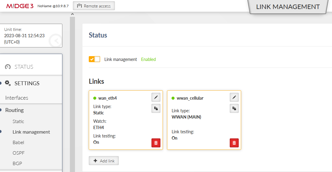
Go to the SETTINGS > Routing > Link management and open the Status menu. Click on the “Start auto refresh” button and see the states of configured links.
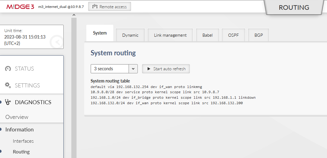
If you go to the DIAGNOSTICS – Information – Routing menu, you can check the System routing, i.e., the default 0.0.0.0/0 route is via 192.168.132.254 (or via cellular if a backup link is used).
The Link management tab has the same output as from its Settings menu.
You can also check the Monitoring menu – check the ETH4 and WWAN (MAIN) interfaces to see data being sent/received.
To simulate issues:
Disconnect and connect ETH cable from ETH4 port
Disconnect and connect the Gateway device (192.168.132.254) so that M!DGE3 ETH4 port is “up”, but the Link testing fails.
You can detach the cellular antenna(s) to simulate cellular issues as well.
Very often, encrypted communication is a must, or regular LANtoLAN traffic is just simply discarded in operator’s network, or even in your broadband connection.
IPsec VPN tunnel is suitable to solve the security/encryption and also LANtoLAN communication.
Note: Due to routing purposes, GRE L2/L3 are frequently used together with IPsec.
Configuration steps start after the Example 1.1 is completed.
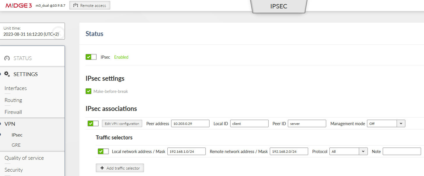
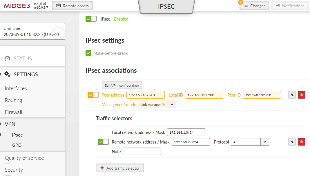
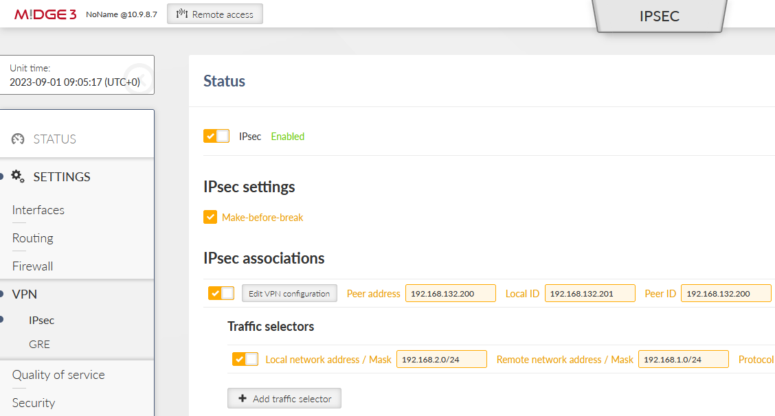
Go to the SETTINGS > VPN > IPsec menu and enable it. Add a new VPN configuration. Configure it to suit the opposite site. We suggest multiple parameters
Enable both Make-before-break and MOBIKE for faster and more reliable tunnel switching
Enable DPD detection to detect IPsec tunnel failures
Set the Start state to “Start” – so this M!DGE3 initiates the IPsec connection – keep in mind the opposite site (Peer) should be set to “Passive” state (waiting for incoming connections).
Keep the “Management mode” to “Off” – this is a special parameter for our Link management, but not yet configured for this example.
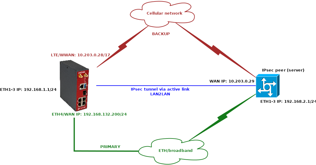
Possible IPsec setup overview:
Note: The Unit name is changed to “m3_dual”.
Test description
If you have both Links functional and you can reach the IPsec Peer IP, you can do the same tests as in the previous example, but now including the IPsec status check within the SETTINGS > VPN > IPsec menu and its Status.
You can also try to ping between laptops connected to both ends of IPsec tunnel during changing the active link.
Sometimes, we can see that the server also has two WAN IP addresses, each accessible via different Link. If we kept the same setup as above, we would not be able to connect to one of the IP addresses, because IPsec provides only one Peer IP address.
To solve this situation, we can use Link management to control what Peer IP (and even other IPsec parameters) to use via various links.
We cannot define two same IPsec tunnels differing only in Peer IP. Once there are some overlaps in traffic selectors, it cannot be saved, because that would cause networking issues.
In the following example, we
Define two IPsec tunnels with different Peer IPs
One will be set as “Master” and will be configured with proper Traffic selectors
One will be set as “Slave” and will become active only if the primary Link fails and will use the same Traffic selectors as the Master tunnel
The IPsec server will have two different IPs for its WAN
We utilize another M!DGE3 to demonstrate this example – i.e., we’ll configure two M!DGE3 units in point-to-point scenario. One connection will be via Ethernet; one connection via private APN (WWAN).
Most of the configuration is already done within the previous chapters (1.1 and 1.2) so we just edit the configuration of the unit on the left side of the diagram, the one with 10.203.0.28 IP on its WWAN and 192.168.132.200 on its ETH4/WAN. Afterwards, we need to do the complete setup of the 2nd unit.
Go to the SETTINGS > Routing > Link management and enable “IPsec control” option.
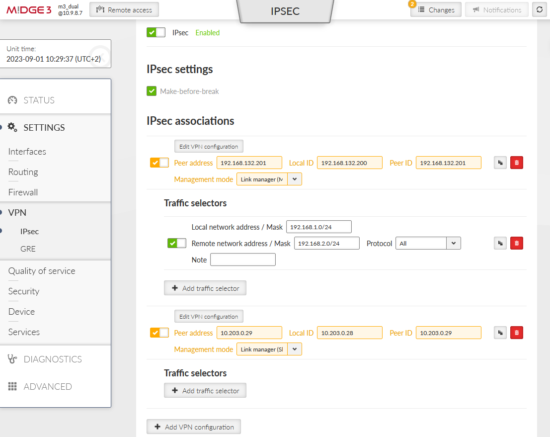
Go to the SETTINGS > VPN > IPsec menu and edit the tunnel created in the previous example – set the “Management mode” to “Link manager (Master)”. Set the “Peer address” to primary 192.168.132.201, “Local ID” to 192.168.132.200 and “Peer ID” to 192.168.132.201.
Copy the current tunnel using the “Copy” button and edit it.
Change the “Peer address” to 10.203.0.29
Change the “Management mode” to “Link manager (Slave)”
Set the Local ID to 10.203.0.28
Set the Peer ID to 10.203.0.29
Delete its Traffic selectors
Complete IPsec configuration:
Go back to the SETTINGS > Routing > Link management menu and edit the “wwan_cellular” link’s IPsec association to “10.203.0.29” so it uses the backup IPsec tunnel.
Once within this page, edit the Gateway and Target address of the primary “wan_eth4” link to 192.168.132.201 (opposite unit’s IP address).
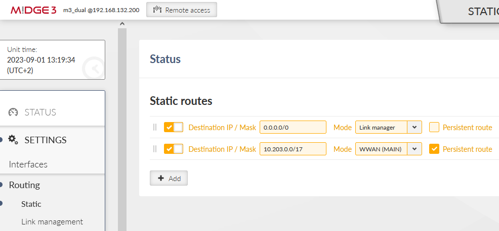
The last required change must be done in the SETTINGS > Routing > Static menu. We need to define additional route so that at least the opposite M!DGE3’s WWAN IP is always routed via WWAN (MAIN), or we can add the whole APN subnet (in our case, we have a private APN subnet 10.203.0.0/17).
Without such a rule, Link test via WWAN (MAIN) while operating over primary WAN/ETH4 would always fail.
Apply the changes.
We need to configure the 2nd M!DGE3 unit. You can either download the configuration file of the 1st M!DGE3 unit and upload the file into this one. Once uploaded, edit all the required parameters. But we do it step-by-step from the factory settings.
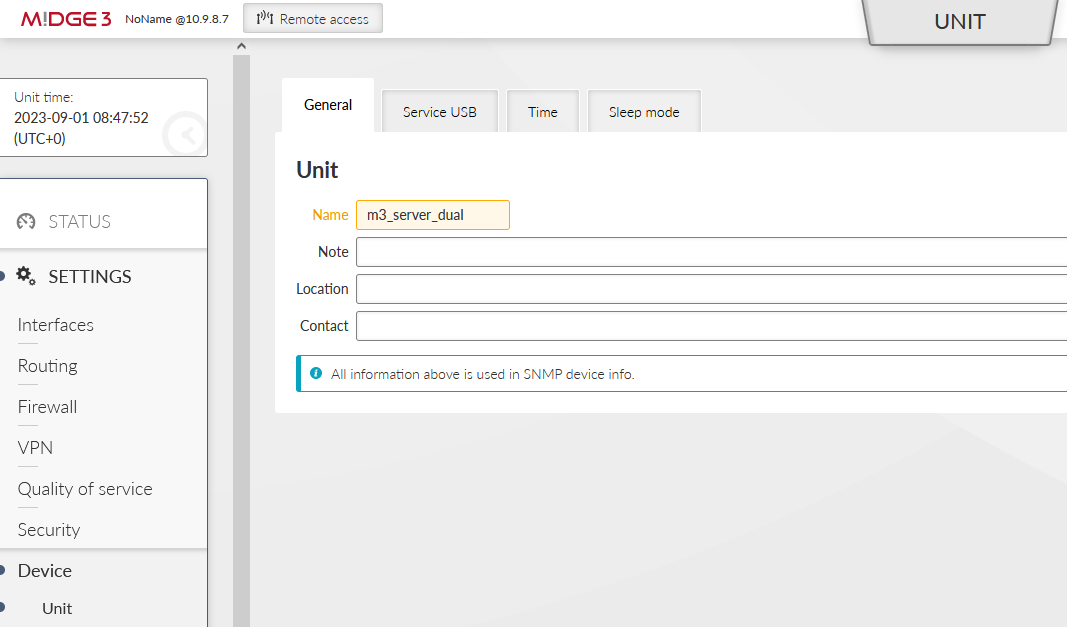
Change the Unit’s name in the SETTINGS > Device > Unit menu to “m3_server_dual”. Configure the NTP time synchronization as well, if applicable.
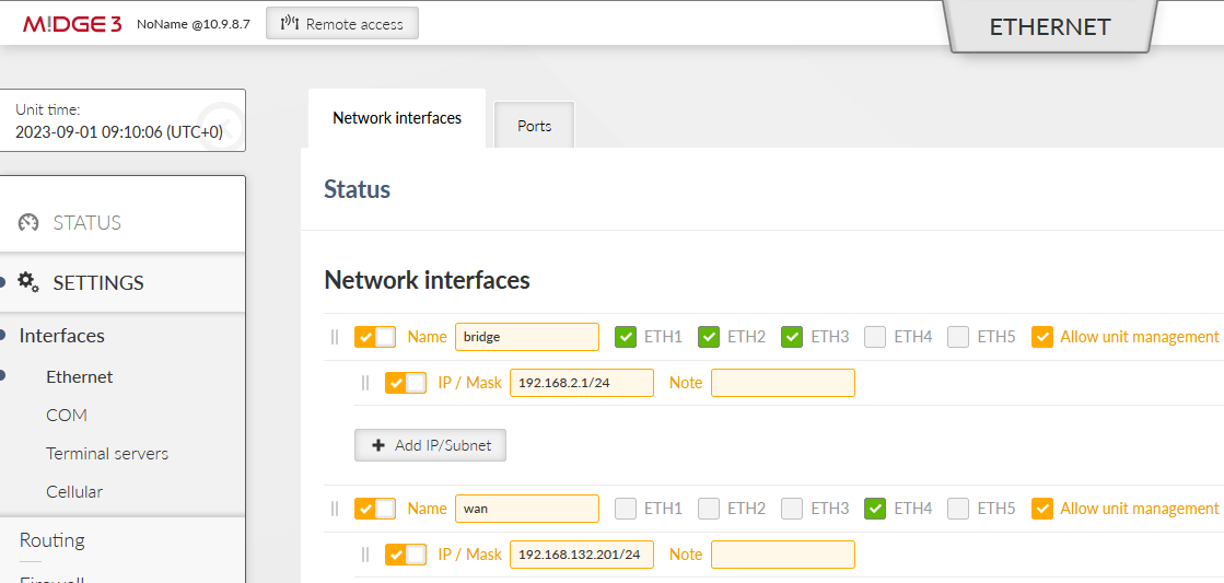
Go to the SETTINGS > Interfaces > Ethernet menu. Set the correct 192.168.2.1/24 IP address for the “bridge” interface and create “wan” interface with 192.168.132.201/24 IP address and mask, set on ETH4.
Go to the SETTINGS > Interfaces > Cellular menu and enable the interface. Configure the APN to suit your operator’s network.
Go to the SETTINGS > Routing > Link management menu. Enable it and configure two links. We configure and name them similarly to the “client” M!DGE3 unit.
Set values other than default for the primary link:
Label to “wan_eth4”
Gateway “192.168.132.200”
Watch ETH4
Enable Link testing and decrease timing
Target address “192.168.132.200”
Create the backup link and set
Label to “wwan_cellular”
Link type to “WWAN (MAIN)”
Enable Link testing and edit the timing
Target address to 10.203.0.28
Go to the SETTINGS > Routing > Static menu. Set the default route via Link manager and add the private APN subnet routing via WWAN (MAIN).
Go to the SETTINGS > VPN > IPsec menu and enable it. Enable “Make-before-break” and add a VPN configuration.
The tunnel setup, other than factory settings, or important:
Start state: passive
MOBIKE: On
DPD: On (action: Hold)
Passphrase: racom
Peer address: 192.168.132.200
Local ID: 192.168.132.201
Peer ID: 192.168.132.200
Add the Traffic selectors for local 192.168.2.0/24 and remote 192.168.1.0/24 subnets.
Go to the SETTINGS > Routing > Link management menu and enable IPsec control option. Go back to IPsec configuration page and set the 1st IPsec association mode to “Master”.
Copy the current tunnel using the “Copy” button and edit it.
Change the “Peer address” to 10.203.0.28
Change the “Management mode” to “Link manager (Slave)”
Set the Local ID to 10.203.0.29
Set the Peer ID to 10.203.0.28
Delete its Traffic selectors
Go back to the Link management configuration and set the IPsec association of “wwan_cellular” link to “10.203.0.28”.
Apply all the changes.
Test description
Do the similar tests like in previous examples
Disconnect ETH cable(s)
Disconnect LTE antenna(s)
Change Link manager’s timings
Run LAN2LAN ICMP tests while switching links
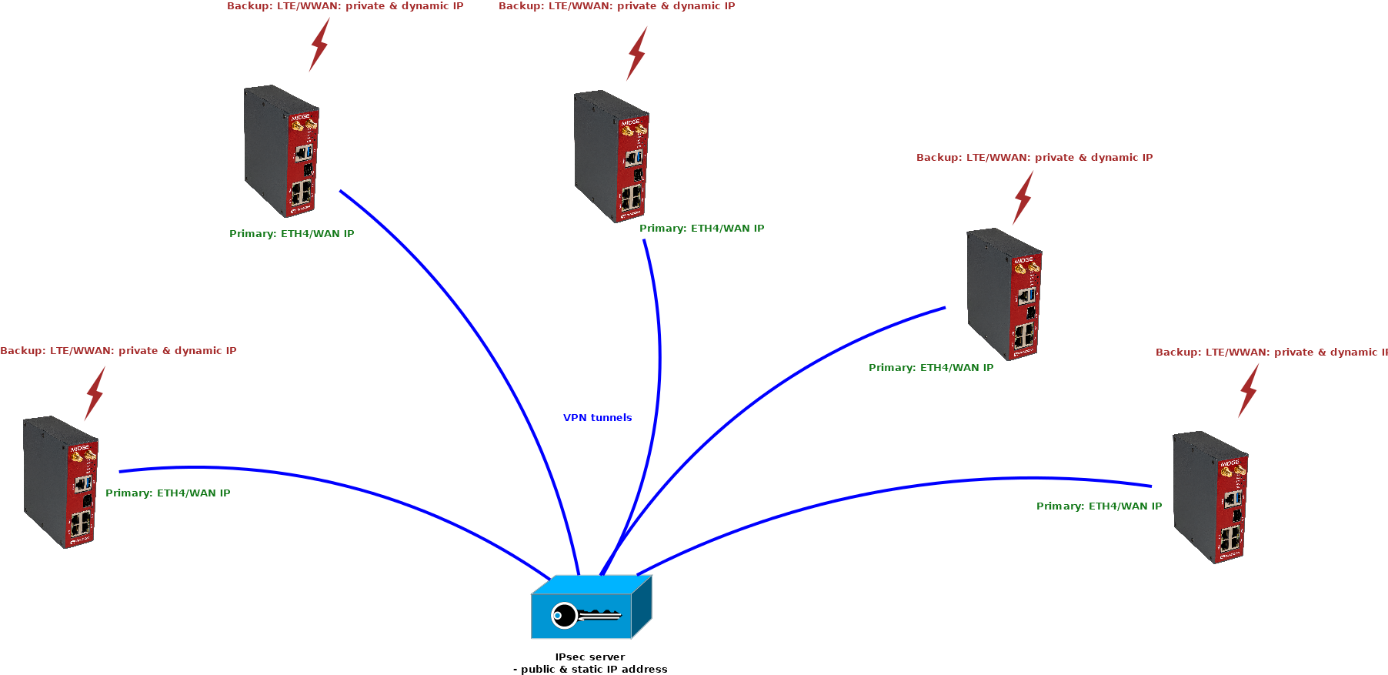
By combining previous examples, you can achieve multiple goals/topologies. One of possible and typical solutions is that you have a dedicated IPsec server with a static and public IP address (e.g. CISCO router). This device has its own redundancy options regardless of M!DGE3 remote units.
Each our M!DGE3 unit has two WAN interfaces, as described
Primary WAN via ETH4
Backup WAN via cellular WWAN (MAIN)
This priority is being controlled by Link manager in each M!DGE3 regardless anything else.
Due to the fact the server has one public IP address, IPsec tunnels do not need to be controlled by the Link manager. The Link manager ensures only routing via correct WAN link.
You can achieve similar topology:
If configured correctly, you can also achieve LAN2LAN communication among M!DGE3 units, but through the central IPsec server. You just need to set the Traffic selectors correctly. Number of such lines can be high with increasing number of remote units and possible subnets.
OpenVPN is going to be implemented in M!DGE3/RipEX2 units as a better solution for P2MP scenarios.
