There are two basic scenarios:
Terminal devices are connected to Ethernet interface
Terminal devices are connected to COM port
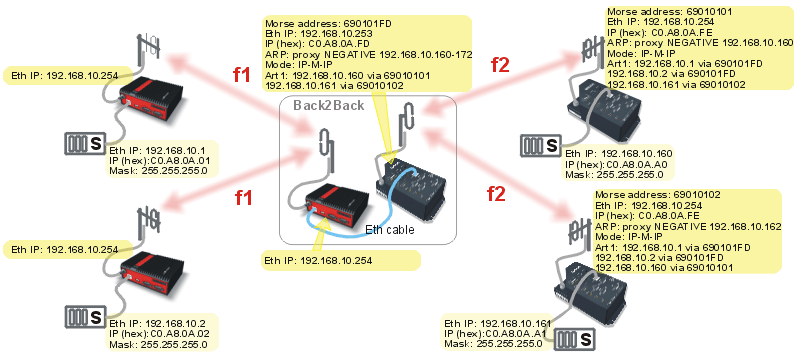
If terminal devices are connected over Ethernet, the border RipEX and MRxxx should also be interconnected by an Ethernet cable. The IP addresses of all devices in the network should belong to a single LAN.
The picture shows MORSE network settings; note the use of Proxy ARP in IP-M-IP mode.
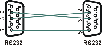
The COM port of the border RipEX and the RS232 of the border MRxxx are connected with a crosslink serial cable, see Fig. 1.2, “Crosslink serial cable”.
The COM port protocol at the border MRxxx must be the same as protocol used by the other MORSE devices in the network. In some special cases, the ASYNC LINK protocol can be used for the border interconnection.
If the Master is located on the side of the MRxxx, the border MRxxx should be set to Slave. Depending on the SCC interface used the MRxxx should use Multiaddressing with addresses of all the Slave units on the RipEX network.
If the Master is located on the side of the RipEX, the border MRxxx is set like it was connected to the Master and the Node of the connected SCC interface has to correspond to the Master’s address.
There are two basic scenarios:
Terminal devices are connected over Ethernet
Terminal devices are connected over COM interface
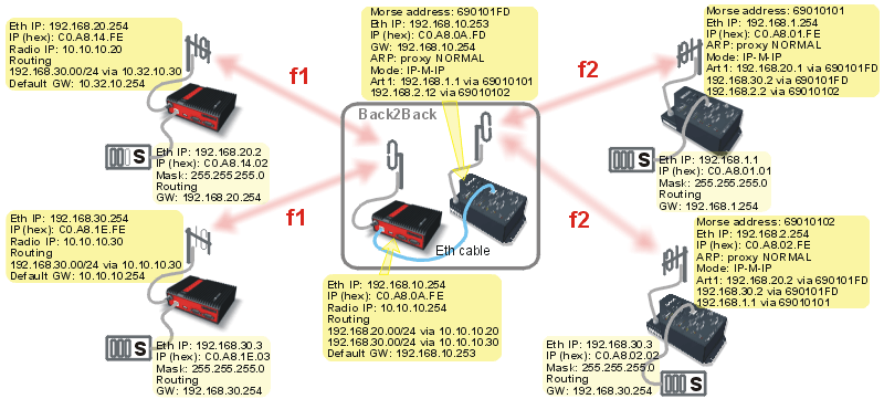
In this scenario the border RipEX and MRxxx should be interconnected with an Ethernet cable.
Routing in both parts of the network should be set up so that communication between them is channeled over the border modems. It is recommended that terminal devices in the two parts of the network are located on separate LAN’s.
The picture shows MORSE network settings.
A MORSE network can only be expanded with RipEX modems if the application protocol is supported both by MORSE and RipEX, or if RipEX’s UNI protocol can be used instead. If you want to use protocols which are not implemented in RipEX by default, please consult RACOM’s technical support.
The COM port of the border RipEX and the RS232 of the border MRxxx are connected with crosslink serial cable, see Fig. 1.2, “Crosslink serial cable”.
If the Master is located in the MORSE part of the network, the border MRxxx should use Multiaddressing for addresses of all Slaves in the RipEX network. Protocol settings should reflect that. The border RipEX then should be set up as connected to the Master using the appropriate protocol (address translation using a mask or table, routing rules).
If the Master unit is located on the RipEX side of the network, rules for address translation should direct all the packets sent to Slave units of the MORSE network to the COM port connected to the border MRxxx. This COM port should then use an appropriate protocol in Slave mode. In the border RipEX the timeout for response from technology should be extended from 500 ms to several seconds (the response time will depend on the size of the MORSE network) – this parameter can only be set in CLI. On the MORSE side, the protocol should be set to Master.


