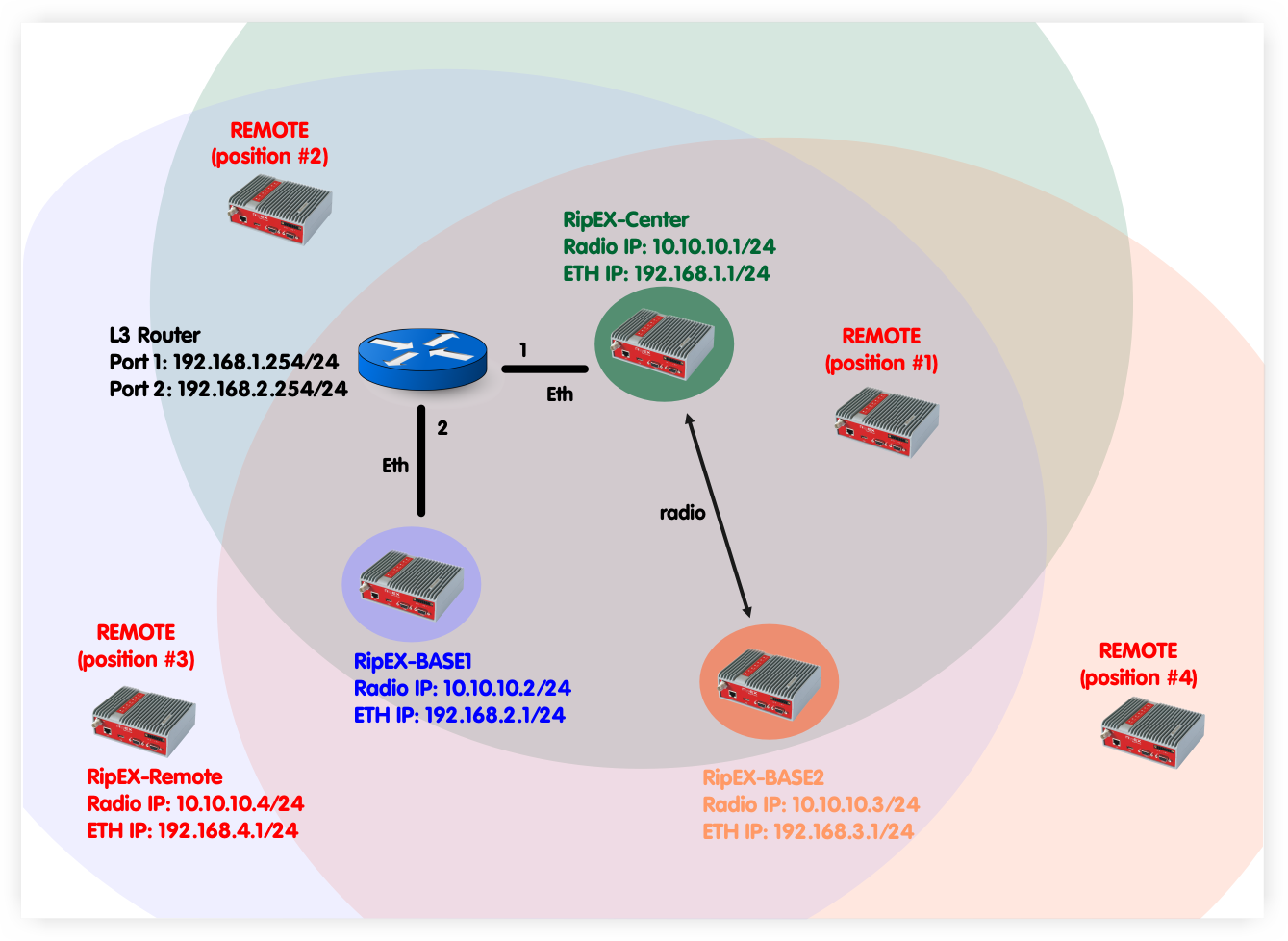
In this example, 4 RipEX units are used. RipEX-Center serves as a Center for the Nomadic mode functionality. Two units serve as Bases (RipEX-Base1 and RipEX-Base2). The fourth unit is called RipEX-Remote and serves as a Remote unit. This unit can be placed anywhere within the radio range of at least one RipEX Base (Center is also operating as a Base) and it dynamically creates connection with the best Base. There is no need to re-configure the Remote unit, the Nomadic mode handles the connectivity on its own.
NOTE:
The topology diagram depicts different Remote
unit positions, but it is actually one unit.
In the following chapter, individual RipEX units’ configuration will be explained and showed together with actual dynamic routing so no matter where the Remote RipEX is placed, it can always communicate with other units within the network.
Parameters:
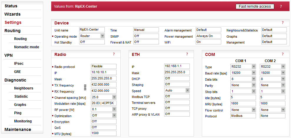
Unit name | RipEX-Center |
Operating mode | Router |
Radio protocol | Flexible (Nomadic mode is supported only in the Flexible protocol) |
Radio IP/Mask | 10.10.10.1/255.255.255.0 |
Frequency | 432.000.000 MHz (configure any frequency, but the same among all RipEX units – simplex or duplex scenarios are both possible) |
Channel spacing | 25 kHz (configure any spacing, but this must be the same for all units) |
Modulation rate | 20.83 | 4CPFSK (use the same “type” for all units, but otherwise, configure as preferred) |
RF power | 0.1 W (set the minimum possible RF power for tests using dummy loads on your desk – laboratory tests) |
ETH IP/Mask | 192.168.1.1/255.255.255.0 |
There is no special configuration within the Flexible Router mode required.
Parameters:
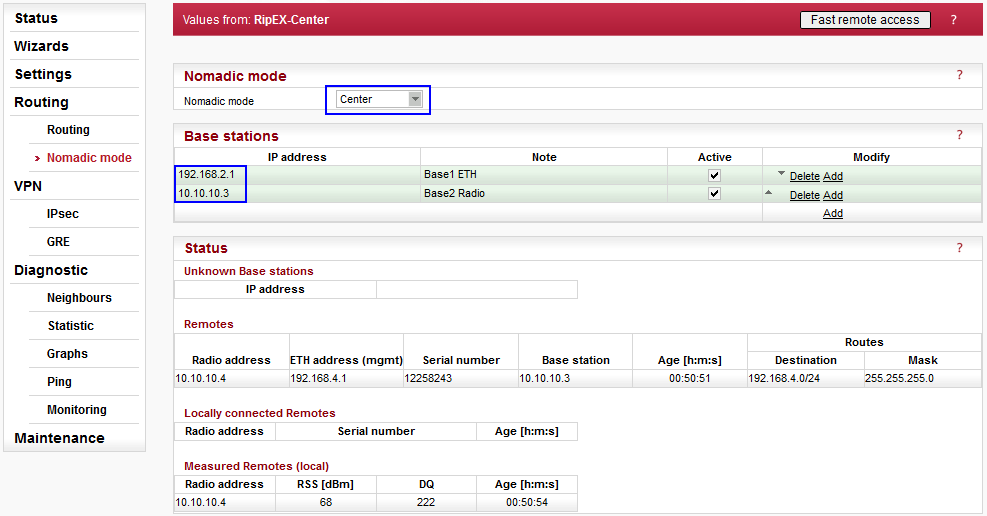
Nomadic mode | Center |
Base stations | 192.168.2.1, Base1 ETH, Active |
In this RipEX network, there must be only one central unit. The central unit communicates and controls the Nomadic functionality together with the two Base units. One Base is connected via Ethernet and one is connected over the Radio channel. The central unit also acts as a Base.
Once the central unit synchronizes with Base units and the Remote unit, the Status is displayed i.e. information about the connected Base and Remote units. See the details in Chapter 2.5.1.
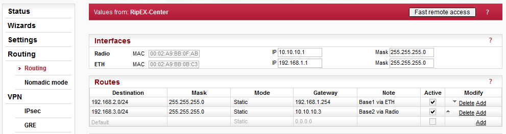
Within this example, two routes are set.
192.168.2.0/24 via 192.168.1.254, Mode: static
192.168.3.0/24 via 10.10.10.3, Mode: static
Both routes are required due to Base stations’ networks accessibility. The network of the Remote unit is not configured, because it is created dynamically upon the Remote unit current location. This route is displayed in the Nomadic mode menu.
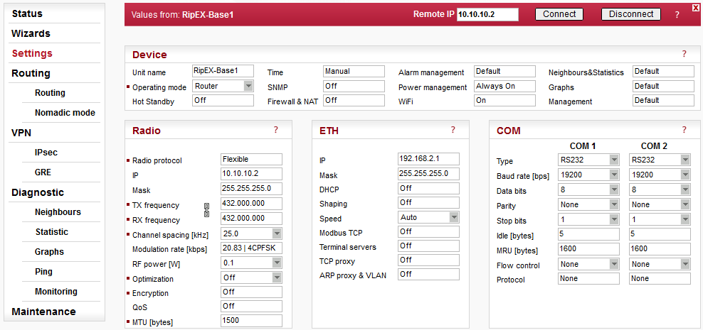
Only the different parameters compared to the central unit are explained below.
Parameters:
Unit name | RipEX-Base1 |
Radio IP/Mask | 10.10.10.2/255.255.255.0 |
ETH IP/Mask | 192.168.2.1/255.255.255.0 |
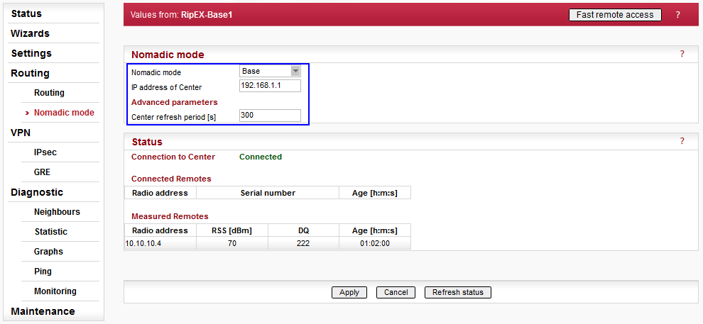
Parameters:
Nomadic mode | Base |
IP address of Center | 192.168.1.1 (RipEX-Center Ethernet IP address – the communication is operated via Ethernet) |
Advanced parameters:
Center refresh period [s] | 300 |
The Status menu is described in Chapter 2.5.1 once the complete network is configured.
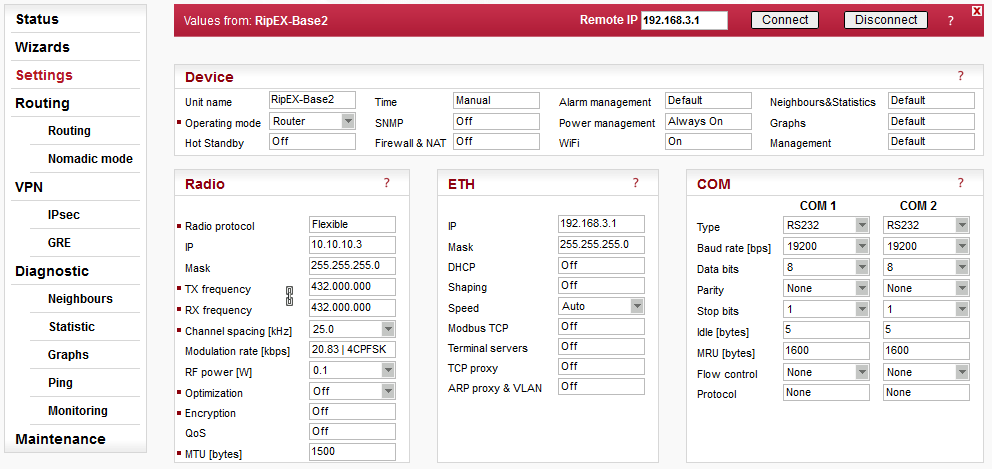
Only the different parameters compared to the central unit are explained below.
Parameters:
Unit name | RipEX-Base2 |
Radio IP/Mask | 10.10.10.3/255.255.255.0 |
ETH IP/Mask | 192.168.3.1/255.255.255.0 |
Parameters:
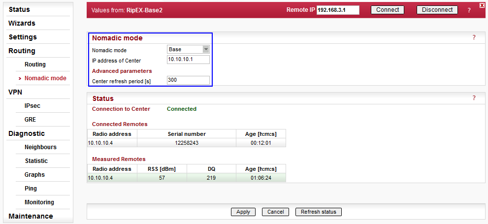
Nomadic mode | Base |
IP address of Center | 10.10.10.1 (RipEX-Center Radio IP address – the communication is operated via Radio channel) |
Advanced parameters:
Center refresh period [s] | 300 |
The Status menu is described in Chapter 2.5.1 once the complete network is configured.
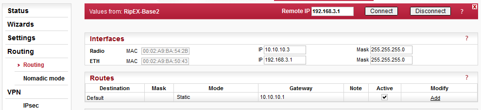
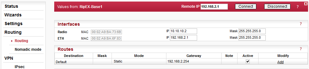
The only required route in this example is a default route, because the unit communicates only with the central unit (e.g. even with the Remote connected directly to this Base, the packets are transmitted via the central unit).
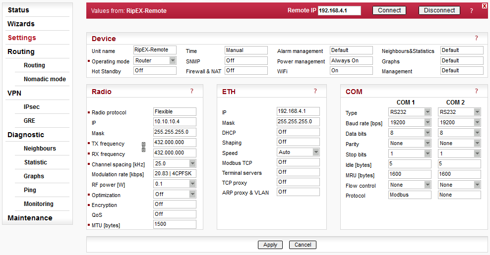
Only the different parameters compared to the central unit are explained below.
Parameters:
Unit name | RipEX-Remote |
Radio IP/Mask | 10.10.10.4/255.255.255.0 |
ETH IP/Mask | 192.168.4.1/255.255.255.0 |
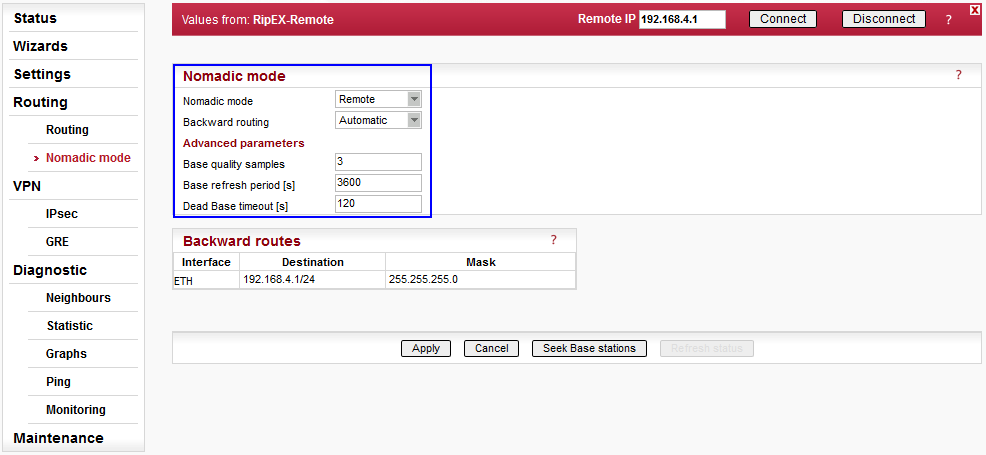
Parameters:
Nomadic mode | remote |
Backward routing | Automatic |
Advanced parameters:
Base quality samples | 3 |
Base refresh period [s] | 3600 |
Dead base timeout [s] | 120 |
The backward routing could also be set to Manual option, but in our example, it is much easier to choose the Automatic option, because it automatically uses the Ethernet subnet configured in this unit. This subnet is the only one required in our example.
The Status menu is described in Chapter 2.5.1 once the complete network is configured.
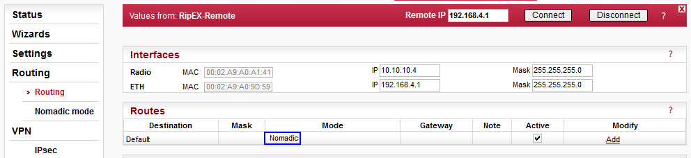
The routing table is different compared to other units within this example. All routes must be configured in the “Nomadic” mode. The only required route is the “Nomadic” default route which results in dynamic routing based on current conditions (location, RSS/DQ values, etc.).
Each Remote can be configured in the same way, they just require to have different Radio IP addresses and Ethernet subnets. The Routing menu is the same.
Status tables and information for different roles in Nomadic mode are described in this chapter. Examples of possible Remote unit locations are provided as well.
Central Unit
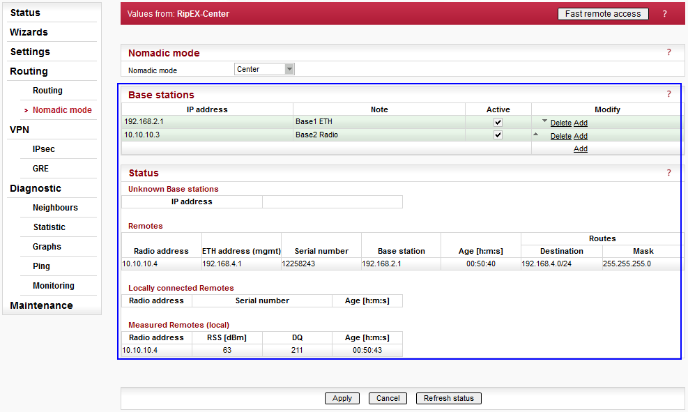
The menu displays the status of configured Base stations. The example utilizes two Base stations and both are accessible – i.e. both are highlighted in green. If any Base station is not accessible, it is highlighted in red.
Below the configured Base stations table, Unknown Base stations are displayed. These are Base stations that tried to connect with this Central station, but are not configured yet. A button “Add” can be pressed to add the unknown Base station to the list of configured/active Base stations. Entries older than 1 day, are automatically discarded.
Another table displays all the Remote units within the network. Each one of them is listed with:
Radio address
ETH address (mgmt) – use this address for the Fast Remote Access feature. The Radio address might not work in all cases.
Serial number
Base station – the IP address of the Base station to which the Remote unit is connected currently.
Age – the time of its last enrollment
Routes – the list of its backward routes
Each Remote unit (row) can be colored red if it is considered to be a “duplicated” remote. The pop-up notification “Suspected duplicated Remote” disappears once this unit is refreshed 8 times in a row without the serial number change.
The list of backward routes is colored:
“ok” (gray) – the rule does not collide and it’s successfully used.
“ok_coll” (light green) – the rule collides with another rule, but it is used.
“ok_backup” (light green) – the rule collides with a Backup routing rule. It is correct only if a backup path is “built” over nomadic route, otherwise it is a configuration error.
“coll_rmt” (red) – The rule collides with a routing rule from another remote. This rule is rejected.
“collision” (red) – The rule collides with local static routing rules or local interface subnets. It is rejected.
“loop” (red) – The rule would create a routing loop. It collides either with a base station or with the address range or radio interface. It is rejected.
Another table “Locally connected Remotes” displays the list of Remotes which are connected directly to this central unit. Each line consists of remote Radio address, Serial number and Age (time since the last refresh).
The last table “Measured Remotes” displays RSS/DQ values of Remote units which tried to communicate with this central unit directly. Entries older than 1 day are deleted.
Base Unit
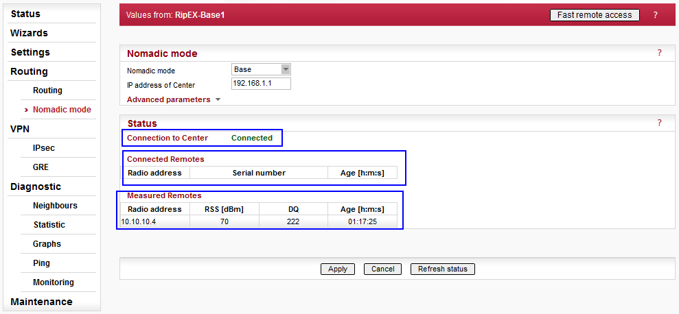
Within the Base Nomadic mode menu there are three parts. The first one displays whether this Base unit is connected to the central unit or not.
The “Connected Remotes” and “Measured Remotes” tables display the same information as explained in the central unit, because any central unit can also serve as a Base unit.
Remote Unit
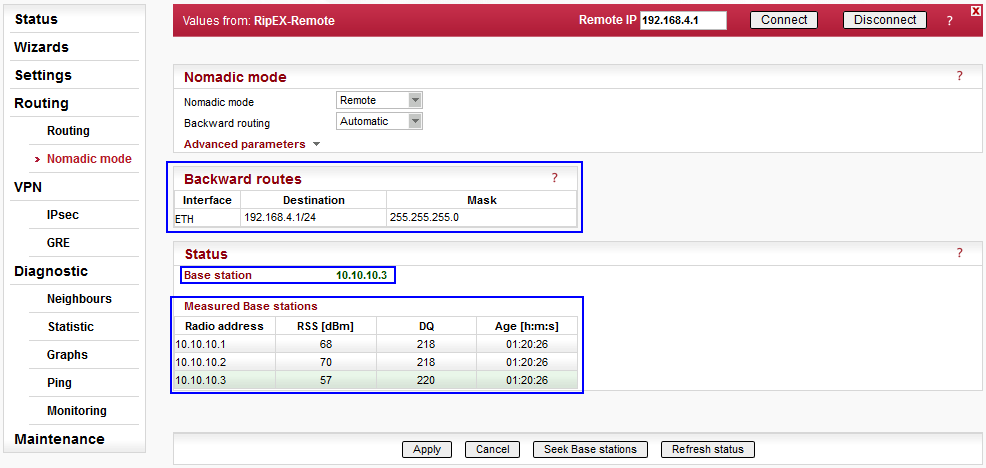
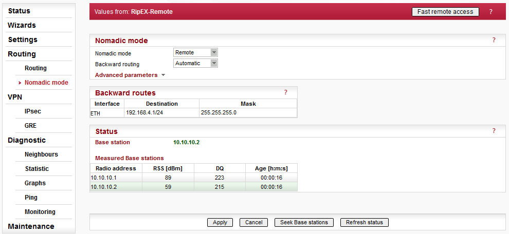
The first table “Backward routes” can be filled in manually or automatically. In this example, automatic option was configured and thus 192.168.4.1/24 backward route was set automatically (because this IP/mask is the local unit’s Ethernet configuration).
In the Status, the Radio IP of the currently used Base station is displayed.
Each Remote unit displays the list of all measured Base stations with their Radio address, RSS/DQ values and Age (time of the last measurement). If any Base station is not displayed, click on the “Seek Base stations” button to restart the process of selecting the best Base unit, or just refresh the page to reload the displayed information.
The selected Base is colored green. Others are gray. If the Base unit rejected this Remote’s connection, this Base unit is colored red.
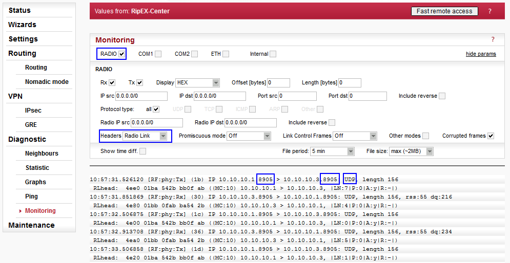
The nomadic traffic uses the UDP port 8905. The nomadic mode does not have its own monitoring interface, but it can be captured on the Radio interface after specifying the UDP port equal to mentioned number 8905.
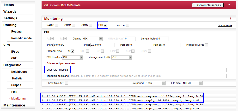
In the central and remote units, the ETH interface can be used to check the nomadic traffic as well. Put the advanced filter “-i nomad” as a User rule and start the traffic capture.
The Remote can be connected to the Central unit or one of the Base units. If the Remote is within the radio coverage of at least one of these Base units, it will work correctly. Based on measured RSS/DQ values, Remote unit dynamically chooses the best Base.
For our tests, all three possible Base stations will be selected by the Remote unit. One of the easiest way is to turn off and on particular units. You can simulate the same via changing the RSS/DQ values if you are using attenuators and coaxial cables for radio coverage. Or you can remove Ethernet cable between the central unit and Base1 unit. Decreasing configuration parameters’ timeouts should also speed up re-selecting the Base unit.
For any following scenarios, actual path of data can be verified in the Monitoring menu as well. Check the UDP port 8905 on the Radio interface or use the parameter ‘-i nomad’ for the Ethernet interface.
Turn off all RipEX units except the central unit and then, turn on the Remote unit immediately. Check that the Remote selected the central unit and turn on both Base units.
In this scenario, the Remote will be communicating with the central unit directly, via one radio hop.
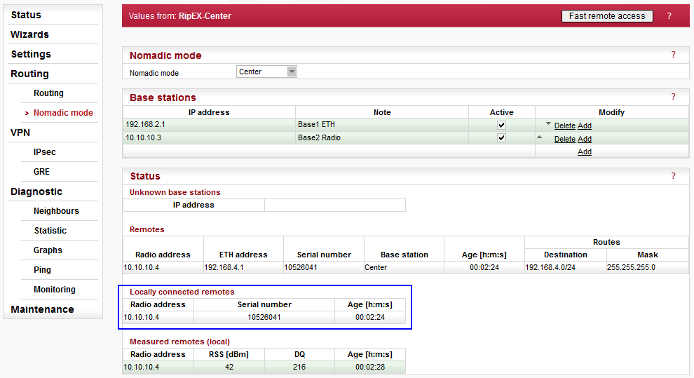
In the central unit, the Remote 10.10.10.4 is displayed as locally connected Remote.
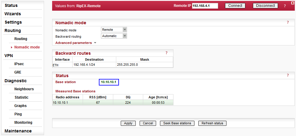
The menu displays the central radio’s IP for the selected Base unit. In the “Measured Base stations” table, there is only one entry. Currently, the Remote unit does not know about other Base units.
If the current Base station is not accessible for more than 120 seconds (there are no replies for data sent from Remote to this Base station), the “Base refresh period” is started to verify the Base accessibility. If the current Base is not accessible, a new “Seek” is started and a new Base is selected.
Click on the “Seek Base stations” button to start the process of selecting the best Base unit. The results might vary on your current signal values. Refresh the status and check the menu.
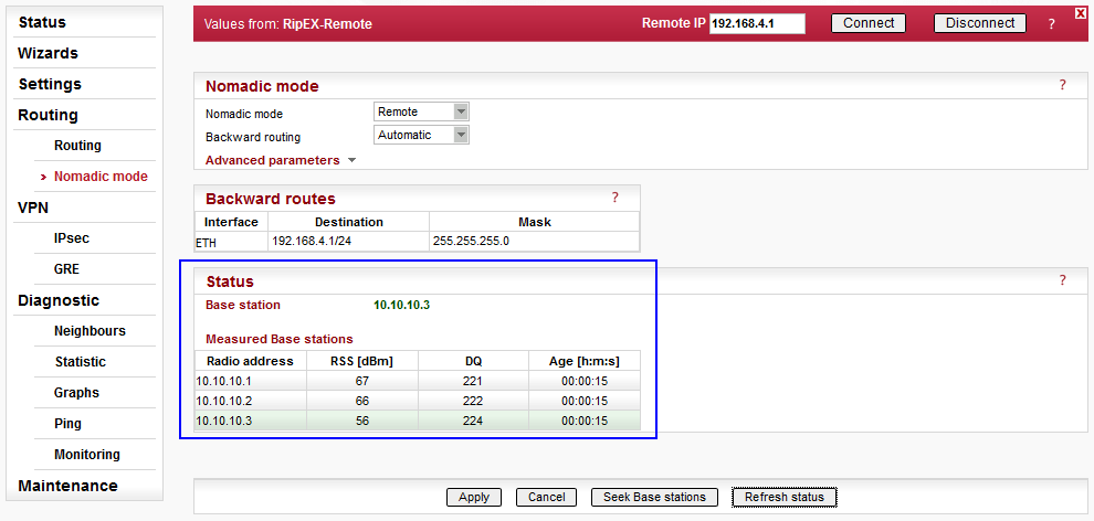
The current Base station is the Base2 unit (10.10.10.3).
NOTE:
The algorithm changes the current Base unit
only if the signal is more than 5 dBm better, otherwise it prefers the
current one.
A similar approach can be taken for Base1 unit. Turn off the RipEX-Center and RipEX-Base2 units. Press the “Seek Base stations” button in the Remote unit and check the status. The “Disconnected” status should be displayed.
In this scenario, the Remote will be communicating with the central unit directly, via one radio hop.
The reason is simple – at this time, there is no central unit, only one Base unit. Turn on the central unit and refresh the Remote’s status.
Verify the central unit accessibility via the Ping diagnostic tool.

NOTE:
Follow the same principles and simulate the
RipEX-Base2 selected as the best Base.