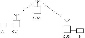
A packet entering the MORSE network must be provided with a destination address. This address is assigned to it in the user device A or B. This external device can determine the address for example as only a serial number from 1 to 5 if it works in a network containing 5 stations. Transfer of addresses to the MORSE form is then taken care of in the input part of the CU, most often the SCC serial communication channel.
This destination address (shortened to dest or dst) is carried in
the header of the packet along the whole route through the network. It
serves as initial information for each CU during routing, i.e. upon
determining the next step of the packets route. The packet also carries a
source address with it (src), according to which the destination CU
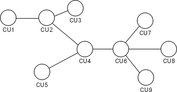
recognises whom it should send a reply. For example, see next drawing, a
packet sent in the subnetwork 69AABB00 from CU1 to CU6 thus has the
src address 69AABB01 and dst
address 69AABB06. The route
of the packet is divided into a number of steps between neighbouring CU,
here 1 > 2, 2 > 4, 4 > 6. For each of these steps routing is
resolved separately and the packet takes these two addresses of the
current step with it – from is the
transmitting CU and to is the receiving
CU. Addresses contained in the header of the MORSE packet are thus:
src, from, to, dst
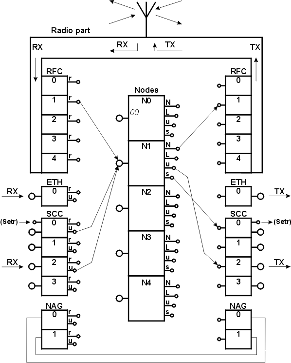
All routing operation run in any of the 5 nodes contained in the CU. In the node the address to is assigned to the passing packet in the manner described below and the packet is sent via any of the four node outputs on its next route through the MORSE network. The function of the node is described in the chapter Routing 1.
For illustration here we give a record of the route of the signal
through three nodes from address 690F120F to address 690F1209 and back:
u S00   690F120F    R01
30/ 46  690F1200    R01
31/ 88  690F1209   serd

 serd   690F1209    R02
30/ 41  690F1200    R01
30/ 65  690F120F  u S00
690F1209h>
In the middle the route is marked by the sequence of addresses, on the right the channel is marked through which the packet left the node and on the left there is the strength of the received signal.
From the point of view of the internal construction an address is composed of 4 bytes called global, net, wide and local, see introductory chapter MORSE addresses. According to these parts of the address the node searches for the further information in the routing (or store and forward) tables. The order of these node activities is discussed in the following chapter Routing 1. Here you can see work with the routing tables.
From the MORSE main menu selecting:
>> T Enter
we get:
Retranslation table:
  (l)ocal
  (w)ide area
  (n)et
  (g)lobal
(q)uit
>>
We select which type of table we would like to work with, for example for table wide:
>> w  Enter

Wide retranslation table No:
  (1) (2) (3) (4)
(q)uit
>>
The table can be prepared in up to 4 versions so that each node can have a different table available. Select table number one:
>> 1 Enter

Retranslation table:
  (r)ead nontrivial paths
  (p)ath:0 via (n)ode:0
  (g)et p(u)t
  (c)lear  (e)dit
(q)uit
>>
Using the function (r)ead we can read the contents of
the table:
>> r Enter

Wide retab. No 1
14to:1105 15to:150A
>>
Using the function (c)lear we can delete the whole
table. An entry is made using (p)ath and (n)ode
with a subsequent (p)ut. If an entry is made using the
standard procedure as follows:
>> p 14 Enter
>> n 1105 Enter
then it is not necessary to use the command
p(u)t.
Upon writing to individual tables this length of address is used for
the item (n)ode:
 global
   69112233
 net
   69112233
 wide
   2233
 local
   33
The item (p)ath always has the length of one byte, e.g.
22.
Rules for creating the content of routing tables are described in the following chapter Routing 1.


