IPsec can be used in a network of any size. A dedicated router (or several routers) serve(s) as the VPN concentrator. The choice of vendor and type depends on the SLA requirements and the size of the network – RACOM has positive experience with Cisco routers (IOS or ASA based), however routers from other vendors (e.g. Juniper, Netgear, WatchGuard or others) can certainly be used.
The following routers were used as IPsec VPN concentrators:
M!DGE/MG102i – up to 4 tunnels
Cisco 1700 – up to 100
Cisco ASA 5510 – up to 250
Cisco 871-K9 – up to 10 tunnels
Cisco 1841-HSEC/ K9 – up to 800 tunnels
Please follow the instruction in the user manual of the specific router for IPsec tunnel settings. RACOM support team can assist you with basic settings for Cisco routers. A short description of the IPsec tunnel configuration in M!DGE/MG102i follows.
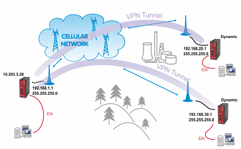
The topology is the same as with the routed OpenVPN example. Remember that it is not possible to have a bridged mode of IPsec as it was possible with OpenVPN.
Both remote M!DGE/MG102i units in the example have dynamic mobile IP addresses. We will set the center’s peer IP to 0.0.0.0 so it will accept the connections from any IP address.
With IPsec, the most common way to authenticate each other is via a pre-shared key. Due to this, it is not essential to have a correct time using the NTP server.
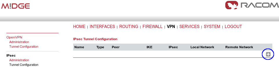
Go to the VPN – IPsec – Tunnel Configuration menu and create a new tunnel by pressing the “+” sign.
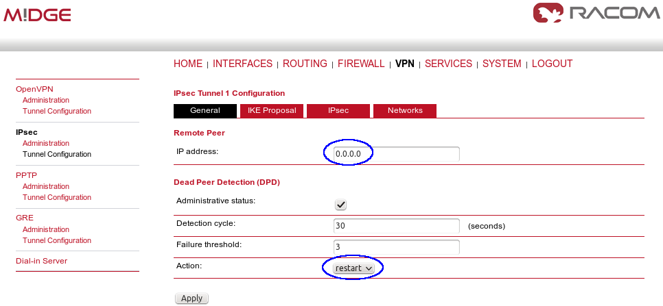
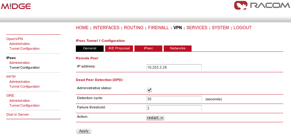
In the General tab, fill in 0.0.0.0 into the IP address field. Due to this address, any remote unit can establish the connection with the central unit if the credentials are correct. The remote unit’s IP address is not an issue.
| Note | |
|---|---|
From our experience, change the Action to “restart”. |
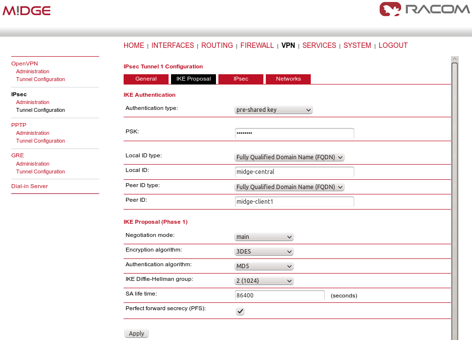
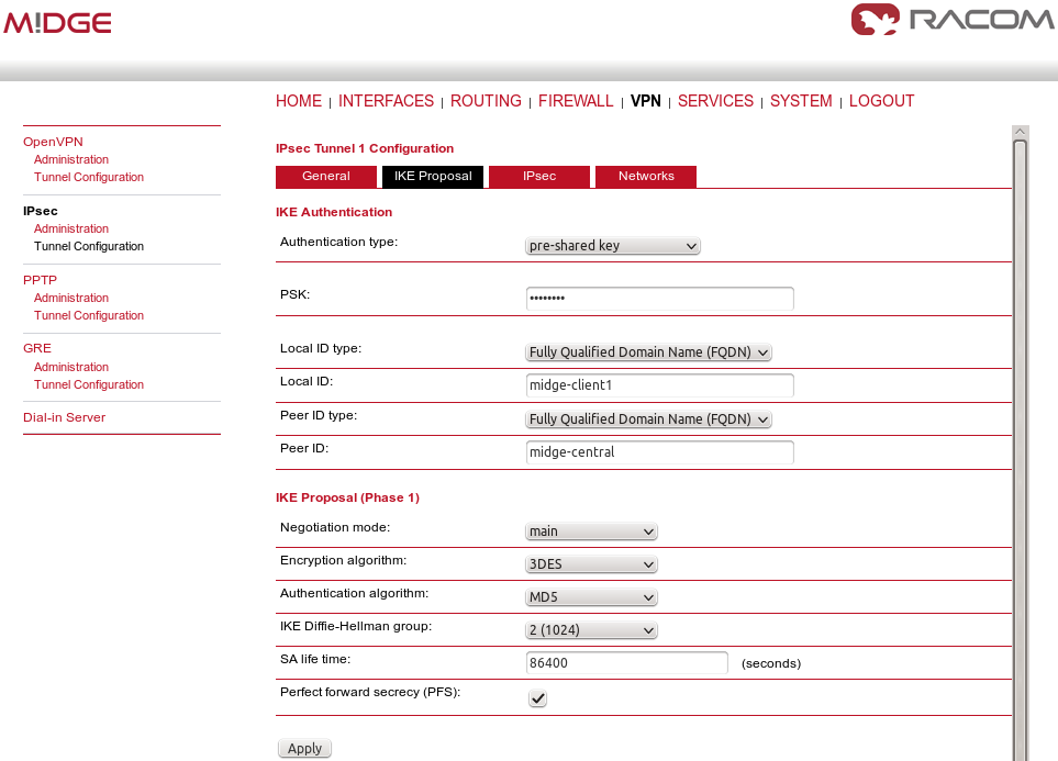
Apply the changes and go to the next tab, IKE Proposal. Define any pre-shared key, which must be the same on the center and the remote sites. Fill in the Local and Peer IDs. In our example, FQDNs are used. The central ID is “midge-central” and the ID for the first client is “midge-client1”.
| Note | |
|---|---|
You need to add a second tunnel if you need to connect M!DGE “client2”. |
Other parameters can stay in defaults or you can enable PFS for higher security.
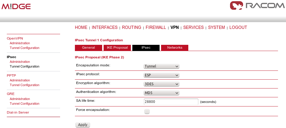
After applying the changes, you can leave everything in defaults within the IPsec Proposal tab.
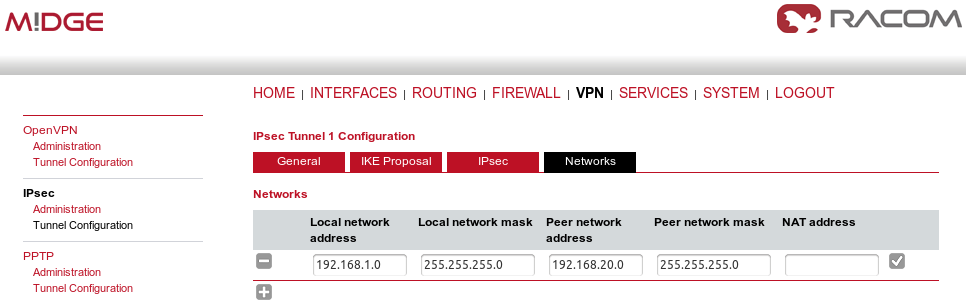
In the last tab, define the required routable networks. In our example, we interconnect server’s 192.168.1.0/24 subnet with client’s 192.168.20.0/24 subnet. Leave the “NAT address” blank.
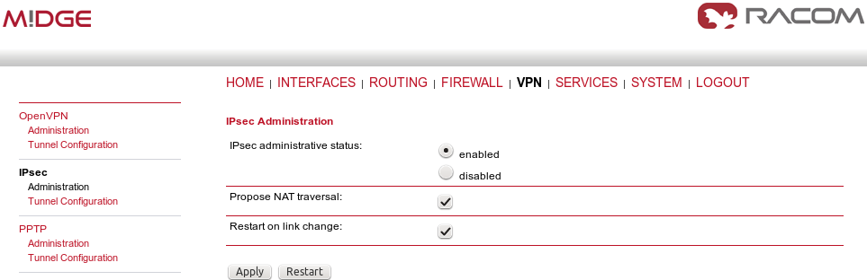
Return back to the Administration menu and enable the tunnel. Check both parameters – Propose NAT traversal and Restart on link change.
The pop-up window will appear asking you to confirm the MSS to be decreased due to IPsec overhead. Confirm this change.

If you now check the tunnel status, it will be “down”, because the client’s configuration is not yet finished.
The client’s configuration must follow the server’s one. The Peer IP address must be the server’s IP address.
In the IKE Proposal tab, the PSK must be the same as on the server’s side and switch the IDs. Do not forget to enable PFS if checked on the server.
Leave IPsec proposal in defaults and configure the Networks. Just switch the subnets (compared to the central’s configuration).

We can now Enable the tunnel and confirm the MSS adjustment.
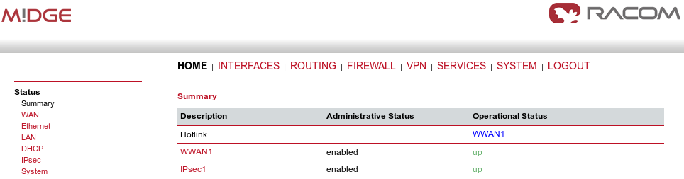
After the algorithmcompletes the tunnel establishment, the tunnel should be marked “up” on both units. Check the HOME menu.
Once the tunnel is UP, you can check the functionality via the ping, e.g. from the command shell:
~ $ ping -I 192.168.1.1 192.168.20.1
PING 192.168.20.1 (192.168.20.1) from 192.168.1.1: 56 data bytes
64 bytes from 192.168.20.1: seq=0 ttl=64 time=849.734 ms
64 bytes from 192.168.20.1: seq=1 ttl=64 time=1058.866 ms
64 bytes from 192.168.20.1: seq=2 ttl=64 time=918.134 ms
You need to set the source IP address so the IPsec routing would work. Otherwise, there could be no route back from the remote M!DGE.
Use M!DGE/MG102i manual for more details.