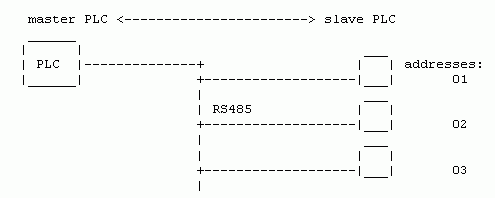
The standard format of the MODBUS protocol contains a single Master and a group of Slaves connected over the RS485 network. The Master cyclically calls individual Slaves and reads data from them. According to requirements the Master sends commands for Slaves. Each command from the Master is duly acknowledged or contains a response with data corresponding to the function of the frame. The Master does not have its own address. Slaves can have addresses in the interval from 1 – 247, address 0 is used for modbus broadcast function.
The next figure shows the Modbus network connected by the MORSE radio network.
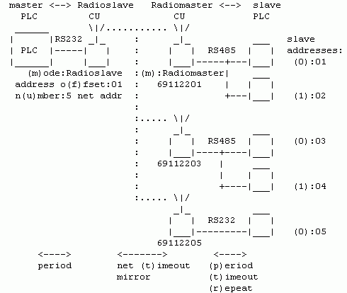
The Slave PLCs are connected individually or in groups to the MORSE CU (communication unit, modem, radio), which locally take on the function of the Master PLC.
The Modbus bus is interrupted by an inserted radio network which mediates the connection in the following three modes. Radioslave (RS) and Radiomaster (RM) are CUs with the Modbus protocol.
Radioslave has a Modbus address the same as the lower byte of its
own MORSE address. The lower byte of the CU Radiomaster address is the
same as one of the addresses of connected Slave PLCs. For directing other
PLCs the “multiaddressing” function in menu (N)odes
(e)dit is used. Characters in brackets such as (p)eriod
identify protocol parameters. An example of addresses is also
given.
MODBUS protocol for MORSE can operate in three modes
transparent
cache
packet
Transparent Mode
All packets that come from the connected Master PLC to the CU Radioslave are immediately transmitted through the MORSE network to the respective remote CU Radiomaster and transferred to the Slave PLC. A packet must contain the Slave address in the first byte and the Modbus function number in the second byte and then data and finally the checksum. The packet passes through the protocol and MORSE network without change. A message from the Slave PLC is only accepted as a response to a query and is sent to the questioner´s address. The mode is only suitable for small networks with a longer Master – Slave query interval.
Cache Mode
CU Radiomaster queries the connected Slave PLCs in the short
interval (p)eriod and stores obtained data in its cache
memory. Only when there is a change in the data in this memory is a packet
sent through the MORSE network to the CU Radioslave. This maintains data
from all Slave PLCs connected via the MORSE network. Upon a query, within
a short period, it then passes data to the Master PLC. The transfer of
commands from the Master to the Slave, which is less frequent, occurs in
transparent mode.
Cache mode transmits only data changes (+ refresh over a longer time interval) through the MORSE network, which is why it is suitable for larger networks. A Slave can only transmit as a response to a received command. Direct Slave – Slave communication is not possible.
In Cache mode the Master serves a max. of 50 Slaves in fw 740, from fw749 max. 250 Slaves for MR400 or 50 Slaves for MR25.
Packet Mode
In packet mode periodic
master <—> slave communication is maintained
over wire links RS485 or RS232, i.e. Master
PLC <—> Radioslave,
Radiomaster <—> Slave PLC. In this case only
a short descriptor is transmitted and only then in the case of new
information is the whole data buffer transmitted. Based on information
from the data buffer the CU generates a MORSE packet which is sent through
the MORSE network to the destination CU.
This is where the differences between master – slave disappear. A Slave PLC can send a message without a call and also for another Slave PLC.
Transparent and Cache modes or also Transparent and Packet modes can operate simultaneously. Transparent mode is usually used in these cases for service work on a PLCs. All modes require that the Master is able to wait a longer time (seconds) for a response to a command from a Slave.
All modes
require that the Master is able to wait a longer time then at the communication on simple wire link for a response to a command from a Slave. The response on SCC comms after tens msec, the response on RFC can comm at wrong conditions after a number of seconds.
Overview of Modbus functions for reading and entering data from various parts of the PLC memory. A more detailed description is given in article “Formatting MODBUS frames for MORSE”.
  function/8    unit for:     PLC
     (hex)       start/16
                number/16

     read    <--           ___________
     write   -->          |           |
                          |   Bin     |
        02   <--   bits   |    IN     |<- physical input
                          |           |<-
                          |___________|<-
        01   <--   bits   |           |
        05   -->  1bit    |   Bin     |-> physical output
        0F   -->   bits   |   OUT     |->
                          |___________|->
                          |  Analog   |
        04   <--   words  |    IN     |<-
                          |___________|
        06   -->  1word   |           |
        03   <--   words  | Holding   |
        10   -->   words  | Registers |
        17   <-->  words  |           |
                          |___________|
An overview of the formats of Modbus functions (No. of function, direction of transfer of information, name of function, size of unit num is 1 or 16 bits):
Master-Slave        REQUEST from Master   | RESPONSE from Slave
   <-->                                   |
01 <--  B_out            01               |
02 <--  B_inp            01       |
|adr/8| fce/8| start/16| num/16| crc/16|  |adr/8| fce/8| cnt/8| data/8*cnt|crc/16|

03 <--  H_Reg            16
04 <--  Inp_R            16
|adr/8| fce/8| start/16| num/16| crc/16|  |adr/8| fce/8| cnt/8| data/8*cnt|crc/16|

05 -->  B_out
|adr/8| fce/8| start/16| 0xFF00| crc/16| =set 1 bit ON
                                          |adr/8| fce/8| start/16| 0xFF00 |crc/16|
|adr/8| fce/8| start/16| 0x0000| crc/16| =set 1 bit OFF
                                          |adr/8| fce/8| start/16| 0x0000 |crc/16|

06 -->  H_Reg
|adr/8| fce/8| start/16| data/16| crc/16| =write 1 word
                                          |adr/8| fce/8| start/16| data/16|crc/16|

0F -->  B_out            01
|adr/8| fce/8| start/16| num/16| cnt/8| data/8*cnt| crc/16|
                                          |adr/8| fce/8| start/16| num/16 |crc/16|

10 -->  H_Reg            16
|adr/8| fce/8| start/16| num/16| cnt/8| data/16*num|crc/16|
                                          |adr/8| fce/8| start/16| num/16 |crc/16|

reply to the command entered incorrectly   Err
|adr/8| 0x80+fce /8| excode/8| crc/16|| adr | address of PLC on Modbus busbar |
| fce | function which the PLC performs upon receiving a frame |
| start | start address of data (output) which will be processed |
| num | number of words (f03,04,10,17) or bits (f01,02,0F) for reading or writing |
| cnt | number of bytes necessary for the transfer of the requested data |
| data | states of read or written registers |
| crc | security word |
| excode | number of exceptions, specifies error
|
Example of communication:
15:28:06.780 tx      8 | S00
0403 1000 0001 809F
15:28:06.784 rx;i    7 | S00
0403 0200 0074 44
| 04 | questioned address |
| 03 | reading from Holding register |
| 1000 | from address 1000 |
| 0001 | read 1 word |
| 809F | crc |
| 04 | answering address |
| 03 | reading from Holding register |
| 02 | 2 byte read |
| 0000 | content of read bytes |
| 7444 | crc |
Modem mode is set up (for SCC2 here) in menu
SPe2t:
MODBUS parameters:
PLC Master - CU RADIOSLAVE ... CU RADIOMASTER - Slave PLC
(m)ode:RADIOSLAVE (wired to master)
(a)utomaster:OFF
(c)ache:ON  (p)acket:OFF  (t)rans:ON

(M)aster (S)lave
(A)utomaster
(C)ache
(P)acket
(T)rans

(s)ervices    De(f)aults menu
(O)ld menu (sw ver =< 5.74)
(q)uit
>>
| (m)ode | (m)ode:RADIOSLAVE (wired to master) – Modem position in the network |
| (a)uto | (a)utomaster:OFF – The Radioslave can have the automaster function switched on. It then assumes the Radiomaster function when communication over RS485 is interrupted. |
| (c)ach | (c)ache:ON – Mode selection. |
| (p)ack | (p)acket:OFF – Mode selection. |
| (t)rans | (t)rans:ON – Mode selection. |
| (M)ast | This and next menus contain the parameters for chosen modes. |
The radioslave is connected via the SCC to the PLC Master and from the Master’s point of view represents all PLC Slaves in the network. The addresses of all PLC Slaves are defined for RS using parameters o(f)fset and n(u)mber. Based on the mode defined in menu SPe2t RS then communicates with RM modems which are located by individual PLC Slaves.
slave parameters:
address o(f)fset:1  n(u)mber:5  net addresses
address type (o)ut: MORSE
address type (i)n: MORSE
(r)epeat discard:5 (deprecated)
d(e)vice type:PLC
Sep (a)ddress:5
(q)uit
>>
| o(f)f | address o(f)fset:1 – PLC Slave addresses form a continuous series. The lowest of them is given here, the min. value is 1 |
| n(u)m | n(u)mber:5 – Number of serviced PLC Slave (max. 50 for fw up to 740, fw 749 and higher with MR400 manages up to 250 Slaves, for MR25 the limit is 50 Slaves) |
| (o)ut | address type (o)ut: MORSE/MODBUS – for packets leaving to the network the address of the target PLC Slave is derived either from its MORSE address or from its MODBUS address contained in data. |
| (i)n | address type (i)n: MORSE – for packets incoming from the network the address of the source PLC Slave is derived either from its MORSE address or from its MODBUS address contained in data. |
| (r)ep | (r)epeat discard:5 (deprecated) – Any parameters which have been cancelled or are not recommended are marked ”deprecated”. |
| d(e)v | d(e)vice type:PLC – type of connected PLC Slave:
|
| (a)dd | Sep (a)ddress:5 – If PLC+MTD mode is switched on then the range of addresses for MODBUS PLC and MTF devices is defined here (addresses lower than Sep Address are always MODBUS PLC addresses; addresses equal and higher than Sep (a)ddress are reserved for MTF devices – ADIO, SEP) |
Radiomaster appears in the MORSE network under an address, the
last byte of which is the same as one of the Modbus slave
addr:, e.g. 69112203. Messages for the next of
them are received using the Multiaddressing function (in menu
Ne). The address of the respective Radioslave is given in
item (d)estination:.
Communication over the RS485 line (or RS232 for a single Slave)
occurs with a (p)eriod: (here 200 ms), wait for a max.
period of (t)imeout: for a response, (r)epeat:
number of repeats after (t)imeout.
master parameters:
(d)estination:691122FFh  destination
d(e)vice type (deprecated):PLC
Modbus slave addr: (0):3 (1):4 (2):5 (3):0
Modbus slave addr: o(f)fset:1  n(u)mber:0
address type (o)ut: MORSE
address type (i)n: MORSE
(a)ddress mask:FFh (deprecated)
(p)eriod:20 period i(n) : *10ms
(t)imeout:10*100 ms
(r)epeat:2
DPM(B) bcast compat:OFF
(q)uit
>>
| (d)est | (d)estination:691122FFh – Radioslave address in the MORSE network, uses Cache mode for sending messages RM -> RS, also for error messages. |
| (0) | Modbus slave addr: (0):5 (1):0 (2):0 (3):0 – List of Slave
stations included in the polling cycle; addresses need to be
filled from the parameter (0), e.g.:(0),(1),(2); from sw 749 Modbus slave addresses are entered
in decimal format. If the
number of Slaves is higher, then the
parameters |
| o(f)f | Modbus slave addr: o(f)fset:1 – Defining the starting
address for the longer interval of PLC addresses; multiaddressing
in |
| n(u)m | n(u)mber:0 – Number of PLC´s, interval begins from (o)ffset, from sw 749 |
| (o)ut | address type (o)ut: MORSE/MODBUS – The source PLC Slave address for packets outgoing to network is derived from it’s MORSE address or from MODBUS address contained in the data. The MORSE option is chosen for one PLC with an address that is the same as the last byte of the node. The MODBUS option is chosen in the case of more PLCs on a bus or if the address of the PLC is different to that of the node. |
| (i)n | address type (i)n: MORSE/MODBUS – The destination PLC Slave address for packets incoming from network is derived from it’s MORSE address or from MODBUS address contained in the data. |
| (p)er | (p)eriod:20 – Period for polling Slave stations on RS485 or RS232, the time between receipt of a response and transmission of a new query, for the Cache and Packet mode. The size of time unit is defined in the next parameter. |
| i(n) | period i(n) : *10ms / sec – the time unit for the (p)eriod is 10ms or 1sec. Here is the period set to 20*10ms = 200ms. |
| (t)im | (t)imeout:10*100 ms – Max. time for waiting for a response on SCC. For the waiting period the SCC is not active and therefore does not even transfer any other incoming packets. |
| (r)ep | (r)epeat:2 – Max. number of repeats on SCC |
| (B) | DPM(B) bcast compat:OFF – Special parameter for DPMB. |
In transparent mode all data is transmitted from Master to Slave over the network. It is used for transmission of executive commands from the Master in Cache mode. For bidirectional transmission transparent mode is only suitable for very small networks with a slow “timeout” polling cycle. For restricting the transmission of spurious packets we use checks in RM, as below.
After sending a packet to a Slave the Radiomaster expects, in a max. period of SPe2tMt (= timeout), a response from the Slave, which is then sent through the MORSE network to the Radioslave.
RM replies to the MORSE address of the source. This allows there to be more transparent RS in the network.
transparent parameters:
(A)rt table No:0
# ART dest:       gw:
#     mmnnffff    hhhhllll
#    mtf No Fce     high low addr (use help in default menu)
# BEWARE! IF YOU CHANGE CONTENT OF THE TABLE,
# YOU SHOULD RESTART (INIT) THIS PROTOCOL!
check (f)unction:ON
check a(d)dress:OFF
check (C)RC:OFF (deprecated)
check (n)et No:OFF
allow (r)ead req:OFF
(D)etect transp/cache<->packet by :CRC
Net(B)ase:0000  Net(M)ask:0000
(c)ommand cache:OFF  (t)im::0s
(q)uit
>>
| (A)rt | (A)rt table No:0 – Table Art is generally not
used. |
| (f)un | check (f)unction: – This and other controls serve for barring unauthorised packets which may appear during transparent transfer.
|
| a(d)d | check a(d)dress: – Checking the Slave PLC address.
|
| (n)et | check (n)et No: – Checking the packet numbers.
|
| (r)ead | allow (r)ead req: – Inserting the transparent commands in Cache mode.
|
| (D)et | (D)etect transp/cache<->packet by : – If packet mode as well as other modes are switched on simultaneously it is necessary to distinguish how an incoming packet should be processed. This setting is common for all three modes and can be set up from menu SPe2tT (T)rans or (C)ache or (P)acket. Options:
|
| (B)ase | Net(B)ase:00FF – “Base” setting for distinguishing between Transparent/Cache and Packet mode. It works with down half of MORSE address only. |
| (M)ask | Net(M)ask:FFFF – “Mask” setting for distinguishing between Transparent/Cache and Packet mode. |
| (c)om | (c)ommand cache: – The PLC Master sends Modbus queries to RS. Some PLCs expect a response in a shorter time than the transfer time over the radio channel from RS to RM and back. In such a case the PLC repeats the query thus excessively flooding the RF channel. For this reason we use the (c)ommand cache, which sends the first query and discards the rest until the time according to (t)im has expired or until a response to the query arrives back. This is set up in RS mode.
|
| (t)im | (t)im:10s – Timeout for |
CACHE mode is used for collection of data from a larger number of
PLC Slaves. It is supplemented by Transparent mode for transmission of
(less frequent) commands in the Master –> Slave
direction.
In cache mode identical memory areas – cache – are created in the
PLC and in modems. Transmission of data from Slave –> RM
occurs on the link with short period SPe2tMp set in the
range of 100 to 200ms. This maintains the current image of the status of
connected Slaves in RM. If there are no changes in this image it is sent
over the radio to RS in intervals SPe2tCt. If a change
occurs in RM cache, a message for RS is sent immediately. Thus
current images of the cache of all connected Slaves are maintained in RS
cache with minimum loading of the radio network. PLC Master then reads
this cache in RS in the same way as if it had read the status of all
Slaves over the Modbus network.
On monitoring the status of cache memory the whole content of
cache is transmitted over the link. Polling is controlled by the
Radiomaster or the PLC Master. Information is only transmitted in the
Slave –> Master direction.
    cache parameters:
(A)rt table No:1
# ART dest:       gw:
#     mmnnffff    hhhhllll
#    mtf No Fce     high low addr (use help in default menu)
# BEWARE! IF YOU CHANGE CONTENT OF THE TABLE,
# YOU SHOULD RESTART (INIT) THIS PROTOCOL!

(D)etect transp/cache packet by :CRC
Net(B)ase:0000  Net(M)ask:0000
net (t)imeout - mirror:30s
a(l)iasing:OFF
(g)lue to trans:off
(e)rr. report:SILENT  err. (a)dr:0h  err. (m)ask:0000h
(o)ld cache menu (since sw.630)
(q)uit
>>
| (A)rt | (A)rt table No:1 – number of ART table where cache memory is defined, more detailed explanation follows. Fill in the Art table first and after it the SPe menu. |
| (D)et | (D)etect transp/cache<->packet by : – If the Packet mode and any other are used together then it is necessary to distinguish how the incoming packet should be processed. This setting is common for all 3 modes and can be set in menu SPe2tT (T)rans or (C)ache or (P)acket. Possibilities:
|
| (B)ase | Net(B)ase:00FF – Base setting for distinguishing between Transparent/Cache and Packet mode. Only low half of MORSE address is used. |
| (M)ask | Net(M)ask:FFFF – Mask setting for distinguishing between Transparent/Cache and Packet mode. Only low half of MORSE address is used. |
| (t)im | net (t)imeout – mirror:30s – Period of reporting to RS, if no change in cache occurred. |
| a(l)i | a(l)iasing:OFF – Common cache for all functions:
|
| (g)lue | (g)lue to trans:off
|
| (e)rr | (e)rr. report:SILENT – Behaviour in the case of a loss of
communication on the line RM
|
err. (a)dr:0h  err. (m)ask:FFFFh

10:30:47.087 tx      8 | S03
0503 0010 0003 058A
10:30:47.148 rx;i   11 | S03
0503 06AA AABB BBCC CC12 33
10:30:49.149 tx      8 | S03      ...connection on RS485 broken
0503 0010 0003 058A
10:30:52.151|                 |691122FF 00000005|S03I  OUT  11||89 4usr 0
0503 06FF FFBB BBCC CC12 3A
Zero word of the data AAAA is changed to FFFF by operation OR.
| |
| (a)dr | err. (a)dr:0h – parameter for MASK mode – address of word from the beginning of the block cash memory |
| (m)ask | err. (m)ask:0000h – parameter for MASK mode – a word, which is added (OR) to a selected word of memory cache |
Art and CACHE tables
Memory blocks for the cache function are defined in the same way in RS and RM using Table Art. For standard Modbus communication Art defines one cache memory in each of its rows. It contains a sequence number, Modbus function and the range of reserved memory. Example:
ART No 1:
items: 3
default gw: 00000000 (0.0.0.0   )
dest:    gw:
00040002 00040000 (0.1.0.2    0.4.0.0   )
00050003 00020000 (0.2.0.3    0.2.0.0   ) ...length 2 word
00060003 00140010 (0.3.0.3    0.20.0.16 ) ...length 4 word
>>
Writing format for dest and gw:
| rez/8 | No/8 | rez/8 | fce mb/8 | high addr/16 | low addr/16 |
rez/8 – reserve, 00
No/8 – sequence number, arbitrary, serves for distinguishing between dest items in the case of the same modbus functions
fce mb/8 – number of Modbus function (01, 02, 03, 04). A function recorded with an upper bit 1, i.e. 81, 82, 83, 84, creates a memory block which is not transferred immediately after a change of contents. It is only transferred to RS upon a change of another block or after time
SPe2tCt. Valid from version 10.0.20.0.high addr/16 – address of high end of memory space
low addr/16 – address of high end of memory space
For example the third row defines the cache memory for function 03 – reading registers, which contains 4 words at addresses 0010, 0011, 0012, 0013.
Responses to Modbus queries are stored in individual cache memories based on the number of the Modbus function. If there are more records with the same function number they are distinguished by their length. Memory for functions with the same number must be defined such that they can be differentiated by their length and must be listed in Art from the shortest at the top to the longest at the bottom. A PLC Slave must provide data for all cache defined in this way. If data is shorter then communication doesn’t take place.
It is possible to define a max. of 8 cache memories in Art. The maximum volume of all defined cache is 1400 byte in the case of the Radiomaster. This means that upon refreshing cache in the Radiomaster -> Radioslave direction a MORSE packet of maximum size 1400 bytes of user data can pass through the network.
For the Radioslave (in the centre) the memory in the modem is a
limiting factor.
Allocated memory in the centre =
(NumberPLC+NumberSEP+NumberADIO) × SizeCache
For MR25 allocated memory is < 5000 Byte
For MR400 allocated memory is < 250 000 Byte
ADIO, SEP and MTF in the Modbus
The Master PLC can communicate with Slaves ADIO or SEP, which work with the MTF format.
These devices are defined in RS in the (S)lave menu using parameters SPe2tSe, SPe2tSa. Table Art then performs a transfer between functions MTF and Modbus. Besides CACHE memory blocks for reading from modules ADIO and SEP a RULY blocks are defined for writing. Here is the recommended configuration of Art with comments:
dest:    gw:                            ...CACHE, MB <-- SEP
06010001 00080000 (6.1.0.1   0.8.0.0  ) ...read Dout   8 bit
01020002 00100008 (1.2.0.2   0.16.0.8 ) ...read Din    8 bit
07030004 000C000A (7.3.0.4   0.12.0.10) ...read Aout   2 word
02040004 00090001 (2.4.0.4   0.9.0.1  ) ...read Ain    8 word
                                        ...RULY, MB --> SEP
07070006 01020100 (7.6.0.6   1.2.1.0  ) ...write Aout  2 word
06080005 00080000 (6.8.0.5   0.8.0.0  ) ...write Dout  8 bit
0609000F 00080000 (6.9.0.15  0.8.0.0  ) ...write Dout  8 bit
Contain of dest and gw items:
| mtf/8 | No/8 | rez/8 | fce mb/8 | high addr/16 | low addr/16 |
mtf/8 – MTF function number, format see Protocol MTF for MORSE
No/8 – sequence number, arbitrary, serves for distinguishing between dest items in the case of the same modbus functions
fce mb/8 – Modbus function number for CACHE (1, 2, 3, 4, version 81, 82, 83, 84 see above) or for RULY (5, 6, F)
high addr/16 – upper end of memory space
low addr/16 – down end of memory space,
the address in bits or in words depending on Modbus function type, see chapter Data format
A maximum of 8 CACHE can be defined.
Memory with the same Modbus function number (here rows No 3 and 4) are again distinguished by length and listed from shortest to longest.
The table in question is suitable for communication with module ADIO and SEP. The Master PLC must send queries corresponding to the length of the connected device, e.g. for Din ADIO a query of 2 bits.
Tab. 1: Address used in SEP
| Oblast | Fce | Typ | SEP-Cache | Content |
|---|---|---|---|---|
| Dout | 0x01 | R | 00-07 bit | Read binary outputs |
| Dout | 0x05 | W | 00-07 bit | Write to bin. outputs in bits |
| Dout | 0x0F | W | 00-07 bit | Write to binary outputs |
| Dinp | 0x02 | R | 08-15 bit | Read from binary inputs |
| Ainp | 0x04 | R | 0x001-0x008 word | Read from analog inputs |
| Aout | 0x04 | R | 0x00A-0x00B word | Read from analog outputs |
| Aout | 0x06 | W | 0x100-0x101 word | Write to analog outputs |
Radiomaster sends a regular message for RS in the interval Net
timeout SPe2tCt. In addition to this it sends current
reports about changes. Radioslave monitors whether each RM reponds at
least once in time SPe2tCt.
If not it behaves
according to the error report setting.
Cache in RS is organised according to Modbus addresses or
according to MORSE addresses. If addresses do not begin with one the
unused part of memory for the Slave (0 to N-1) can be left out by using
offset addresses, parameter SPe2tSf. The number of blocks
of cache can then be adapted to the total number of Slaves in the
network using parameter SPe2tSu.
RS recognises individual Slave PLCs for their insertion into cache
according to MORSE addresses from which a message was received. If it is
necessary to distinguish PLCs according to Modbus addresses it is
possible to set up with the type of address in parameter SPe2tSo,
SPe2tSi.
In packet mode two memory buffers are created in each PLC and in
modems for transmission of data from Slave –>
Radiomaster (host to net, H2N) and back (net to host, N2H). The length
of the buffers is min. 250 bytes (max. length of Modbus frame), max.
1600 byte (max. length of MORSE packet).
Data transfer in packet mode can take place in any direction, i.e. Master<->RS, RM<->Slave, Slave<->Slave.
Radiomaster periodically queries each Slave for the content of the first word of the buffer H2N called the descriptor. If it is non-zero the length of the pseudoframe prepared in H2N is found out and this is transmitted in the next communication to the Radiomaster. Then the descriptor is deleted which indicates to the Slave the possibility of transmission of the next frame. Communication from PLC Master – RS, which is controlled by the Master, takes place in a similar manner.
Transmission from the Radiomaster (RM) to the Slave takes place in such a way that RM reads the descriptor N2Hdesc in PLC Slave and if it is zero it writes its pseudoframe to N2H. After processing this the Slave writes a zero word to N2Hdesc on the signal that buffer N2H is again available.
packet parameters:
Modbus (a)ddress:5
(A)RT table No.:0 (deprecated)
(N)2H buffer:2000  (H)2N buffer:1000
Warning: Both addresses should be nonzero.
(s)imulator:OFF
(D)etect transp/cache<->packet by :CRC
Net(B)ase:0000  Net(M)ask:0000
(q)uit
>>
| (a)ddr | – Modbus (a)ddress:5 — Modbus address of modem on 485 bus. |
| (N)2H | – (N)2H buffer:2000 — address of buffer for transfer “Net to Host”, which is MORSE Net to Modbus. |
| (H)2N | – (H)2N buffer:1000 — address of buffer for transfer “Host to Net”, which is Modbus to MORSE Net – addresses in memory at which the respective buffer starts for storing data sent by Modbus in packet mode. These addresses must be selected in a similar fashion for all Modbus network subscribers. Here the term Net represents the linking MORSE network starting with the node, and the Host is the connected PLC Slave or PLC Master. |
| (s)im | – (s)imulator:OFF — For testing purposes it is possible to
use the MORSE CU as a simulator for replacing the PLC Slave in
packet mode. Parameter |
Pseudoframes H2Nfr and N2Hfr have headers of length 6 bytes and data. The header contains the necessary information for creating a MORSE packet and sending it to the Radioslave or another Radiomaster.
Structure of buffers:
H2N:
| H2Ndesc/16 | H2Nfr/modbusMRU |
N2H:
| N2Hdesc/16 | N2Hfr/modbusMTU |
Description of items:
| H2Ndesc | “host to net descriptor”, and contains the necessary information for the transfer of a packet through Modbus. N2Hdesc (net to host descriptor) also has a similar format: H2Ndesc: |ret/1|rep/1|No/2|res/1|rxsize/11| N2Hdesc: |ret/1|rep/1|No/2|res/1|txsize/11|
| ||||||||||
| H2Nfr | user pseudoframe | ||||||||||
| N2Hfr | user pseudoframe | ||||||||||
| modbusMRU | Maximum Receive Unit | ||||||||||
| modbusMTU | Maximum Transmit Unit |
Addresses of individual blocks of memory (H2N, N2H) are freely configured in the modem according to the requirements of the connected device. A pseudoframe contains the actual packet determined for transfer to/from the network. A header containing network information is contained inside the pseudoframe. The header is located in the buffer in the next position after the descriptor. Structure of header and data:
User pseudoframe:
| T/8 | D/1 | R/4 | N/3 | A/32 | data |
| T | type of packet |
| D | bit DTE
|
| R | reserved, must be zero |
| N | network number (transmitted over the network) |
| A | address in network |
| data | actual data of pseudoframe |
Example:
The Packet mode frame transfering the data from RM to Slave:
                                     AA AA      ...data
                      09 0169 1122 FFAA AA      ...user pseudframe N2Hfr
                 00 0809 0169 1122 FFAA AA      ...N2H descriptor + N2Hfr
0510 2000 0005 0A00 0809 0169 1122 FFAA AAE5 E6 ...Modbus frame, record
                                                   with function 0x10
The frame transering data from Slave to RM:
                      BB BB       ...data
       09 8369 1122 FFBB BB       ...user pseudframe H2Nfr
0503 0809 8369 1122 FFBB BB0F B4  ...Modbus frame, reading
                                     with function 0x03
When reading data from the Slave to RM the descriptor is not read again because this is transferred in the previous step of the dialog. More detailed examples are given in a separate article.
Multiaddressing
Radiomaster, which serves several Slaves, uses Multiaddressing. When switching on the Multiaddressing function in the Nodes menu packets which were directed via routing to the node’s link output are sent to the user output. This therefore determines that packets from the MORSE network, determined for any of its Slaves, are accepted by the Radiomaster and that they leave its user port to SCC with Modbus.
Modbus automaster:
t(i)meout:0s
master mode after switching:
(c)ache:OFF  (p)acket:OFF  (t)rans:OFF
(q)uit
>>
| t(i)meout:0s | After this idle period on RS485 the Radioslave with switched
on parameter |
Time synchronisation in Modbus and watchdog for PLC Slave.
Modbus services:
(t)ime sync:OFF  (m)ode:RECEIVER  (p)eriod:0s
time (a)ddr:0000h  time sync (b)it:0000h
(d)ebug addr:00000000h (deprecated)
radiomaster only:
(w)dog bit:0000h  wd(o)g addr:0000h  wdog p(e)riod:0s  (F)unc16:OFF
(q)uit
>>
Parameters for time transfer:
| (t)ime | (t)ime sync: – Switch on function of transmission of timedata between the Radiomaster and Slave. |
| (m)ode | (m)ode:RECEIVER – Transmitting or receiving time mode:
|
| (p)er | (p)eriod:0s – Period for transferring time data is only defined in Radiomaster. |
| (a)ddr | time (a)ddr:0000h – Address for storing time, Master and Slave, set according to address used in PLC. |
| (b)it | time sync (b)it:0000h – custom function |
Parameters for watchdog are only entered in Radiomaster; they provide the PLC Slave with the option of checking whether a connection with Radiomaster lasts.
| (w)dog | (w)dog bit:0000h – Periodically written word to Slave. |
| wd(o)g | wd(o)g addr:0000h – Address of entry to Holding Registers in Slave. |
| p(e)r | wdog p(e)riod:0s – Period of entry. |
| (F)un | (F)unc16:OFF – funkce Modbus použitá k zápisu do Slave
|
Time Synchronisation
The Modbus protocol allows time to be transmitted between a MORSE CU and a connected Modbus device. In this way it is possible to link to time synchronisation in the MORSE network; see the example in the separate article. In all CUs it is necessary to switch on synchronisation SPe2tst and set up the address for recording time SPe2tsa the same way. There are four configuration options:
| RS receiver | time from PLC Master to RS, mode receiver, function 10, period 0 |
| RM sender | time from RM to PLC Slave, mode sender, function 10, period |
| RS sender | time from RS to PLC Master, mode sender, function 03, period 0 |
| RM receiver | time from PLC Slave to RM, mode receiver, function 03, period |
Parameter “period 0” means that Modbus communication is controlled by the other participant. Parameter “period” is set as required, e.g. 3600sec. If more PLC Slaves are connected to RM synchronisation only takes place with the first of them.
Example – RS in function SENDER accepts a time query from the Master PLC and responds:
12:01:47.831 rxsim   8 | S02
0503 3000 0006 CB4C
12:01:47.832 tx     17 | S02
0503 0C47 3984 1B03 402F 010C 0D0A 6BA4 84
Format of Time Data
|gmtsec/32|R/1|ts/1|R/4|msec/10|sec/8|min/8|hour/8|day/8|month/8|year/8|
| gmtsec | Current time. GMT in seconds since 1.1.1970 (Unix time) is used |
| R | Reserve |
| ts | Timesavings, switch between summer/winter time (1 – summer time, 0 – winter) |
| msec | Milliseconds in the current second |
Others are generated from the above mentioned items containing local time including a correction of the time zone. In the command for writing time to the CU the following items can be arbitrary, e.g. zero:
| sec | Current second |
| min | Current minute |
| hour | Hour (0 – 23) |
| mday | Day of month (1 – 31) |
| mon | Month (0 – 11) |
| year | Year (data in year format – 1900) |
Structure of used example:
0503 0C   - Modbus address 05, function 03, 12 byte
4739 841B - Unix time, seconds from 1.1.1970
0340      - 0000bit winter time, 0x340 = 832ms
2F        - 47 sec
01        - 01 min
0C        - 12 hod
0D        - 13 den
0A        - 10+1     = 11 month
6B        - 107+1900 = 2007 year
A4 84     - crc
12:01:47.832 – monitoring time corresponds with the
content of the frame
Watchdog Functions
PLC Slave does not have the possibility of finding out whether
communication with the Radiomaster has been interrupted or not. For that
reason it is possible here to set up the Watchdog function
in Radiomaster, which writes a particular word to a selected
address in the PLC Slave at regular intervals. Everything is set up
in menu SPe2ts. The PLC can then regularly read and
delete this entry thus maintaining information about the existence of
the connection.
Short description of types of packets on the user interface.
|U/1|B/1|H/1|subt/5|
| U | Link security bit – 1 denotes secure transmission | ||||||||||||||||
| B | Broadcast (multicast) bit – 1 indicates a broadcast packet | ||||||||||||||||
| H | Handicap/priority – 1 indicates lower priority (handicap) | ||||||||||||||||
| subt | Subtype – assumes these basic values:
|
Examples for transparent, packet and cache mode are given in a separate article MODBUS examples. Examples of packet mode are also contained in the older description MODBUS 574.
This description applies for version sw 10.0.9.0 z 9.10.2007.
Version sw 657 (4.3.2004) up to 678 also use parameters (deprecated).
Cache menu for versions up to sw 630 is contained in “SPe0tCo”.
Menu for versions up to sw 574 is in “SPe0tO”.
Description for sw 574 (20.5.2002) with more detailed explanation and with examples of packet mode is in article “MODBUS 574”.