GRE (Generic Routing Encapsulation) is a tunneling protocol developed by Cisco Systems that can encapsulate a wide variety of network layer protocols inside virtual point-to-point links over an Internet Protocol network. The GRE Tunnel can be configured between any two devices that are compatible with this protocol.
There are 2 modes of GRE operation: TUN (Tunnel mode) or TAP (L2 transparent connection) with SW bridge.
Packets passing through the GRE tunnel are not encrypted. You can combine GRE with IPsec for encryption purposes.
The GRE tunnel neither establishes nor maintains a connection with the peer. The GRE tunnel is created regardless of peer status (peer need not exist at all).
The GRE tunnel has its own IP address and mask. Network defined by this address and mask contains only 2 nodes – each end of the tunnel.
See Chapter GRE in the manual M!DGE for descriptions of parameters.
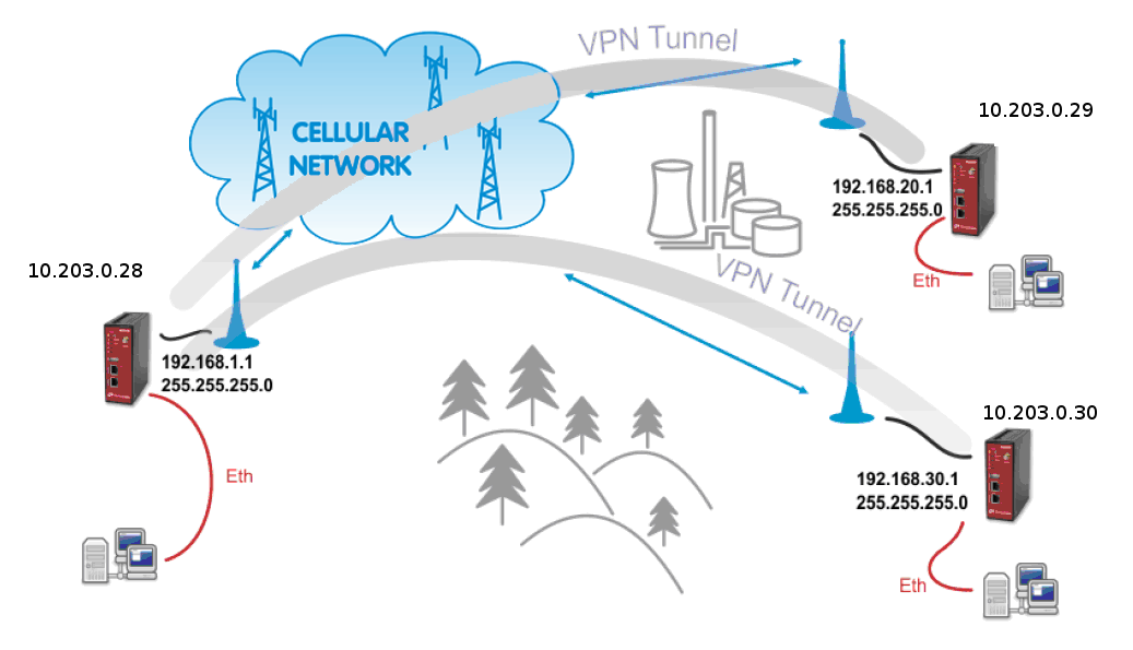
The topology for GRE tunnel example is very similar to IPsec and OpenVPN topologies. The main difference are mobile (WWAN) IP addresses. In GRE, both units are equal to each other, i.e. there are no “server” and “client” roles. One important requirement is that both ends of the tunnel must be able to access/reach the remote end mobile IP. In this example, the unit 10.203.0.28 must be able to access both 10.203.0.29 and 10.203.0.30 IP addresses; and in the same time both these units must be able to access 10.203.0.28 mobile IP address.
The following example explains the configuration of 10.203.0.28 and 10.203.0.29 M!DGE units only. If you test a second tunnel as well, there must be two GRE tunnels configured in 10.203.0.28 unit.
| Note | |
|---|---|
If you utilize a public APN, the GRE requires all the mobile IPs to be public so that they can access/reach each other. |
| Note | |
|---|---|
The maximum number of GRE tunnels is 4. |
The following example explains the TUN (tunnel, routed) version. If you need to interconnect the L2 topology, just select the “TAP” Interface type and choose a required Ethernet interface.

M!DGE 10.203.0.28
Go to the VPN – GRE – Tunnel Configuration menu and enable the “Tunnel 1”.
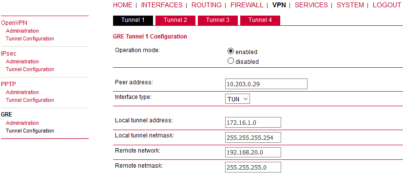
Parameters:
Peer address | “10.203.0.29” (the remote M!DGE unit’s mobile WWAN IP address) |
Interface type | “TUN” (tunnel/routed mode) |
Local tunnel address | “172.16.1.0” (the local IP address of newly created GRE tunnel) |
Local tunnel netmask | “255.255.255.254” (/31 mask in CIDR notation – only two IP addresses are required, but any wider mask is also acceptable, e.g. /30, /29, …) |
Remote network | “192.168.20.0” (remote subnet) |
Remote netmask | “255.255.255.0” (/24 mask of remote subnet) |
Click on the “Apply” button.
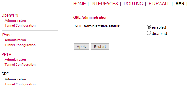
Go to the GRE Administration menu and Enable the GRE tunneling.
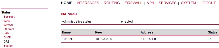
Check the Status menu – the GRE tunnel should be “up” and running. As explained, the GRE tunnel does not establish or maintain the connection and so it is “up” even though the remote end is not configured yet.
M!DGE 10.203.0.29
Go to the VPN – GRE – Tunnel Configuration menu and enable the “Tunnel 1”.
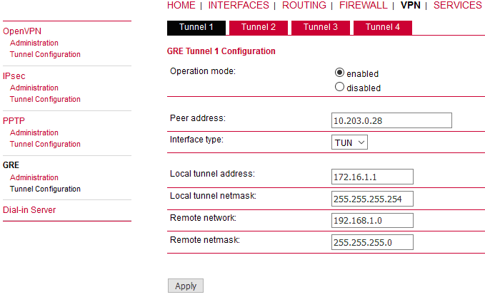
Parameters:
Peer address | “10.203.0.28” (the remote M!DGE unit’s mobile WWAN IP address) |
Interface type | “TUN” (tunnel/routed mode) |
Local tunnel address | “172.16.1.1” (the local IP address of newly created GRE tunnel) |
Local tunnel netmask | “255.255.255.254” (/31 mask in CIDR notation – only two IP addresses are required, but any wider mask is also acceptable, e.g. /30, /29, …) |
Remote network | “192.168.1.0” (remote subnet) |
Remote netmask | “255.255.255.0” (/24 mask of remote subnet) |
Click on the “Apply” button.
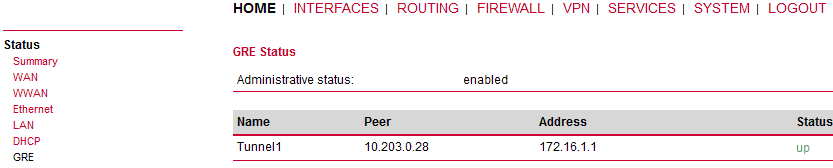
Go to the GRE Administration menu and Enable the GRE tunneling.
Check the Status menu – the GRE tunnel should be “up” and running.
The easiest way to test the GRE tunnel functionality is to run a ping command. Go to the System – Troubleshooting – Network debugging menu and fill in the remote Ethernet IP address.
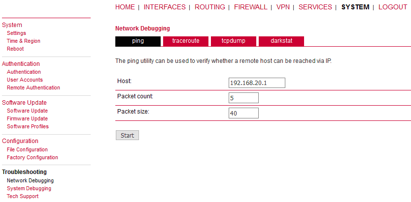
Press the “Start” button and check the results.
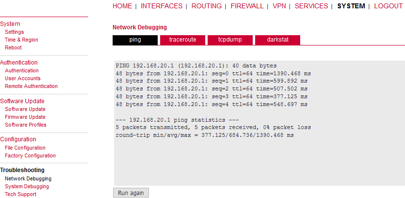
The remote IP is accessible successfully.
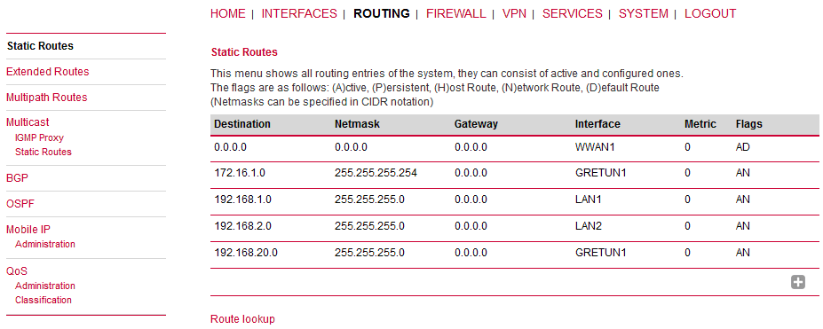
The Routing tables should be updated as well – including the configured remote subnets.
| Note | |
|---|---|
If you need to add other remote subnets, configure them in Static Routes menu – use the same GRETUN Interface and set the gateway to 0.0.0.0. |
What can be wrong if remote subnets are not accessible?
Are both remote WWAN mobile IP addresses accessible?
Is firewall turned off or configured to pass through GRE traffic?
Is the GRE network configured correctly? (IP and netmask)
Are the remote subnets configured correctly? Are Routing tables updated?
If you test the accessibility from connected PLCs/PCs, are there static routes (or default gateway) configured?