The Layer 2 Tunneling Protocol is a tunneling protocol which does not support any encryption or confidentiality. It relies on an encryption protocol that it passes within the tunnel to provide privacy. L2TPv3 is supported. Tunnel can be bridged to the local interfaces.
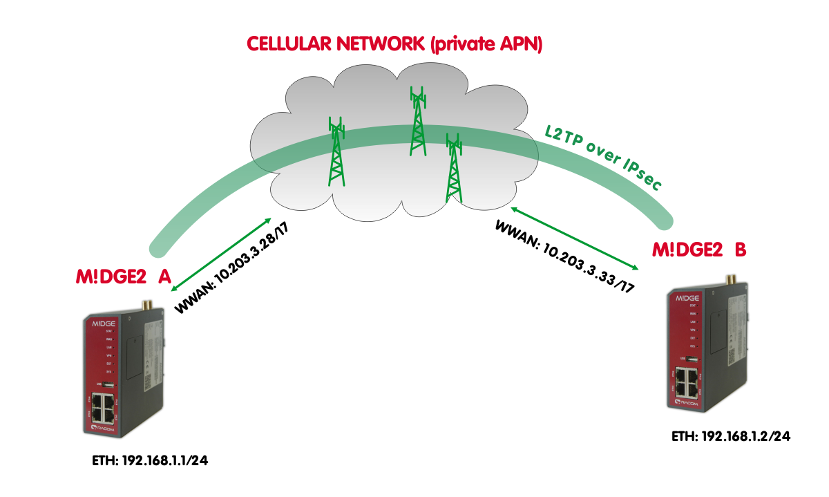
In this example, IPsec is configured to provide mentioned encryption and confidentiality. The topology is very simple, just point-to-point and connecting devices within 192.168.1.0/24 LAN subnet over M!DGE2 cellular connection (private APN).
| Note | |
|---|---|
The L2TP is supported in M!DGE2 since the FW version 4.3.40.100. |
| Note | |
|---|---|
Only L2TP and IPsec parameters are displayed and explained. Configuring private APN, ETH IP addresses etc. is not included. |
M!DGE2 A
Go to the VPN -> L2TP -> Tunnel configuration menu.
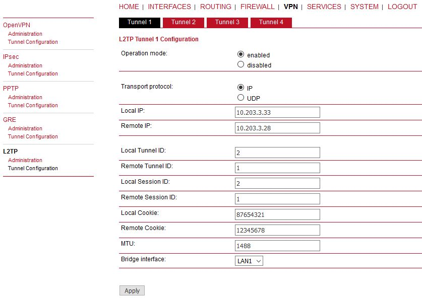
Parameters:
Operational mode | enabled |
Transport protocol | IP (default value, UDP can be better in environment with NAT and firewalls) |
Local IP | 10.203.3.28 (local WWAN IP address) |
Remote IP | 10.203.3.33 (remote WWAN IP address) |
Local Tunnel ID | 1 (L2TP tunnel numeric ID of local unit) |
Remote tunnel ID | 2 (L2TP tunnel numeric ID of remote unit) |
Local Session ID | 1 (L2TP tunnel session ID of local unit) |
Remote Session ID | 1 (L2TP tunnel session ID of remote unit) |
Local Cookie | 12345678 (optional parameter, 8digit value) |
Remote Cookie | 87654321 (optional parameter, 8digit value) |
MTU | 1488 Bytes (default) |
Bridge interface | LAN1 (the interface for which we create “pseudowire” over L2TP) |
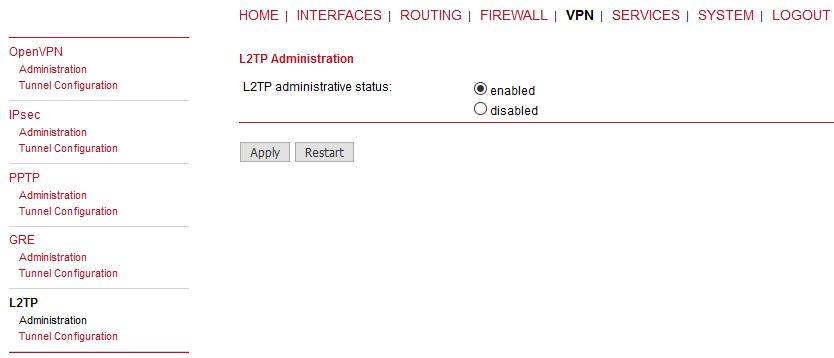
Apply the changes and enable the L2TP in Administration menu.
M!DGE2 B
Do the same configuration in B unit as well, but just switch the IPs, IDs and cookies so they match each other with A unit.
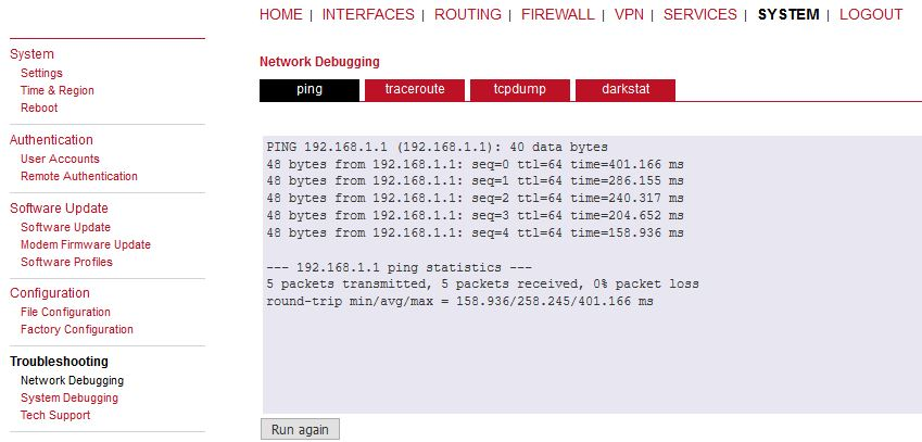
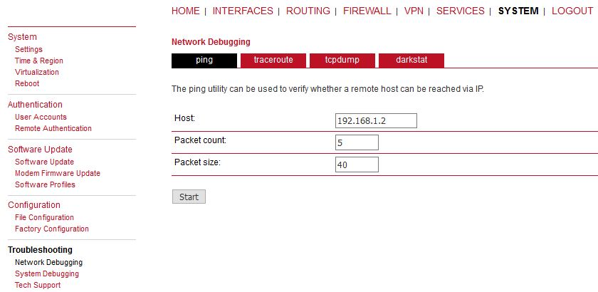
This should enable non-secure L2TP only communication between our M!DGE2 units and all devices connected via LAN1 in 192.168.1.0/24 network. You can verify the accessibility via PING tool.
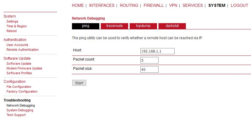
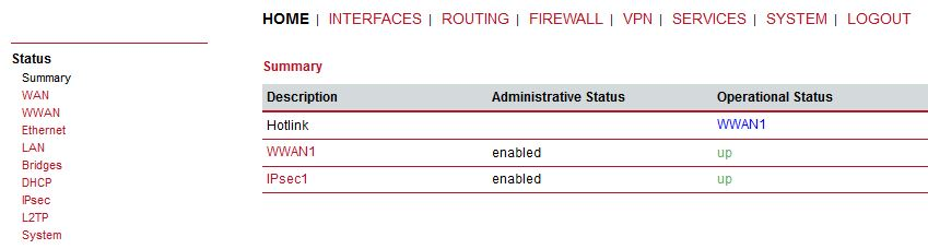
Check the results.
Go to the VPN -> IPsec -> Configuration menu and configure the IPsec tunnel.
M!DGE2 A
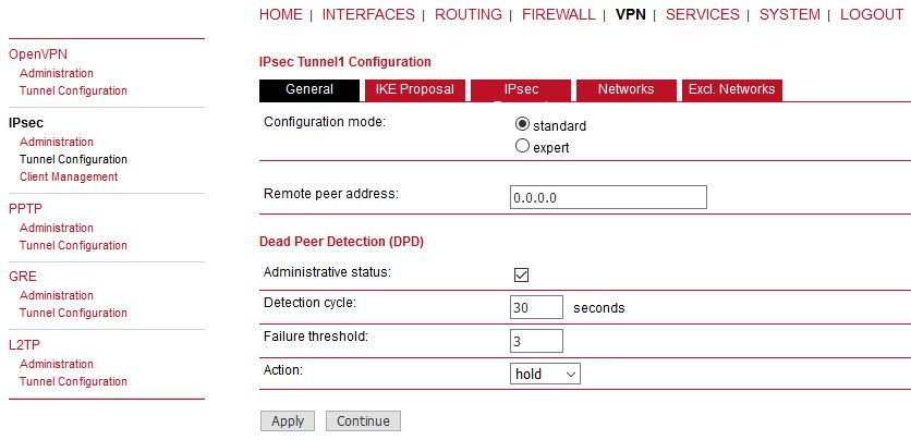
Parameters:
Remote peer address | 0.0.0.0 (passive mode) |
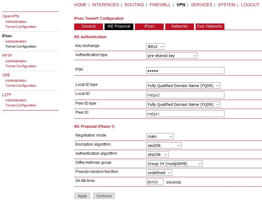
Other values can stay in default or set them as required. Set the IKE Proposal to match 2nd M!DGE2.
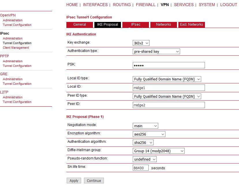
Configure the parameters as required. We configured the IKEv2 with PSK “midge”. The IDs are set to FQDN “midge1” and “midge2”. Other parameters are in default settings.
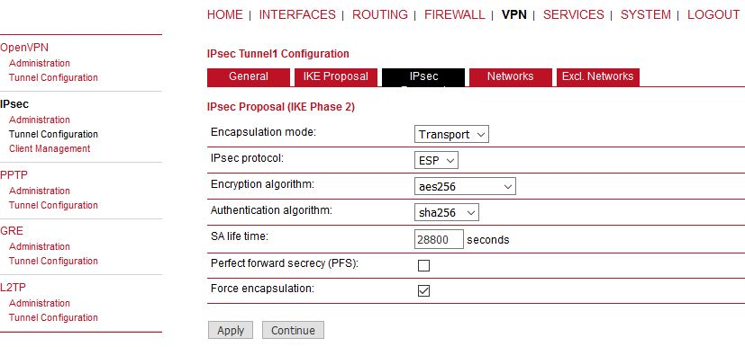
The Encapsulation mode is important. Set it to Transport mode, otherwise it will not work. The mode enables usage with other tunneling protocols such as L2TP or GRE.
Check the Force encapsulation to make sure IPsec runs over UDP.
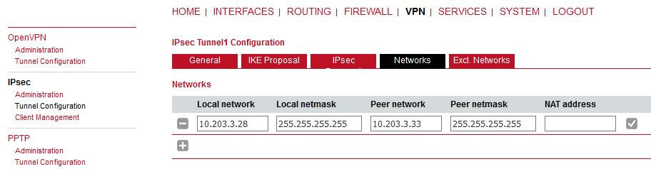
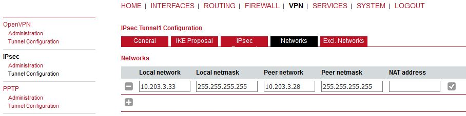
This can seem strange, but the WWAN IP addresses must be set as networks so that L2TP (or GRE) is built over IPsec – i.e. once IPsec is up, all the communication between these 2 units is via IPsec tunnel.
M!DGE2 B
Do almost the same configuration as with M!DGE2 A. See the screenshots below.
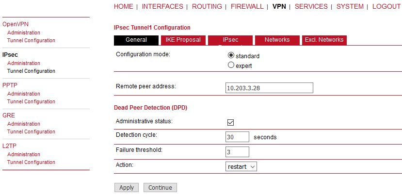
Make sure to provide correct Peer address – i.e. M!DGE A WWAN IP (10.203.3.28). The DPD action can be “restart”.
Make sure to set parameters the same as in M!DGE2 A, but with switched IDs. IPsec proposal is the same. The Networks are just switched.
Enable IPsec on both ends and wait until the tunnel is established.
Verify the remote LAN IP accessibility again.
It is not visible if it really utilizes IPsec or just L2TP. For such a purpose, capture the WWAN traffic and open the file in Wireshark application.
Start tcpdump, excluding management ports.
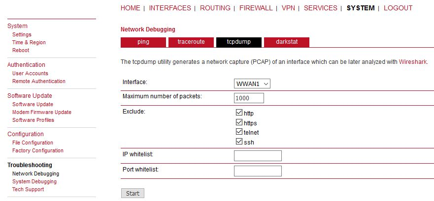
Click on the start button. Then, run the PING command in second M!DGE2 unit.
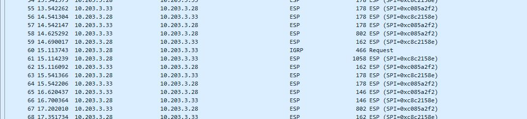
After the test finishes, download the tcpdump file. Unzip this file and open the saved file in Windows/Linux application called Wireshark. Check that most of data are ESP (i.e. IPsec encapsulated). If not, check your configuration.
GRE over IPsec
The very the same principles are used for GRE tunnel over IPsec. Configure IPsec the same way. Configure GRE tunnel for Routing purposes – it is NOT connecting Layer2 devices, but Layer3 (IP). Thus, it requires different LAN subnets at individual sites, e.g. 192.168.1.0/24 and 192.168.2.0/24.
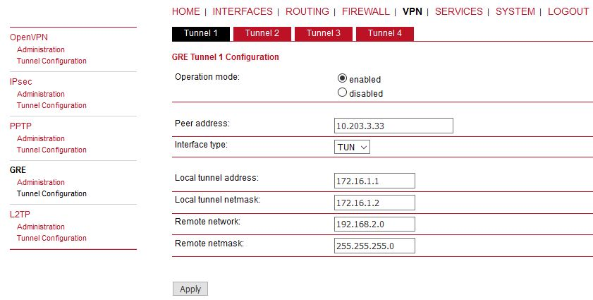
Do the opposite site the same way, just mirror the parameters. If IPsec is disabled, you should see unencrypted data on WWAN encapsulated to GRE (new network 172.16.1.x). Once IPsec is enabled, you will see ESP data again.