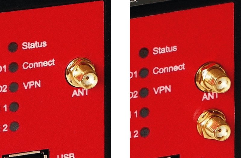
The UMTS model has one SMA antenna connector.
The LTE model is equipped with two antenna connectors. The ANT connector (above) serves as a main antenna connection, the second connector is auxiliary and serves for better communication with BTS (diversity).
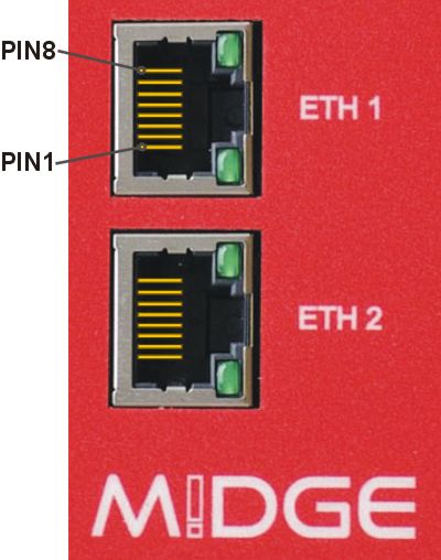
Tab. 4.1: Pin assignment Ethernet interface
| RJ-45 Socket | ETH (Ethernet 10BaseT and 100BaseT) |
|---|---|
| pin | signal |
| 1 | TX+ |
| 2 | TX− |
| 3 | RX+ |
| 6 | RX− |
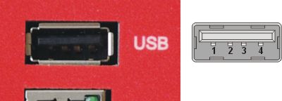
M!DGE uses USB 1.1, Host A interface. USB interface is wired as standard:
Screw terminal plug type Stelvio Kontek CPF5/15 or MRT3P/15V01 can be used.
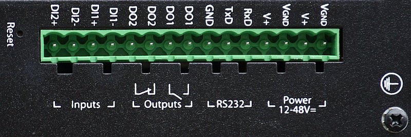
Tab. 4.3: Screw terminal pin assignment
| pin | pin description | signal |
|---|---|---|
| 1 | VGND | Ground internally connected with casing ground. |
| 2 | V+ (12–48 V=) | Dual power input – not connected with pin 4: 12–48 VDC (−15 % +20 %) = 10.2–57.6 VDC. |
| 3 | VGND | Ground internally connected with casing ground. |
| 4 | V+ (12–48 V=) | Dual power input – not connected with pin 2: 12–48 VDC (−15 % +20 %) = 10.2–57.6 VDC. |
| 5 | RxD | RS232 – RxD (receiving data) |
| 6 | TxD | RS232 – TxD (transmitting data) |
| 7 | GND | RS232 – GND (ground) |
| 8 | DO1: | Digital output. Dry contact relay. Normally open with M!DGE without powering. |
| 9 | ||
| 10 | DO2: | Digital output. Dry contact relay. Normally open with M!DGE without powering. See Section 7.2.7, “Digital I/O” for details. |
| 11 | ||
| 12 | DI1− | Digital input 1 |
| 13 | DI1+ | Digital input 1 |
| 14 | DI2− | Digital input 2 |
| 15 | DI2+ | Digital input 2 – see Section 7.2.7, “Digital I/O” |
Tab. 4.4: Digital input levels
| logical level 0 | 0 to 5.0 VDC |
| logical level 1 | 7.2 to 40 VDC |
| Note: Negative input voltage is not recognised. | |
Tab. 4.5: Digital output parameters
| Maximal continuous current | 1 A |
| Maximal switching voltage | 60 VDC, 42 VAC (Vrms) |
| Maximal switching capacity | 60 W |
Tab. 4.6: Voltage Polarity connector misconnection Risks
| pin | pin description | Plug pos. | Plug pos. | Plug pos. | Plug pos. | ||||
|---|---|---|---|---|---|---|---|---|---|
| 1 | VGND | − | OK | + | Nde | − | − | ||
| 2 | V+ (12–48 V=) | + | − | − | Nde | + | OK | ||
| 3 | VGND | − | OK | + | Nde | + | − | ||
| 4 | V+ (12–48 V=) | + | − | − | Nde | + | Nde | ||
| 5 | RxD | − | DP [1] | + | DP [1] | + | − | ||
| 6 | TxD | + | − | − | DP [1] | + | DP [1] | ||
| 7 | GND | − | Nde | + | Nde | + | − | ||
| 8 | DO1-1 | + | − | − | Nde [2] | + | Nde [2] | ||
| 9 | DO1-2 | − | Nde | + | Nde | + | − | ||
| 10 | DO2-1 | + | − | − | Nde [3] | + | Nde [3] | ||
| 11 | DO2-2 | − | Nde | + | Nde | + | − | ||
| 12 | DI1− | + | − | − | OK [4] | + | Nde [4] | ||
| 13 | DI1+ | − | Nde | + | Nde | + | − | ||
| 14 | DI2− | + | − | − | OK [4] | + | Nde [4] | ||
| 15 | DI2+ | + | − |
Explanatory notes for the table:
OK – Normal operation
DP – Damage possible
Nde
– No damage expected
[2] – If the relay is closed (normally open), the relay is damaged when current > 5 A
[3] – If the relay is closed (normally closed), the relay is damaged when current > 5 A
[4] – If the applied voltage is > 40 V, input circuit damage is likely
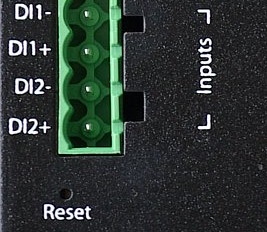
The Reset button is placed close to the screw terminal and it is labeled “Reset”. Use a blunt tool no more than 1 mm in diameter (e.g. a paper clip) to press the button.
Keep it pressed for at least 3 seconds for reboot and at least 10 seconds for a factory reset. The start of the factory reset is confirmed by all LEDs lighting up for one second. The button can be released afterwards.
| Note | |
|---|---|
If the button is being pressed at least 15 seconds until all LED diodes blink red, the recovery procedure is started. The recovery image can be provided on demand and a special procedure utilizing the TFTP transfer from your computer is required. Contact our technical support team for more details. |
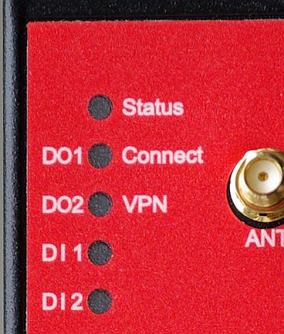
Tab. 4.7: M!DGE interfaces and status indicators
| Label | State | Function |
|---|---|---|
| Status | green blinking | Start up, maintenance |
| green on | Ready (right side banks description) | |
| orange on | Ready (left side banks description) | |
| orange blinking | Insufficient power supply | |
| Connect | blinking | Mobile connection is being established |
| on | Mobile connection is up | |
| green | Excellent GSM signal | |
| orange | Medium GSM signal | |
| red | Weak GSM signal | |
| VPN | green on | VPN connection is up |
| green blinking | VPN connection is being established | |
| If left side banks displayed | ||
| DO1 | on | Closed |
| off | Opened | |
| DO2 | on | Closed |
| off | Opened | |
| DI1 | on | Input set |
| off | Input not set | |
| DI2 | on | Input set |
| off | Input not set | |
WWAN RSSI/RSQ/ASU and LED colour
For Releases newer or equal to 4.0.40.102:
Tab. 4.8: RSSI
| Description | excellent | good | medium | weak | bad | critical | n/a |
| GSM RSSI [dBm] | -59 or more | -61 to -81 | -83 to -91 | -93 to -101 | -103 to -107 | -109 to -111 | -113 or less |
| UMTS RSSI [dBm] | -68 or more | -70 to -84 | -86 to -94 | -96 to -104 | -106 to -110 | -111 to -114 | -116 or less |
| LTE RSRQ [dB] | -49 or more | -50 to -79 | -80 to -89 | -90 to -104 | -105 to -110 | -111 to -117 | -118 or less |
Tab. 4.9: ASU
| Description | excellent | good | medium | weak | bad | critical | n/a |
| GSM | 27 or more | 26 to 16 | 15 to 11 | 10 to 6 | 5 to 3 | 2 to 1 | 0 |
| UMTS | 24 or more | 23 to 16 | 15 to 11 | 10 to 6 | 5 to 3 | 2 to 1 | 0 |
| LTE | 71 or more | 70 to 41 | 40 to 31 | 30 to 16 | 15 to 10 | 9 to 3 | 2 or less |
| Note | |
|---|---|
For LED description used in older firmware versions, see the previous manual version at www.racom.eu. |
Tab. 4.11: Technical specifications
| Mobile Interface UMTS |
| |||||||||||||||||
| Mobile Interface LTE |
| |||||||||||||||||
| Mobile Interface LTE450 |
| |||||||||||||||||
| Ethernet | 2× Ethernet 10/100 Base-T, Auto MDX, 2× RJ45, bridged or routed | |||||||||||||||||
| Serial Interface | 1× 3-wire RS232 on 15-pin screw terminal block | |||||||||||||||||
| Digital I/O | 2 digital inputs |
| ||||||||||||||||
| 2 digital outputs |
| |||||||||||||||||
| USB service interface |
| |||||||||||||||||
| Antenna Interface | Impedance: | 50 Ω | ||||||||||||||||
| Connector: | SMA female | |||||||||||||||||
| Power Supply | Input voltage: | 10.2–57.6 VDC (12–48 VDC −15 % / +20 %) | ||||||||||||||||
| Power consumption: |
| |||||||||||||||||
| Environmental Conditions |
| |||||||||||||||||
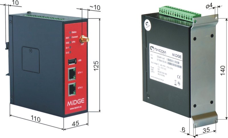
| Mounting | DIN rail mounting |
| Dimensions / Weight | 45 W × 110 D × 125 H mm (1.77 × 4.33 × 4.92 in), ca. 450 g (0.99 lbs) |
| Type Approval | CE, FCC |
| Options | |
| Antennas | Various antennas suitable for your application are available |
| Mounting kit | Flat bracket mounting kit |
M!DGE-UMTS | GPRS/EDGE/UMTS/HSPA router, 2Eth, RS232, 2DI,
2DO |
M!DGE-LTE | GPRS/EDGE/UMTS/HSPA+/LTE router, 2Eth, RS232, 2DI,
2DO |
M!DGE-LTE450 | GPRS/EDGE/UMTS/HSPA+/LTE router, 2Eth, RS232, 2DI,
2DO |
SW feature keys
The SW feature key should be added to a new or running system via adding a license: menu SYSTEM – Licensing (see Section 7.7.7, “Licensing”).
Mobile IP | This key allows building a MobileIP VPN tunnel. See WAN Backup application for short explanation. | |||||||||||||||||||||||||||
Server Licence | Tab. 4.12: Server License
|
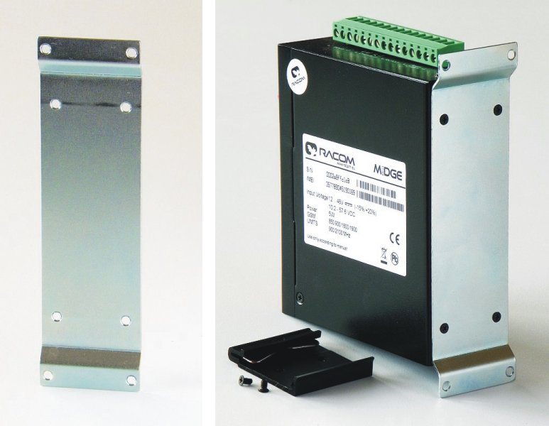
Flat-bracket
Installation bracket for flat mounting. For usage details see chapter Mounting and chapter Dimensions.
A rugged plastic case for carrying up to three RipEX units and one M!DGE SCADA router. It also contains all the accessories needed to perform an on-site signal measurement, complete application bench-test or a functional demonstration of both radio modems and the cellular router. During a field test, units can be powered from the backup battery and the external antenna can be connected to one of the RipEX units through the „N“ connector on the case.
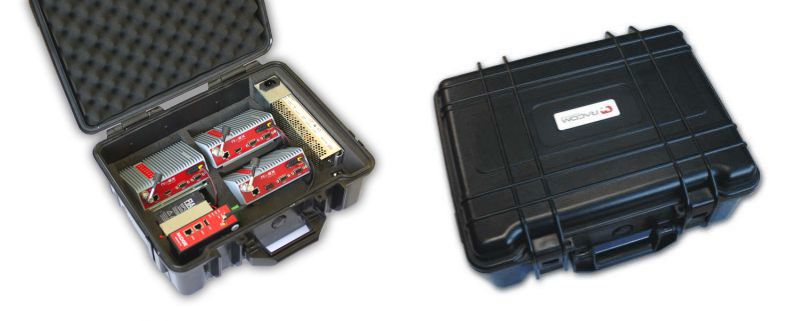
Contents:
Brackets and cabling for installation of three RipEX units and one M!DGE (units not included)
1× power supply Mean Well AD-155A (100-240 V AC 50-60 Hz/13.8 V DC)
1× Backup battery (12V/5Ah, FASTON.250), e.g. Fiamm 12FGH23
1× Power cable (European Schuko CEE 7/7 to IEC 320 C13)
1× Ethernet patch cable (3 m, UTP CAT 5E, 2× RJ-45)
Quick start guide
RipEX accessories:
3× Dummy load antennas
1× L-bracket, 1x Flat-bracket samples
1× Fan kit
1× X5 – ETH/USB adapter
M!DGE accessories:
Whip antenna (900–2100 MHz, 2.2 dBi, vertical)
External dimensions: 455 × 365 × 185 mm
Weight approx. 4 kg (excluding RipEXes and M!DGE)