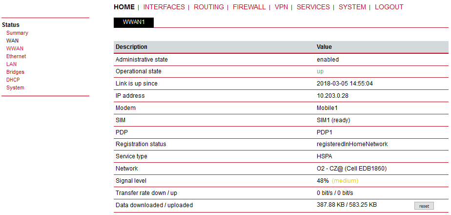
This page gives you a system overview. It helps you when initially setting up the device and also functions as a dashboard during normal operation.
The highest priority link which has been established successfully will become the so-called hotlink which holds the default route for outgoing packets.
Detailed information about status of each WAN interface is available in a separate window.
Details for all physical connections are given in Section 4.2, “Connectors”.
Each available item in the WAN Link Manager matches with the particular WAN interface. Depending on your hardware model, WAN links can be made up of either Wireless Wide Area Network (WWAN), Wireless LAN (WLAN), Ethernet or PPP over Ethernet (PPPoE) connections. Please note that each WAN link has to be configured and enabled in order to appear on this page.
In case a WAN link goes down, the system will automatically switch over to the next link in order of priority (the priorities can be changed using the arrows on the right side of the window). A link can be either established when the switch occurs or permanently to minimize link downtime.
1st priority: | This link will be used whenever possible. |
2nd priority: | The first fallback technology. |
Up to four priorities can be used.
Links are being triggered periodically and put to sleep in case it was not possible to establish them within a certain amount of time. Hence it might happen that permanent links will be dialed in background and replace links with lower priority again as soon as they got established. In case of interfering links sharing the same resources (for instance in dual-SIM operation) you may define a switch-back interval after which an active hotlink is forced to go down in order to let the higher-prio link getting dialed again.
Outgoing traffic can also be distributed over multiple links on a per IP session basis. Choose the option “distributed” as an Operation Mode with the appropriate Weight.
In the following example, the outgoing traffic will be distributed between LAN2 (80 %) and WWAN1 (20 %) links.
| Note | |
|---|---|
This option is general and applies to all outgoing traffic. See Section 7.3.3, “Multipath Routes” for more detailed configuration. |
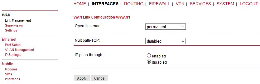
We recommend using the permanent option for WAN links. However, in case of time-limited mobile tariffs, the switchover option should be used.
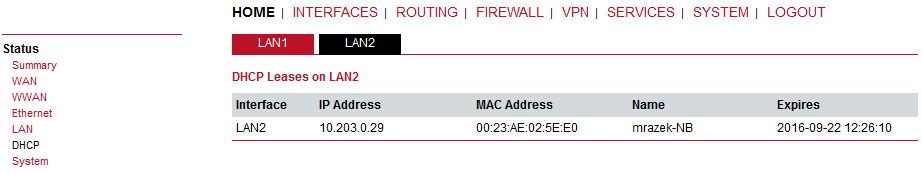
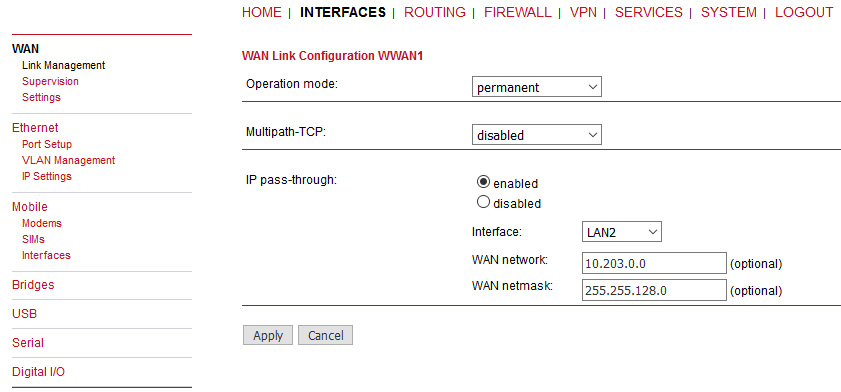
After clicking on the WWAN “Edit” button, you can additionally set the “IP passthrough” option for the selected LAN interface. The result is that the connected device over the selected LAN port will obtain M!DGE’s mobile IP address via DHCP. In another words, M!DGE will be transparent for the connected device and will only serve for the mobile connectivity. Typically, such connected device (e.g. firewall) will not need any special configuration facing M!DGE, it will just use its mobile IP address (usually the public IP address).
Once established, a small subnet containing the cellular IP is created, by default the netmask is 255.255.255.248. This small subnet consists of a network and broadcast address as a regular subnet. In some situations it may lead to unreachability of several remote hosts due to IP address overlapping. If this is the case, user can manually configure the APN network, e.g. 10.203.0.0/255.255.128.0.
In any case, the M!DGE unit is reachable via the default gateway automatically obtained from M!DGE by DHCP. The gateway IP address is set as the first available IP address after the specified APN address range. If not specified, it is the first usable IP within the /29 subnet.
| Note | |
|---|---|
We recommend to define the APN network/netmask manually. There might be situations in which the default /29 disables the communication. E.g. WWAN IP is 10.10.10.6. The connected device obtains this IP via DHCP and sets the default gateway to 10.10.10.7 – but this IP is a broadcast IP within /29 subnet and the communication is not possible. If you configure subnet 10.10.10.0/29 manually, a default gateway would be 10.10.10.8 in newly created local /28 subnet. |
Example: If the APN network is 10.203.0.0/17, the default gateway is set to 10.203.128.0. The web interface is reachable via this IP address over the selected LAN interface. The connected device’s network mask is /16 (1 bit wider), otherwise the default gateway would not be usable.
| Note | |
|---|---|
|
Network outage detection can be used for switching between available WAN links and can be performed by sending pings on each link to authoritative hosts. A link will be declared as down if all trials have failed. The link will be considered up again if at least one host is reachable.
You may further specify an emergency action if no uplink can be established at all.
Configurable actions are:
None
Restart link services
Reboot system
Link: | The WAN link to be monitored (can be ANY for all configured links). |
Mode: | Specifies whether the link is monitored during the connection establishment or only when it is already up. |
Primary host: | Reference host one which will be used for checking IP connectivity (via ICMP pings). |
Secondary host: | Reference host two which will be used for checking IP connectivity (via ICMP pings). The test is considered successful if either the primary or the secondary host answers. |
Ping timeout: | Time for which the system is waiting for the ping response. With mobile networks the response time can be quite long (several seconds) in special cases. You can check the typical response using SYSTEM – Troubleshooting – Network Debugging – Ping. The first response typically takes a longer time than the following ones in cellular networks, the Ping timeout should be set to the longer time than with the first response. |
Ping interval: | Time to wait before sending the next probe. |
Retry interval (if ping failed): | If the first trial fails, ping hosts in this modified interval until the ping is successful or the maximum number of failed trials is reached. |
Max. number of failed trials: | The maximum number of failed ping trials until the ping check will be declared as failed. |
Emergency action: | Configure the Emergency action which should be taken after the maximum downtime is reached. Using “reboot” performs the system reboot. The option “restart services” restarts all link-related applications including the modem reset. No action is done if the “none” option is set. Configure the maximum amount of downtime in minutes for which the link could not be established. |
The maximum segment size defines the largest amount of data of TCP packets (usually MTU minus 40). You may decrease the value in case of fragmentation issues or link-based limits.
MSS adjustment | Enable or disable MSS adjustment on WAN interfaces. |
Maximum segment size | Maximum number of bytes in a TCP data segment. |
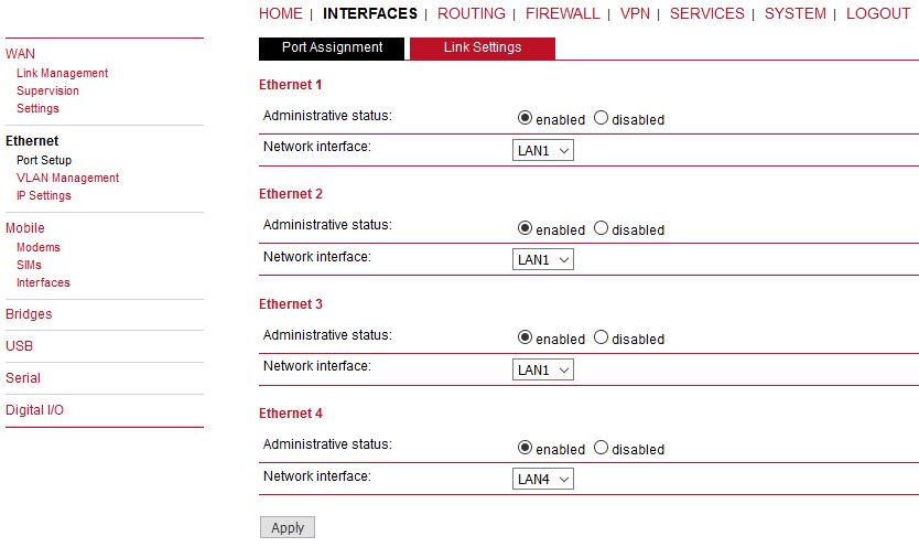
M!DGE routers ship with 4 dedicated Ethernet ports (ETH1 to ETH4) which can be linked via RJ45 connectors.
ETH1 usually forms the LAN1 interface which should be used for LAN purposes. Other interfaces can be used to connect other LAN segments or for configuring a WAN link. The LAN10 interface will be available as soon as a pre-configured USB Ethernet device has been plugged in (e.g. XA Ethernet/USB adapter).
This menu can be used to individual assigning of Ethernet ports to LAN interfaces if you want to have different subnets per port or to use one port as the WAN interface.
If it is desired to have both ports in the same LAN you may assign them to the same interface. Please note that the ports will be bridged by software and operated by running the Spanning Tree Protocol.
| Note | |
|---|---|
If USB/ETH adapter is attached and enabled, LAN10 interface is configured with 10.9.8.7/28 IP address and DHCP enabled. |
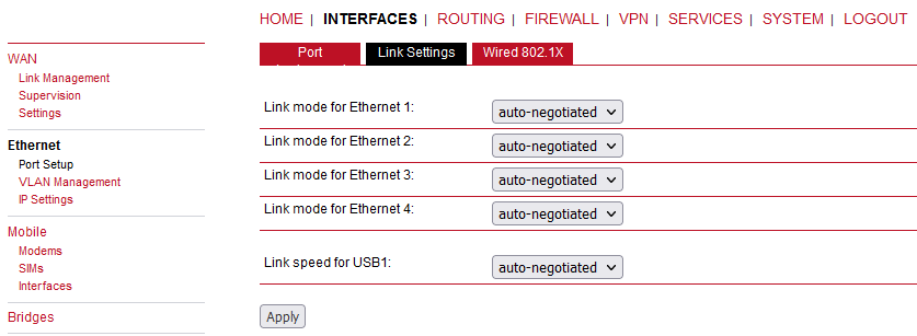
Link negotiation can be set for each Ethernet port individually. Most devices support auto negotiation which will configure the link speed automatically to comply with other devices in the network. In case of negotiation problems, you may assign the modes manually but it has to be ensured that all devices in the network utilize the same settings then.
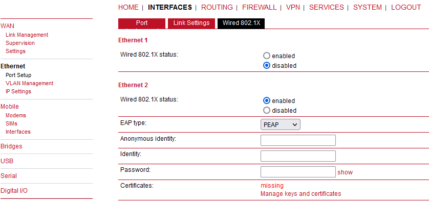
M!DGE2 supports authentication via the IEEE 802.1X standard. This can be configured for each Ethernet port individually. Current 802.1X can operate only in a “client” mode, i.e. the port can be authenticated against some external RADIUS server.
The following options exist:
Wired 802.1X status | Enable or disable IEEE 802.1X |
EAP type | Authentication protocol |
Anonymous identity | The anonymous identify for PEAP authentication |
Identity | The identify for EAP-TLS or PEAP authentication (required) |
Password | The password for PEAP authentication (required) |
Certificates | Certificates for authentication via EAP-TLS or PEAP |
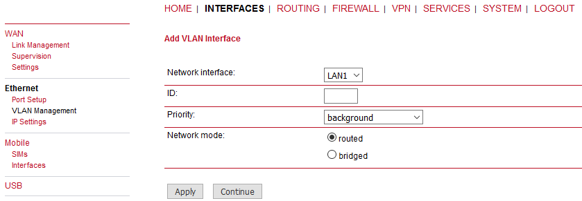
M!DGE routers support Virtual LAN according to IEEE 802.1Q which can be used to create virtual interfaces on top of the Ethernet interface. The VLAN protocol inserts an additional header to Ethernet frames carrying a VLAN Identifier (VLAN ID) which is used for distributing the packets to the associated virtual interface. Any untagged packets, as well as packets with an unassigned ID, will be distributed to the native interface. In order to form a distinctive subnet, the network interface of a remote LAN host must be configured with the same VLAN ID as defined on the router. Further, 802.1P introduces a priority field which influences packet scheduling in the TCP/IP stack.
The following priority levels (from the lowest to the highest) exist:
| Parameter | VLAN Priority Levels |
|---|---|
| 0 | Background |
| 1 | Best Effort |
| 2 | Excellent Effort |
| 3 | Critical Applications |
| 4 | Video (< 100 ms latency and jitter) |
| 5 | Voice (< 10 ms latency and jitter) |
| 6 | Internetwork Control |
| 7 | Network Control |
| Note | |
|---|---|
The maximum number of VLAN tunnels/interfaces was increased from 4 to 10 in 4.6.40.102 software. |
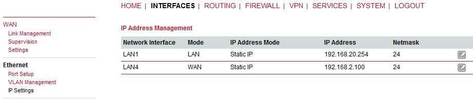
Two individual tabs will be used when different LANs are set in the Port settings menu. Each of them can be configured either in the LAN mode or in the WAN mode.
| Note | |
|---|---|
The default IP address is 192.168.1.1/24 (LAN1). |
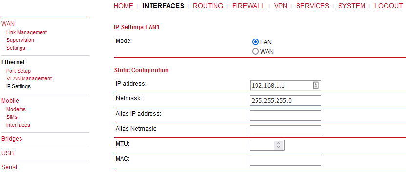
Static configuration of M!DGE’s own IP address and Subnet mask is available for the LAN mode. The Alias IP address enables configuring the LAN interface with a second IP address/subnet.
MTU: | Configure MTU of a given Ethernet interface. |
MAC: | Configure MAC address of a given Ethernet interface manually. |
| Note | |
|---|---|
Setting of the IP address is interconnected with the DHCP Server (if enabled) – menu the SERVICES – DHCP Server menu. |
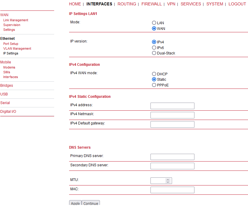
When running in WAN mode, the interface can be configured with two IP versions in the following way:
IPv4 | Only Internet Protocol Version 4. |
IPv6 | Only Internet Protocol Version 6. |
Dual-Stack | Internet Protocol Version 4 and Version 6 in parallel |
Depending on the selected IP version, you can configure your interface with the following settings:
IPv4 Settings – the router can configure its IPv4 address via:
DHCP client: | The IP configuration will be retrieved from a DHCP server in the network. No further configuration is required (you may only set MTU). | ||||||||
PPPoE: | PPPoE is the preferred protocol when communicating with another WAN access device (like a DSL modem).
| ||||||||
Static IP: | IP configuration will be set manually. At least the Default gateway and the Primary DNS server must be configured along with the IP address and subnet mask. |
IPv6 Settings – the router can configure its IPv6 address via:
SLAAC: | All IP-related settings (address, prefix, routes, DNS server) will be retrieved by the neighbor-discovery-protocol through stateless-address autoconfiguration. |
Static: | IP configuration will be set manually. At least the Primary DNS server must be configured along with the IPv6 address and Prefix length. |
| Note | |
|---|---|
You may configure MTU and MAC for any IP configuration option. |
This page lists all available WWAN modems. They can be disabled on demand. Define number of antennas to match a current physical installation.
This page allows you to send Hayes AT commands to the modem. Besides the 3GPP-conforming AT command-set, further modem-specific commands can be applied (can be provided on demand). Some modems also support running Unstructured Supplementary Service Data (USSD) requests, e.g. for querying the available balance of a prepaid account.
The SIM page gives an overview about the available SIM cards, their assigned modems and the current state. Once a SIM card has been inserted, assigned to a modem and successfully unlocked, the card should remain in state ready and the network registration status should have turned to registered. If not, please double-check your PIN.
Please keep in mind that registering to a network usually takes some time and depends on signal strength and possible radio interferences. You may hit the Update button at any time in order to restart PIN unlocking and trigger another network registration attempt.
Under some circumstances (e.g. in case the modem flaps between base stations) it might be necessary to set a specific service type or assign a fixed operator. The list of operators around can be obtained by initiating a network scan (may take up to 60 seconds). Further details can be retrieved by querying the modem directly, a set of suitable commands can be provided on request.
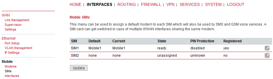
A SIM card is generally assigned to a default modem but this may switch, for instance if you set up two WWAN interfaces with one modem but different SIM cards. Close attention has to be paid when other services (such as SMS or Voice) are operating on that modem as a SIM switch will affect their operation.
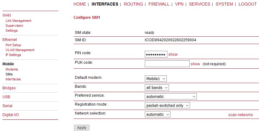
You can configure the following parameters:
PIN protection | Depending on the used card, it can be necessary to unlock the SIM with a PIN code. Please check the account details associated with your SIM whether the PIN protection is enabled. |
PIN code | The PIN code for unlocking the SIM card |
PUK code | The PUK code for unlocking the SIM card if the card was blocked due to several wrong PIN attempts. |
Default modem | The default modem assigned to this SIM card. |
Bands | The list of allowed bands to which the unit can connect. Up to four different bands for each service type (2G, 3G and 4G) can be selected. I.e., 12 in total. 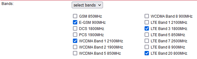 |
Preferred service | The preferred service type to be used with this SIM card. The default option is “automatic”, in areas with interfering base stations you can force a specific type (e.g. 3G-only) in order to prevent any flapping between the stations around. Preferred service type is usually set in the WWAN Interface settings, not SIM settings. Settings in WWAN interface overrides this SIM settings. |
Registration mode | The default option is set to “all networks”. You can limit the modem registration to “packet-switched only” (e.g. no Dial-in Server) or “circuit-switched only” option, which can be for example used for the Dial-in Server so one can use PPP over the Circuit-Switched Networks (analog modem style). |
Network selection | LAI is a globally unique number that identifies the country, network provider and
LAC of any given location area. It can be used to force the modem to register to a
particular mobile cell in case of competing stations. 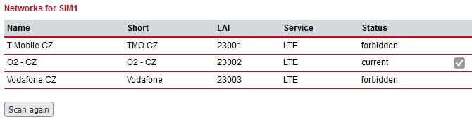 |
This page can be used to manage your WWAN interfaces. The resulting link will pop up automatically on the WAN Link Management page once an interface has been added. The Mobile LED will be blinking during the connection establishment process and goes on as soon as the connection is up. Refer to the troubleshooting section or log files in case the connection did not come up.
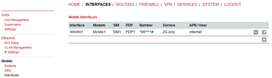
The following mobile settings are required:
Modem | The modem to be used for this WWAN interface |
SIM | The SIM card to be used for this WWAN interface |
Preferred service | The preferred service type |
Please note that these settings supersede the general SIM based settings as soon as the link is being dialed.
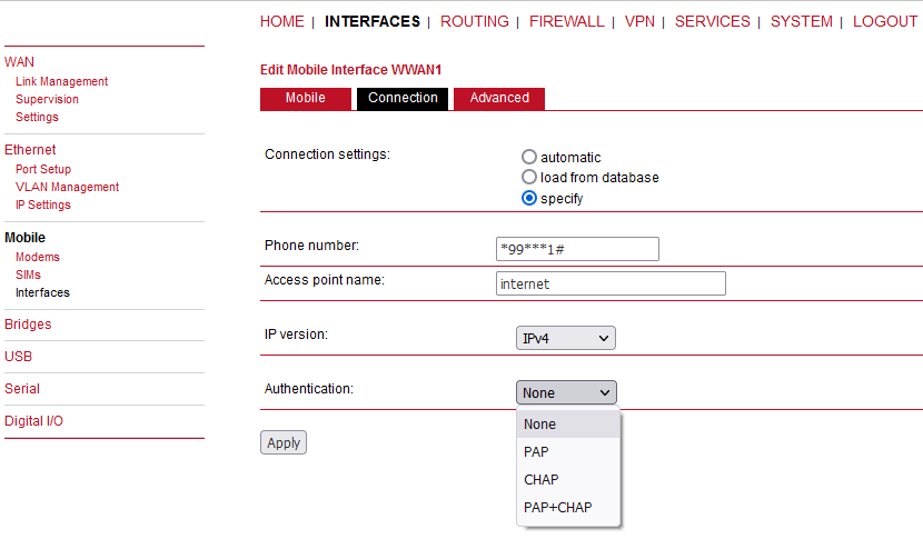
Generally, the connection settings are derived automatically as soon as the modem has been registered and the network provider has been found in our database. Otherwise, it will be required to configure the following settings:
Phone number | The phone number to be dialed, for 3G+ connections this commonly refers to be *99***1#. For circuit switched 2G connections you can enter the fixed phone number to be dialed in the international format (e.g. +420xx). |
Access point name | The access point name (APN) being used |
IP version | Select IPv4, IPv6 or Dual-stack option for your WWAN interface. Dual-stack lets you use IPv4 and IPv6 in parallel. Please note that your provider might not support all IP versions. |
Authentication | The authentication scheme being used, if required this can be PAP or/and CHAP |
Username | The username used for authentication |
Password | The password used for authentication |
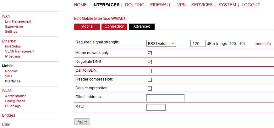
Further on, you may configure the following advanced settings:
Required signal strength | The minimum required signal strength before the connection is dialed. It can be specified as the RSSI level in dBm units, or as the Quality level in percent. See the “more info” button to see the exact values. |
Home network only | Determines whether the connection should only be dialed when registered to the home network. |
Negotiate DNS | Specifies whether the DNS negotiation should be performed and the retrieved name-servers should be applied to the system. |
Call to ISDN | This option must be enabled in case of 2G connections talking to an ISDN modem. |
Header compression | Enables or disables Van Jacobson TCP/IP Header Compression for PPP-based connections. This feature will improve TCP/IP performance over slow serial links. Has to be supported by your provider. |
Data compression | Enables or disables the data compression for PPP-based connections. Data compression reduces the packet size to improve throughput. Has to be supported by your provider. |
Client address | Specifies a fixed client IP address on the mobile interface. |
MTU | The Maximum Transmission Unit represents the largest amount of data that can be transmitted within one IP packet and can be defined for any WAN interface. |
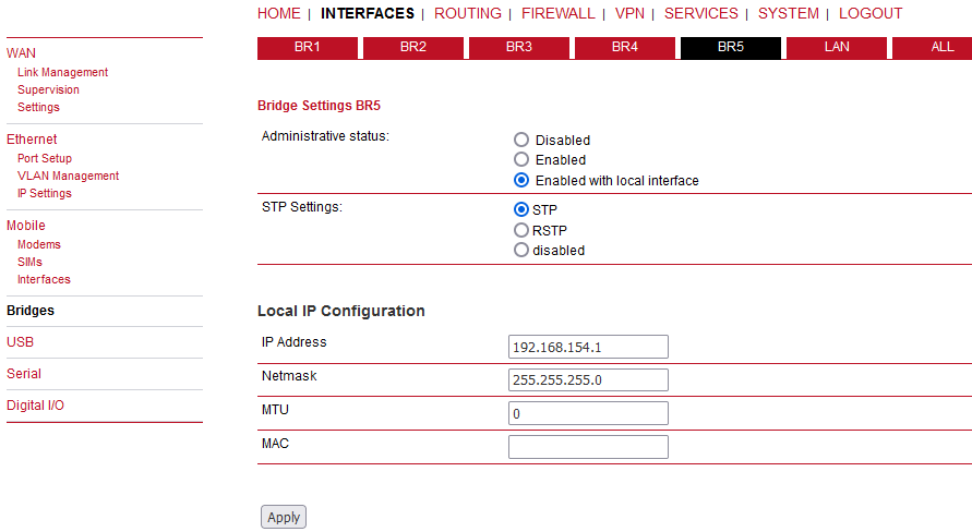
Software bridges can be used to bridge layer-2 devices like OpenVPN TAP, GRE or L2TP interfaces without the need for a physical LAN interface.
Administrative status | Enable (with/without local interfaces) or disable software
bridges. |
IP Address | IP address of the local interface (available only if “Enabled with local interface” was selected) |
Netmask | Netmask of the local interface (available only if “Enabled with local interface” was selected) |
MTU | Optional MTU size for the local interface (available only if “Enabled with local interface” was selected) |
STP Settings | You can enable or disable STP/RSTP on each Bridge interface. |
Enable bridge network filtering | If enabled, the firewall rules will also match packets between the ports. Selectable from the “ALL” panel of Bridges menu. |
LAN | You can enable or disable STP/RSTP on LAN interfaces individually and/or use a Global STP/RSTP settings for all LAN interfaces. |
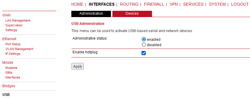
USB administration cannot be disabled. Any supported USB converter can be attached and configured for example as another serial link (RS232, see Section 7.2.6, “Serial Port”). Another typical usage is the management access via USB/ETH Adapter Axago XA or XR. The same as for RipEX and RAy devices.
| Note | |
|---|---|
Supported modules are pl2303, ch341, ftdi (quad-channel adapter), asix, pegasus and rndis. |
Following parameter can be configured:
Enable hotplug (always enabled)
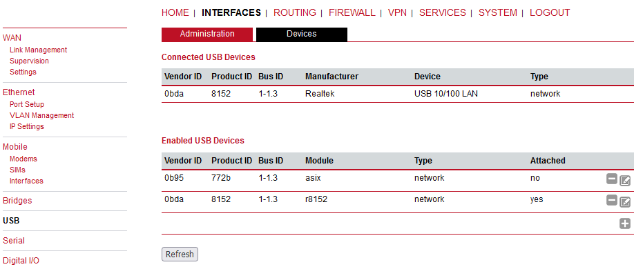
Click on the Refresh button in the tab Devices for displaying connected USB devices and add them with by clicking on the plus sign.
The serial protocol can function in various ways, configure it using the Edit button on the right. If the USB Administration is enabled, an extra SERIAL2 (USB) is available.
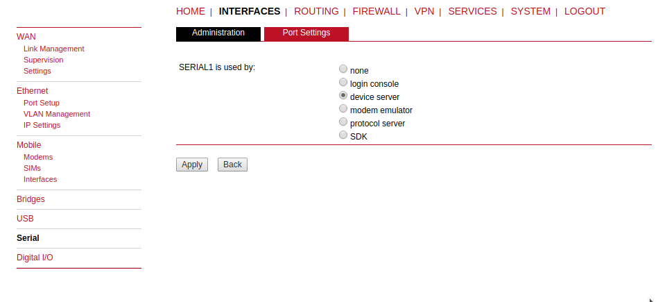
Five possibilities are available:
None | The serial port is not used at all. |
Login console | A possibility to control the unit via the CLI commands when connected to the serial port (115200 8N1). There are no extra configuration parameters. |
Device server | Use this option to control the serial device via IP (transmit the data over the cellular network, …). See the details below. |
Modem bridge | Direct connection between the LTE modem tty and the serial interface. |
Modem emulator | Replacement for legacy dial-in / dial-out connections based on analog or GSM modems (AT commands support). |
Protocol server | Special implementation of various serial protocols like Modbus, IEC101, DNP3, …(available for the primary RS232 interface only). See the details below. |
SDK | This option enables controlling the serial interface via the SDK scripts (similar to C programming). See chapter SDK for more details. |
Configure the required RS232 parameters.
| |||||||||||||||
Server |
|
| Important | |
|---|---|
The UDP Device Server functionality has been moved into SDK only. The required script for this functionality can be provided on demand. |
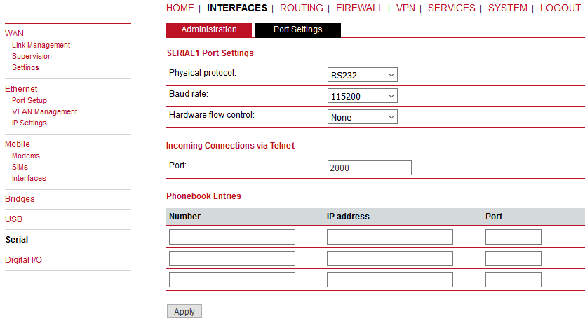
Modem emulator enables replacement for legacy dial-in / dial-out connections based on analog or GSM modems. M!DGE supports the Hayes AT Command set on the serial interface and behaves like a regular router.
You can easily replace your old Modem with M!DGE. There is also no need to configure the attached device as you can prepare the M!DGE accordingly.
Physical protocol | RS232 |
Baud rate | Specifies the baud rate of the RS232 port. |
Hardware flow control | While 3 wired connection is used with M!DGE hardware flow control is not available. |
Port | Any incoming connection will be received on the Port configured. This Port needs to be allowed, keep this in mind for Firewall configurations. |
The Phonebook configuration will keep the aliases of any Phone numbers so that you do not need to reconfigure your device and can use the original addressing scheme.
Number | Remote phone number. |
IP address | Remote IP address. |
Port | Remote port number. |
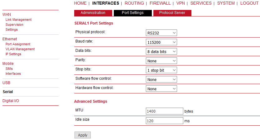
The port settings configuration is the same as with the Device Server – Section 7.2.6.1, “Device Server” except the Advanced settings called MTU and Idle size.
| Note | |
|---|---|
More details in the Serial SCADA Protocols application note. |
MTU
An incoming frame is closed at this size even if the stream of bytes continues. Consequently, a permanent data stream coming to the serial interface results in a sequence of MTU-sized frames sent over the network. The default value is set to 1400 bytes.
Idle size
Received frames on COM are closed when the gap between bytes is longer than the Idle value. This parameter defines the maximum gap (in milliseconds) in the received data stream. If the gap exceeds this value, the link is considered idle, the received frame is closed and forwarded to the network.
The default Idle size differs based on the serial baud rate configuration. Remember that the default Idle sizes are set to the minimal possible values:
| bps | ms |
|---|---|
| 115200 | 120 |
| 57600 | 60 |
| 38400 | 30 |
| 19200 | 20 |
| 9600 | 10 |
| 4800 | 5 |
| 2400 | 5 |
| 1200 | 5 |
| 600 | 5 |
| 300 | 5 |
Each SCADA protocol like Modbus, DNP3, IEC101, DF1 etc. has its unique message format, most importantly its unique way of addressing the remote units. The following text is valid for all M!DGE/RipEX units (further in this Section 7.2.6.3, “Protocol Server” referred to as a “Unit”) – the special properties for mobile cellular networks (e.g. limitation of broadcasting) are mentioned here. The basic task for the protocol server is to check whether a received frame is within the protocol format and is not corrupted. Most of the SCADA protocols are using some type of Error Detection Code (Checksum, CRC, LRC, BCC, etc.) for data integrity control, so each Unit calculates this code and checks it against the received one.
Cellular mobile network operates in IP environment, so the basic task for the Protocol server is to convert SCADA serial packets to UDP datagrams. The Address translation settings are used to define the destination IP address and UDP port. Then these UDP datagrams are sent to the M!DGE router, processed there and are forwarded as unicasts through the mobile network to their destination. When the gateway defined in the Routing table belongs to the Ethernet LAN, UDP datagrams are instead forwarded to the Ethernet interface. After reaching the gateway, the datagram is forwarded according to the Routing table.
When the UDP datagram reaches its final IP destination, it should be in a M!DGE or RipEX router again. It is processed further according to its UDP port. It can be delivered to the Protocol server where the datagram is decapsulated and the data received on the serial interface of the source unit are forwarded to COM. The UDP port can also be that of a Terminal server (RipEX) or any other special protocol daemon on Ethernet like Modbus TCP etc. The datagram is then processed according to the respective settings.
| Note | |
|---|---|
All timeouts in the parameters described below are derived from the time when the packet is sent into the COM driver, i.e. it includes the transfer time of the packet. Take this into account especially when there is a low Baud rate set in the COM settings. |
| Important | |
|---|---|
If configuring the Protocol server together with VPN tunnels the “Poll response control” protocol specific parameter must be turned off. |
| Important | |
|---|---|
Only one Protocol server can be configured and utilized only on the primary RS232 interface (it is not supported on the COMIO RS232/485 interface). This 2nd COM port can be controlled by Device server or SDK functionality. |
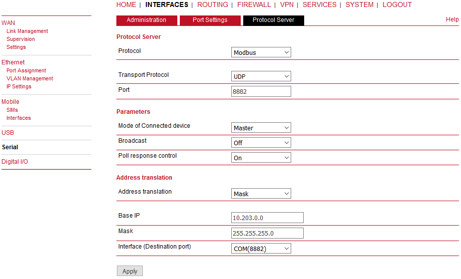
For any SCADA protocol, the Transport protocol and the specific port can be chosen. The default values is UDP port 8882. The unit listens on this port for incoming messages and forwards them to the Protocol server itself.
| Note | |
|---|---|
Only UDP protocol is currently implemented. |
The parameters described in this section are typical of most
protocols.
There is only a link to them in description of
the respective Protocol.
Mode of Connected
device
List box: Master, Slave
Default
= Master
The typical SCADA application follows the
Master–Slave scheme where the structure of the message is different for
the Master and Slave SCADA units. Because of that, it is necessary to
set which type of SCADA unit is connected to the Unit.
| Important | |
|---|---|
For the SCADA Master, set Master, for the SCADA Slave, set Slave. |
Master
The SCADA Master always sends addressed messages to Slaves. Addressing is different for each SCADA protocol, so this is one of the main reasons why an individual Protocol server in each Unit for each SCADA protocol has to be used.Broadcast
List box: On, Off
Default = Off
Some Master SCADA units send broadcast messages to all Slave units. SCADA applications typically use a specific address for such messages. RipEX (Protocol utility) converts such messages into a customized IP broadcast and broadcasts it to all RipEX units resp. to all SCADA units within the network.![[Note]](/images/radost/images/icons/note.png)
Note Broadcasts in the cellular network are not possible, thus setting of broadcast functionality is not allowed with M!DGE units.
If On, the address for broadcast packets in the SCADA protocol has to be defined:
Broadcast address format – List box Hex, Dec – format in which the broadcast address is defined.
Broadcast address – address in the defined format (Hex, Dec)
Address translation
List box: Table, Mask
Default = Mask
In a SCADA protocol, each SCADA unit has a unique address, a “Protocol address”. In a cellular mobile network, each SCADA unit is represented by an IP address (typically that of the ETH interface) and a UDP port (that of the protocol daemon or the COM port server to which the SCADA device is connected via serial interface).
A translation between the “Protocol address” and the IP address & UDP port pair has to be done. It can be done either via Table or Mask.
Hence, a SCADA message received from the serial interface is encapsulated into a UDP/IP datagram, where the destination IP address and the destination UDP port are defined according to the settings of the Address translation.Translation using the Mask is simpler to set, however it has some limitations:
− all IP addresses used have to be within the same network, which is defined by this Mask
−the same UDP port is used for all the SCADA units, which results in the following:Base IP
Default = IP address of the ETH interface
When creating the IP destination address of UDP datagram, in which the serial SCADA message received from COM is encapsulated, this is created, this Base IP is taken as the basis and only the part defined by the Mask is replaced by the ‘Protocol address’.Mask
Default = 255.255.255.0
A part of the Base IP address defined by this Mask is replaced by the ‘Protocol address’. The SCADA protocol address is typically 1 byte, so Mask 255.255.255.0 is most frequently used.UDP port (Interface)
List box: COM, Manual
This UDP port is used as the destination UDP port in the UDP datagram in which the serial SCADA packet received from COM1 is encapsulated. The default UDP port for COM can be used or the UDP port can be set manually. If the destination IP address belongs to a Unit and the UDP port is not assigned to COM (COM1(2) or to a Terminal server in case of RipEX) or to any special daemon running in the destination address, the packet is discarded.Note M!DGE use UDP port 8882 for its COM port.
Table
The Address translation is defined in a table. There are no limitations such as when the Mask translation is used. If there are more SCADA units on the RS485 (e.g. with RipEX COM2) their interface, their “Protocol addresses” should be translated to the same IP address and UDP port pair, where the multiple SCADA units are connected. There are 3 possibilities how to fill in the line in the table:
− One “Protocol address” to one “IP address” (e.g.: 56 −−> 192.168.20.20)
− Range of “Protocol addresses” to one “IP address” (e.g.: 56 – 62 ===> 192.168.20.20)
− Range of “Protocol addresses” to range of “IP addresses” (e.g.: 56 – 62 ===> 192.168.20.20 – 26). One option is to write only the start IP and a dash, the system will add the end address itself.Protocol address
This is the address which is used by the SCADA protocol. It may be set either in Hexadecimal or Decimal format according to the List box value.
Protocol address length can be 1 byte, but for the DNP3 and UNI protocols support 2 bytes addresses.IP
The IP address to which Protocol address will be translated. This IP address is used as the destination IP address in the UDP datagram in which serial SCADA packet received from COM is encapsulated.UDP port (Interface)
This is the UDP port number which is used as the destination UDP port in the UDP datagram in which the serial SCADA message, received from COM, is encapsulated.Note
You may add a note to each address up to 16 characters long for your convenience. (E.g. “Remote unit #1”).Active
You may tick/un-tick each translation line in order to make it active/not active.Modify
Edit, Delete Add buttons allow to edit or to add or to delete a line. The lines can be sorted using up and down arrows.
The SCADA Slave typically only responds to Master requests, however in some SCADA protocols it can communicate spontaneously.
Messages from the serial interface are processed in a similar way as the Master site, i.e. they are encapsulated in UDP datagrams, processed by the router inside the M!DGE unit and forwarded to the respective interface, typically to the mobile network.
Within several protocols, parameter “Poll response control” can be set. Turn it off if using any kind of port forwarding or VPN tunnels. Otherwise, it can be set to “On”. More details about this parameter can be found at UNI protocol description.
The async link creates asynchronous link between two COM ports on different Units. Received frames from COM are sent without any processing transparently to the mobile network to set the IP destination and UDP port. Received frames from the mobile network are sent to the respective COM according to the UDP port setting.
Parameters
Destination IP
This is the IP address of the destination Unit.UDP port (Interface)
This is the UDP port number which is used as the destination UDP port in the UDP datagram in which the packet received from COM is encapsulated.
C24 is a serial polling-type communication protocol used in Master–Slave applications.
Multiple C24 Masters can be used within one network and one Slave can be polled by more than one Master.
Italicised parameters are described in Common parameters.
Protocol frames
List box: 1C, 2C, 3C, 4C
Default = 1C
One of the possible C24 Protocol frames can be selected.Frames format
List box: Format1, Format2, Format3, Format4, Format5
Default = Format1
One of the possible C24 Frames formats can be selected. According to the C24 protocol specification, it is possible to set Frames formats 1–4 for Protocol frames 1C–3C and formats 1–5 for 4C.![[Important]](/images/radost/images/icons/important.png)
Important The Unit accepts only the set Protocol frames and Frames format combination. All other combinations frames are discarded by the Unit and not passed to the application.
Local ACK
List box: Off, On
Default = Off
Available for Protocol frame 1C only. When On, ACK on COM is send locally from this unit, not over the mobile network.
Cactus is a serial polling-type communication protocol used in
Master–Slave applications.
Multiple Cactus Masters can be
used within one network and one Slave can be polled by more than one
Master.
Italicised parameters are described in Common parameters.
| Mode of Connected device | |||
| Master | |||
| Broadcast | |||
| Note: There is no the possibility to set Broadcast address, since Cactus broadcast messages always have the address 0x00. Hence when the Broadcast is On, packets with this destination are handled as broadcasts. Broadcasting is not supported with mobile networks. | |||
| Address translation | |||
| Table | |||
| Mask | |||
| Slave | |||
| Broadcast accept | |||
Max gap timeout [ms]
Default = 30
The longest time gap for which a frame can be interrupted and still received successfully as one frame. It should not be set below 10ms, while 15–40 ms should be OK for a typical Cactus protocol device.
Comli is a serial polling-type communication protocol used by
Master–Slave applications.
More Comli Masters can be used
within one network and one Slave can be polled by more
Masters.
Broadcasts packets are not used, so the
configuration is using only some parameters described in Common parameters.
Only the full-duplex mode of DF1 is supported. Each frame in the Allen-Bradley DF1 protocol contains the source and destination addresses in its header, so there is no difference between Master and Slave in the full-duplex mode in terms of Unit configuration.
Block control mode
List box: BCC, CRC
Default = BCC
According to the DF1 specification, either BCC or CRC for Block control mode (data integrity) can be used.Broadcast
According to the DF1 specification, packets for the destination address 0xFF are considered broadcasts. Broadcasts are not supported with the mobile network.
Advanced parameters
ACK Locally
List box: Off, On
Default = On
If “On“, ACK frames (0x1006) are not transferred over-the-air.
When the Unit receives a data frame from the connected device, it generates the ACK frame (0x1006) locally. When the Unit receives the data frame from the mobile network, it sends the frame to the connected device and waits for the ACK. If the ACK is not received within 1 sec. timeout, Unit sends ENQ (0x1005). ENQ and ACK are not generated for broadcast packets.
Each frame in the DNP3 protocol contains the source and destination addresses in its header, so there is no difference between Master and Slave in terms of the M!DGE configuration. The DNP3 allows both Master–Slave polling as well as spontaneous communication from remote units.
Broadcast – Note: There is not the option to set the Broadcast address, since DNP3 broadcast messages always have addresses in the range 0xFFFD – 0xFFFF. Broadcasting is not supported by mobile networks, thus it is not possible to set the broadcast to On..
IEC 870-5-101 is a serial polling-type communication protocol used
by Master–Slave application.
More IEC 870-5-101 Masters can
be used within one network and one Slave can be polled by more
Masters.
IEC 870-5-101 protocol configuration is using all
parameters described in Common
parameters.
| Mode of Connected device | |||
| Master | |||
| Broadcast – only On, Off. Protocol broadcast address is not configurable, it is defined by Address mode in Advance parameter (default 0xFF), but broadcasting is not allowed within mobile networks. | |||
| Address translation | |||
| Table | |||
| Mask | |||
| Slave | |||
| Broadcast accept | |||
Advanced parameters
Address mode
Even if IEC 870-5-101 is the standard, there are some users who have customized this standard according to their needs. If addressed byte has been moved, M!DGE/RipEX has to read it at the correct frame position.IEC101
Address byte location according to IEC 870-5-101 standard.
Broadcast from Master station is generated when address byte is 0xFF.2B ADDR
Two byte address (IEC 870-5-101 standard is 1 byte). The frame is 1 byte longer than the standard one. There is the Intel sequence of bytes: low byte, high byte. Mask Address translation has to be used, because Table one is limited to just one byte address length.
The Master station broadcast is generated when the low address byte is 0xFF and high address byte is also 0xFF.TELEGYR
The Control byte in the standard IEC packet is omitted. The frame is 1 byte shorter than a standard one. This is typically used in the Telegyr 805/809 protocol.
Broadcast from Master station broadcast is generated when the address byte is 0x00.SINAUT
The sequence of Address byte and Control byte in the frame is swapped-over.
Master station broadcast is generated when the address byte is 0x00.
ITT Flygt is a serial polling-type communication protocol used in Master–Slave applications.
ITT Flygt protocol configuration uses all parameters described in Common parameters.
| Mode of Connected device | |||
| Master | |||
| Broadcast | |||
Note: There is no possibility to set the Broadcast address, since ITT Flygt broadcast messages always have the address 0xFFFF. Hence when the Broadcast is On, packets with this destination are handled as broadcasts. Broadcasting is not available with mobile cellular networks.
| |||
| Address translation | |||
| Table | |||
| Mask | |||
| Slave | |||
| Broadcast accept | |||
Wait timeout [ms]
Default = 5000
An ITT Flygt Slave sometimes sends the WAIT COMMAND (0x13) to its Master. The Unit does not accept the next WAIT COMMAND (discards it), till the Wait timeout expires. The Recommended value is in the 1–10 seconds range.
Modbus RTU is a serial polling-type communication protocol used by
Master–Slave application.
More Modbus Masters can be used
within one network and one Slave can be polled by more
Masters.
Modbus protocol configuration uses all parameters
described in Common
parameters.
RipEX supports Profibus DP (Process Field Bus, Decentralized Periphery) the widest-spread version of Profibus. The Profibus DP is supported even by M!DGE, but it will work satisfactorily only with mobile networks with very short transport delays, like LTE or UMTS. The Profibus protocol configuration uses all parameters described in Common parameters.
RP570 is a serial polling-type communication protocol used in Master–Slave applications.
Multiple RP570 Masters can be used within one network and one Slave can be polled by more than one Master.
Italicised parameters are described in Common parameters.
Local simulation RB
List box: Off, On
Default = Off
The RP570 protocol Master very often transmits the RB packets (hold packets) solely to check whether Slaves are connected. In order to minimize the mobile network payload, the Unit can be configured to respond to these packets locally and not to transmit them to the Slaves over the mobile network.If On, the Unit responds to RB packets received from the RP 570 master locally over the COM interface. However from time to time (RB period) the RB packets are transferred over the network in order to check whether the respective Slave is still on. When the RB response from the Slave to this RB packet is not received over the mobile network within the set RB timeout, i.e. the respective Slave is out of order, the central Unit stops local answering to RB packets from the master for the respective Slave.
RB Net period [s]
Default = 10
The M!DGE/RipEX responds to the RB packets locally and in the set RB period the RB packets are transferred over the network.RB Net timeout [s]
Default = 10 (maximum=8190)
Whenever an RB packet is sent over the network, the set RB Net timeout starts. When the RB response from the remote unit (Slave) is not received within the timeout, i.e. the respective Slave is out of order, the central Unit stops the local answering to RB packets from the master for the respective Slave.
Local simulation RB
List box: Off, On
Default = Off
The RP570 Slave expects to receive RB packets from the Master. When the Local simulation RB on the Master is On, the RB packets are transferred over the mobile network only in the RB Net period (see the Master settings). The Local simulation RB has to be set the same (On or Off) on all sites in the network, i.e. on the master as well as all Slaves.If On, the Unit generates RB packets locally and transmits them over the COM interface in the RB Request period and expects the RB response for each RB packet from the RP570 Slave within the RB Response timeout. When the Unit does not receive the response(s) from the RP570 Slave, the Unit does not respond to the RB packet from the Master, which it receives over the mobile networks.
RB Request period [ms]
Default = 200 (maximum=8190)
M!DGE/RipEX sends locally RB packets to the connected RTU in the set period.RB Response timeout [ms]
Default = 500 (maximum=8190)
The Unit expects a response to the RB packet within the set timeout. If it is not received, the Unit does not respond to RB packets from the Master received over the mobile network.RTU address (Hex)
Default = 01
Active only when the Local simulation RB is On. The connected RTU’s address is supposed to be filled in. This address (0x00-0xFF) is used in the RB packets generated locally in the M!DGE/RipEX and transmitted over the COM.
The 3964 protocol is utilized by the Siemens Company as a Point-to-Point connection between two controllers. Meanwhile it has become an industry standard that can be found on many devices as a universal communications interface. 3964R is the same as 3964, in addition it only uses BCC (Block Check Character). 3964(R) handle only the link layer (L2 in OSI model), hence Unit uses a similar way to read “SCADA address” as in UNI protocol.
There is a handshake STX(0x02) – DLE(Ox10) at the start of communication and DLE+ETX – DLE at the end. This handshake is performed by M!DGE/RipEX locally, it is not transferred over the network.
Communication goes as follows:
LocalRTU→STX→LocalRipex
LocalRipex→DLE→LocalRTU
LocalRTU→DATA+DLE+ETX+BCC→LocalRipex
LocalRipex→DATA→RemoteRipex*
LocalRipex→DLE→LocalRTU
RemoteRipex→STX→RemoteRTU
RemoteRTU→DLE→RemoteRipex
RemoteRipex→DATA+DLE+ETX+BCC→RemoteRTU
RemoteRTU→DLE→RemoteRipex
* only this packet is transferred over the RipEX network, all the other ones are handled locally.
Italicised parameters are described in Common parameters.
| Mode of Connected device | |||
| Master | |||
| |||
| Broadcast | |||
| Address translation | |||
| Table | |||
| Mask | |||
| Slave | |||
| Broadcast accept | |||
DLE timeout [ms]
Default = 1000 (min. 300, max. 8190)M!DGE/RipEX expects a response (DLE) from the connected device (RTU) within the set timeout. If it is not received, the Unit repeats the frame according to the “Retries” setting.
Retries [No]
Default = 3 (min. 0, max. 7)When DLE timeout is „On“, and the DLE packet is not received from the connected device (RTU) within the set DLE timeout, the Unit retransmits the frame. The number of possible retries is specified.
Priority
List box: Low, High
Default = LowWhen the equipment sends STX and receives STX instead of DLE, there is a collision, both devices want to start communication. In such a case, one unit has to have priority. If the Priority is High, the Unit waits for DLE. When it is Low, the Unit send DLE.
Note: Obviously, two devices which are communicating together must be set so that one has High priority and the other has Low.
BCC
List box: On, Off
Default = OnBCC (Block Check Character) is a control byte used for data integrity control, it makes the reliability higher. BCC is used by 3964R, 3964 does not use it.
The unit checks (calculates itself) this byte while receiving a packet on COM. Unit transmits DLE (accepts the frame) only when the check result is OK. The BCC byte is not transferred over the network, it is calculated locally in the end Unit and appended to the received data.
UNI is the “Universal” protocol utility designed by RACOM. It is supposed to be used when the application protocol is not in the Unit list. The key condition is that messages generated by the Master application device always contain the respective Slave address and that address (or its relevant part) position, relative to the beginning of the message (packet, frame), is always the same (Address position).
Generally two communication modes are typical for the UNI protocol: In the first one, communication always has to be initiated by the Master and only one response to a request is supported; in the second mode, Master-Master communication or combination of UNI protocol with ASYNC LINK protocol and spontaneous packet generation on remote sites are possible.
The UNI protocol is fully transparent, i.e. all messages are transported and delivered in full, without any modifications.
Italicised parameters are described in Common parameters.
| Mode of Connected device | |||
| Master | |||
| |||
| Broadcast | |||
| Address translation | |||
| Table | |||
| Mask | |||
| Slave | |||
| Broadcast accept | |||
The Digital I/O page displays the current status of the I/O ports and can be used to turn output ports on or off.
You can apply the following settings:
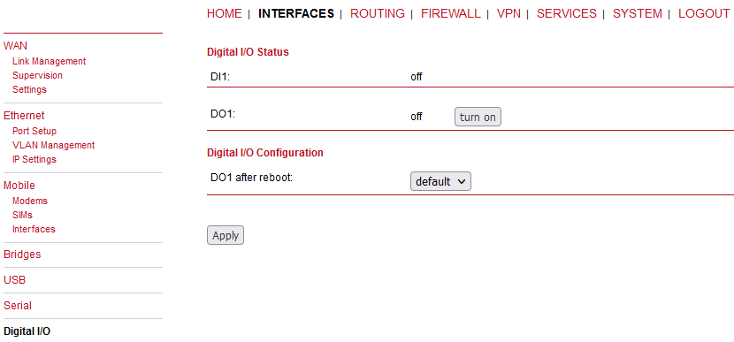
Besides on and off you may keep the status after reboot at default which corresponds to the default state as the hardware will be initialized at power-up.
The digital inputs and outputs can also be monitored and controlled by SDK scripts.
Specification:
Receiver | 72-channel GPS/QZSS L1 C/A, GLONASS L10F, BeiDou B1I, Galileo E1B/C, SBAS L1 C/A: WAAS, EGNOS, MSAS, GAGAN |
Data stream | JSON or NMEA |
Tracking sensitivity | up to -162 dBm |
Supported antennas | active |
The GNSS antenna port have the following specification:
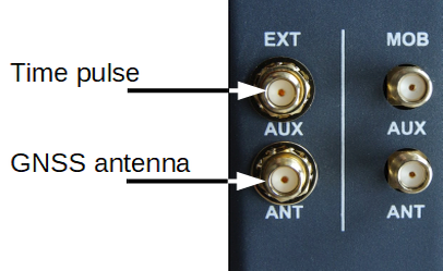
Max. allowed cable length | 30m |
Max. allowed antenna gain | 3.0 dBi |
Min. distance between collocated radio transmitter antennas (e.g.: GNSS to LTE) | 20cm |
Connector type | SMA |
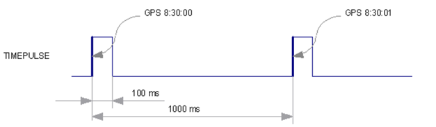
Time pulse | TTL logic (L: 0 to 0.8 V, H: 2 to 3.3 V), minimal connected load 100 Ω |
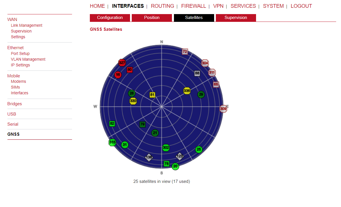
GNSS status
This pages provides further information about the satellites in view and values derived from them:
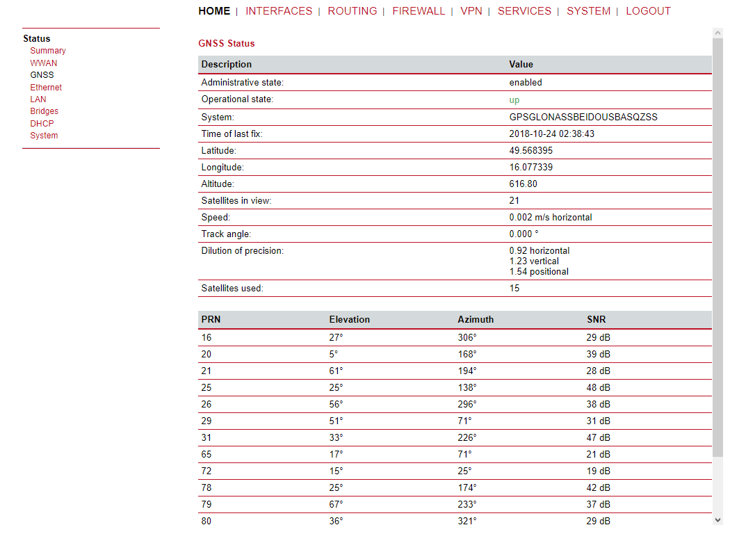
Latitude | The geographic coordinate specifying the north-south position |
Longitude | The geographic coordinate specifying the east-west position |
Altitude | The height above sea level of the current location |
Satellites in view | The number of satellites in view as stated in GPGSV frames |
Speed frames | The horizontal and vertical speed in meter per second as stated in GPRMC |
Satellites used frames | The number of satellites used for calculating the position as stated in GPGGA |
Dilution of precision | The dilution of precision as stated in GPGSA frames further on, each satellite also comes with the following details: GNSS satellite information |
PRN frames | The PRN code of the satellite (also referred as satellite ID) as stated in GPGSA |
Elevation stated in GPGSV frames | The elevation (up-down angle between the dish pointing direction) in degrees as stated in GPGSV frames |
Azimuth frames | The azimuth (rotation around the vertical axis) in degrees as stated in GPGSV |
SNR | The SNR (Signal to Noise Ratio), often referred as signal strength |
| Note | |
|---|---|
Please note that the values are shown as calculated by the daemon, their accuracy might be suggestive. |
Administration
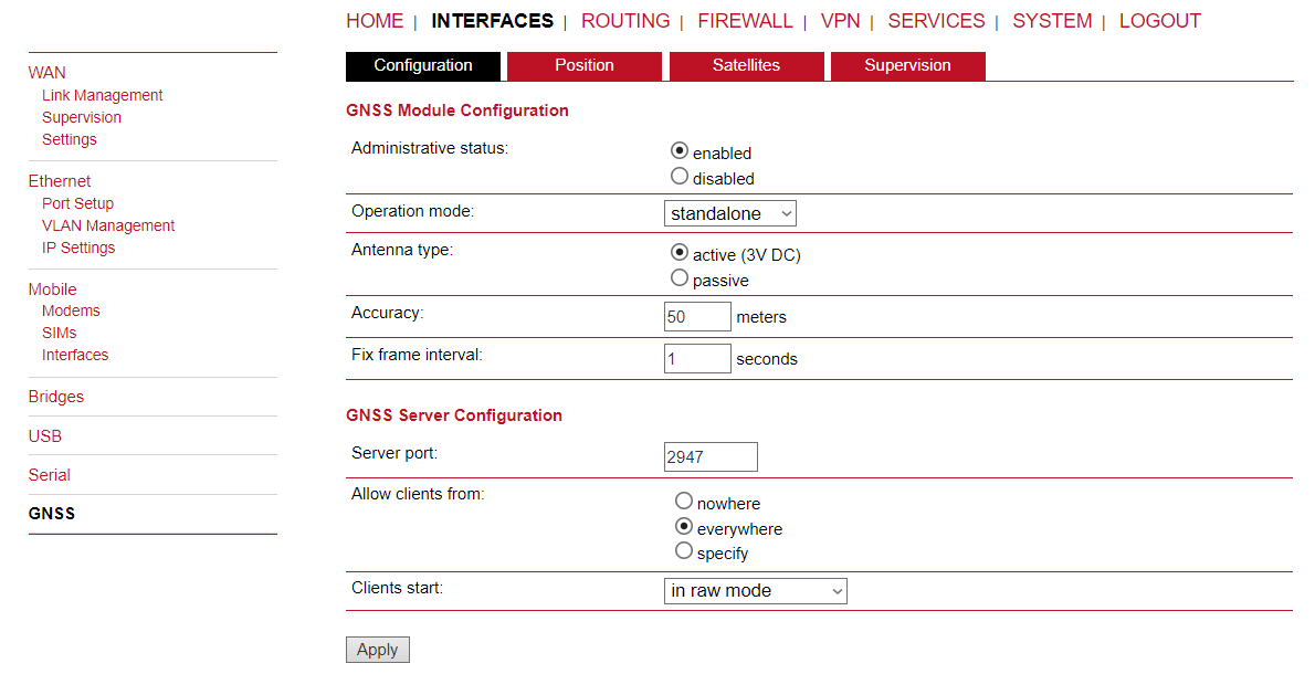
The GNSS page lets you enable or disable the GNSS modules present in the system and can be used to configure the daemon that can be used to share access to receivers without contention or loss of data and to respond to queries with a format that is substantially easier to parse than the NMEA 0183 emitted directly by the GNSS device.
We are currently running the Berlios GPS daemon (version 3.15), supporting the new JSON format. Please navigate to http://www.catb.org/gpsd/ for getting more information about how to connect any clients to the daemon remotely. The position values can also be queried by the CLI and used in SDK scripts.
GNSS Module Configuration
Administrative status | Enable or disable the GNSS module
|
GNSS Server Configuration
Server port | The TCP port on which the daemon is listening for incoming connections |
Allow clients from | Specifies where clients can connect from, can be either everywhere or from a specific network |
Clients start mode | Specifies how data transferal is accomplished when a client connects. You can specify on request which typically requires an R to be sent. Data will be sent instantly in case of raw mode which will provide NMEA frames or super-raw which includes the original data of the GPS receiver. If the client supports the JSON format (i.e. newer libgps is used) the json mode can be specified. |
| Note | |
|---|---|
Please consider to restrict access to the server port, either by a specifying a dedicated client network or by using a firewall rule. |
Satellites
Supervision
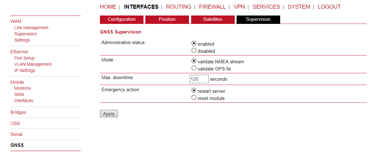
GNSS supervision
Administrative status | Enable or disable GNSS supervision |
Mode | Specifies whether to monitor the NMEA stream or GPS fixes |
Max. downtime | The period of time without valid NMEA stream or GPS 1x after which an emergency action shall be taken |
Emergency action | The corresponding emergency action. You can either let just restart the server, which will also re-initialize the GPS function on the module, or reset the module in severe cases. Please note that this may have effects on any running WWAN/SMS services. |
This menu shows all routing entries of the system, which can consist of active and
configured ones. (Netmasks can be specified in CIDR notation, e.g. 24 expands to 255.255.255.0).

Destination: | Destination network or host provided by IP addresses in dotted decimal. | ||||||||||
Netmask: | Subnet mask which forms, in combination with the destination,
the network to be addressed. A single host can be specified by a
netmask of | ||||||||||
Gateway: | The next hop which operates as gateway for this network (can be omitted on peer-to-peer links). | ||||||||||
Interface: | Network interface on which a packet will be transmitted in order to reach the gateway or network behind. | ||||||||||
Metric: | The routing metric of the interface (default 0). The routing metric is used by routing protocols, higher metrics have the effect of making a route less favourable; metrics are counted as additional costs to the destination network. | ||||||||||
Flags: | (A)ctive, (P)ersistent, (H)ost Route, (N)etwork Route, (D)efault Route The flags obtain the following meanings:
|
You can check the corresponding routing via the “Route lookup” functionality. Just fill in the desired IP address and click on the “Lookup” button. The detailed information about the chosen route will be displayed.
| Note | |
|---|---|
The maximum number of manual static routes is 10. This number can be increased to 30 with a SERVER licence. |
Extended routes can be used to perform policy-based routing, they generally precede static routes.
Extended routes can be made up not only of a destination address/netmask but also a source address/netmask, incoming interface and the type of service (TOS) of packets.
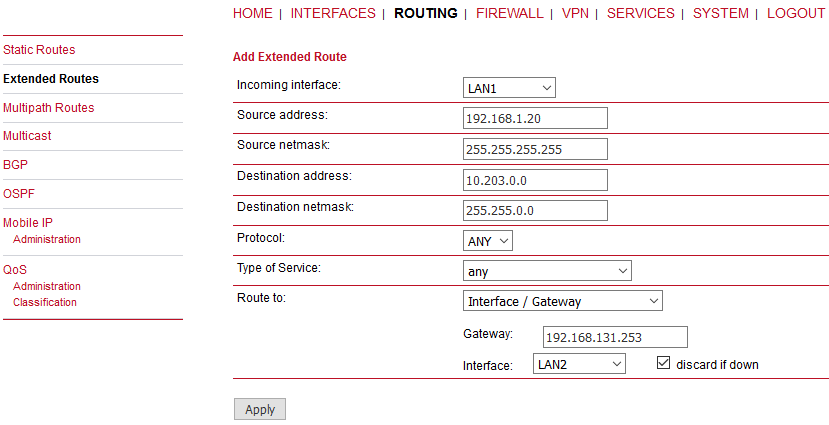
Incoming interface | The interface on which the packet enters the system |
Source address | The packet source address |
Source netmask | The packet source netmask |
Destination address | The packet destination address |
Destination netmask | The packet destination netmask |
Protocol | Protocol used (ANY, UDP or TCP) |
Type of Service | The ToS value within the packet header (possible values are any, normal-service (0), minimize-cost (2), maximize-reliability (4), maximize-throughput (8), minimize-delay (16)) |
Route to | Specifies the target interface or gateway to where the packet should get routed to. Check the “discard if down” option for discarding data if the Interface is down (e.g. nothing is connected). |
Multipath routes perform weighted IP-session distribution for particular subnets across multiple interfaces.
At least two interfaces must be defined to establish the Multipath routing. Additional interfaces can be added by pressing the “plus” sign.
Target network/netmask | The target network for which the Multipath routing will be applied |
Interface | The interface for the selected path |
Weight | Interface weight in relation to the others (e.g. values 4 and 1 for two paths will result in 80 and 20 % of distribution) |
Nexthop | Nexthop address to be used as a default gateway for the selected interface |
Multicast routing (MCR) can be configured and managed by a daemon. Only one MCR daemon can be used at a time.
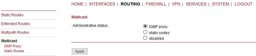
M!DGE routers ship with two different MCR daemons to select from, depending on your dependencies:
IGMP proxy | Forwarding of multicast messages that are dynamically detected on a given interface to another interface. |
Static routes | List of MCR rules to forward messages of dedicated source and group from a given interface to another. |
Disabled | Disable routing of multicast messages. |
IGMP proxy
IGMP proxy which is able to maintain multicast groups on a particular interface and distribute incoming multicast packets towards the downstream interfaces on which hosts have joined the groups.
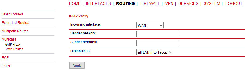
Administrative status | Specifies whether multicast routing is active. |
Incoming interface | The upstream interface on which multicast groups are joined and on which multicast packets come in. |
Distribute to | Specifies the downstream interfaces to which multicast packets will be forwarded. |
Static Routes
Routes multicast messages in different directions depending on their origin and group based on a given set of MCR rules:
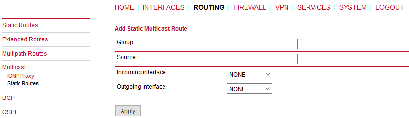
Group | IP address of MCR group. |
Source | Source-IP of the packets. |
Incoming interface | Interface to listen on for messages of given group and source. |
Outgoing interface | Interface to forward the messages to. |
The BGP tab allows to set up peerings of the M!DGE router with other Border Gateway Protocol enabled routers.
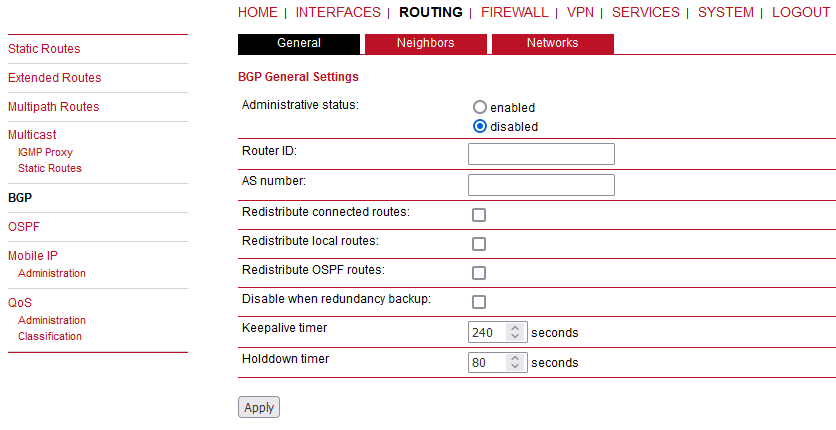
BGP status | Specifies whether the BGP routing protocol is active. |
Router ID | Every router is identified by an ID having the format of IP address. This IP address does not have to be ‘real’. If no Router ID is specified, the system will automatically choose the highest IP address as the Router ID. |
AS number | The number of the autonomous system to which the M!DGE router belongs (available range: 1 – 4294967295). |
Redistribute connected routes | Redistribute routes to networks which are directly connected to the M!DGE router. |
Redistribute local routes | Redistribute routes from the M!DGE router’s own routing table. |
Redistribute OSPF routes | Redistribute routes learned via the OSPF routing protocol. |
Disable when redundancy backup | Disables the BGP protocol when the router is set to slave mode by the VRRP redundancy protocol. |
Keepalive timer | When M!DGE has no ‘update’ messages to send, it periodically sends ‘keepalive’ messages, which keep the BGP session alive. (Default: 240 seconds. Available range 3 – 10800.) |
Holddown timer | The hold time specifies how long M!DGE waits for incoming BGP messages before it assumes the neighbor is dead. (Default: 80 seconds. Available range 1 – 3600.) |
The neighbors tab is used to configure all the BGP routers to peer with.
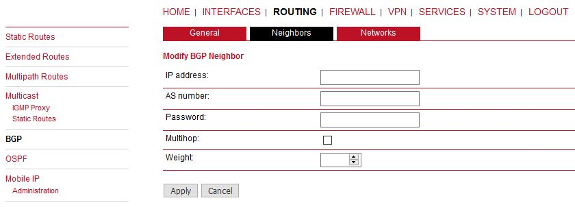
IP address | IP address of the peer router. |
AS number | Autonomous system number of the peer router (available range 1 – 4294967295). |
Password | Password for authentication with the peer router. If left blank authentication is disabled. |
Multihop | Allow multiple hops between this router and the peer router instead of requiring the peer to be directly connected. |
Weight | Weight is a simple number in the range of 0 through 65535, and the higher the weight value, the higher the preference for that path. Default: 0 |
The Networks tab allows to add IP network prefixes that shall be distributed via BGP in addition to the networks that are redistributed from other sources as defined on the general tab.
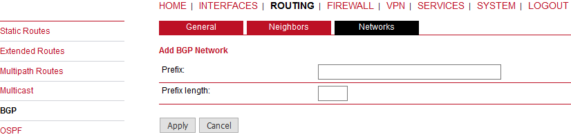
Prefix | Prefix of the network to be distributed. |
Prefix length | Length of the prefix to be distributed. |
The OSPF tab allows the M!DGE router to be added to a network of OSPF routers.
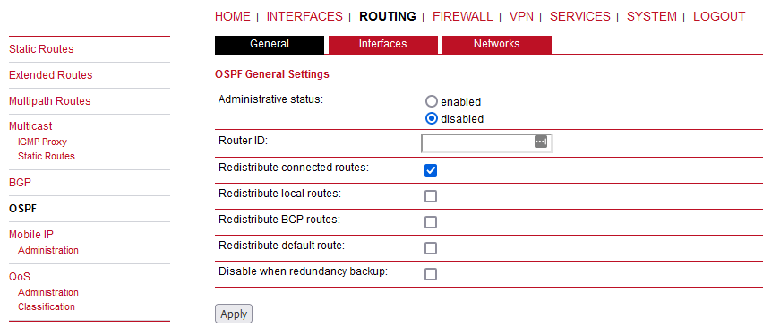
OSPF status | Specifies whether the OSPF routing protocol is active. |
Router ID | Every router is identified by an ID having the format of IP address. This IP address does not have to be ‘real’. If no Router ID is specified, the system will automatically choose the highest IP address as the Router ID. |
Redistribute connected routes | Redistribute routes to networks which are directly connected to the M!DGE router. |
Redistribute local routes | Redistribute routes from the M!DGE router’s own routing table. |
Redistribute BGP routes | Redistribute routes learned via the BGP routing protocol. |
Redistribute default route | Redistribute the routers default route. |
Disable when redundancy backup | Disables the OSPF protocol when the router is set to slave mode by the VRRP redundancy protocol. |
The interfaces tab is used to define OSPF specific settings for the IP interfaces of the router. If no settings are defined for a specific interface, default settings will be used.
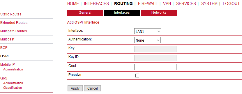
Interface | The name of the interface for which settings shall be defined. |
Authentication | The authentication protocol to be used on the interface to authenticate OSPF packets. |
Key | The key to be used for authentication. |
Key ID | The ID of the key to be used for authentication (1-255). |
Cost | The cost for sending packets via this interface. If not specified or set to 0, OSPF defaults are used. |
Passive | Do not send out OSPF packets on this interface. |
The networks tab defines the IP networks to be handled in OSPF as well as to which routing area they belong.
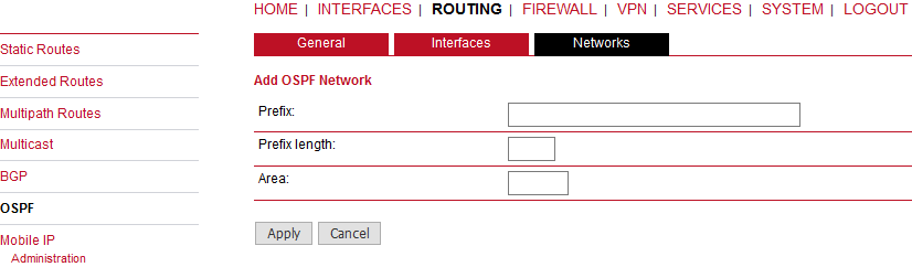
Prefix | Prefix of the network. |
Prefix length | Length of the prefix. |
Area | Routing area to which this interface belongs (0-65535, 0 means backbone). |
Mobile IP (MIP) can be used to enable a seamless switch between different WAN technologies.
It boasts with very small outages during switchover while keeping all IP sessions alive which is being accomplished by communicating with the static public IP address of a home agent which will encapsulate the packets and send them further to the router. Switching works by telling the home agent that the hotlink address has changed, the agent will then re-route (that means encapsulate the packets with the new target address) the packets transparently down to the box.
Our implementation supports RFC 3344, 5177, 3024 and 3519 and interoperability with Cisco has been verified. However, M!DGE routers can run as node and home agent which makes them able to replace expensive kits in the backbone for smaller scenarios.
If MIP is run as the Mobile node, the following settings can be configured:
Primary home agent address: | The address of the primary home agent |
Secondary home agent address: | The address of the secondary (fallback) home agent |
Home address: | The permanent home address of the node which can be used to address the box |
SPI: | The Security Parameter Index (SPI) identifying the security context between a pair of nodes (represented in 8 chars hex) |
Authentication type: | The used authentication, can be prefix-suffix-md5 or hmac-md5 |
Shared secret: | The shared secret used for authentication, can be a 128-bit hex or ASCII string |
Life time: | The lifetime of security associations in seconds |
MTU: | Maximum transmission unit in bytes |
UDP encapsulation: | Specifies whether UDP encapsulation shall be used |
Mobile network address: | Optionally specifies a subnet which should be routed to the box |
Mobile network mask: | The netmask for the optional routed network |
If MIP is run as home agent, you will have to set up a home address and netmask first and configure various nodes afterwards which are made up of the following settings:
SPI | The home address of the network |
Authentication type | The mask for the home network. |
Shared secret | The shared secret used for the mobile node authentication at the home agent. This can be either a 128-bit hexadecimal value or a random length ASCII string. |
M!DGE routers are able to prioritize and shape certain kinds of IP traffic. This is currently limited on egress, which means that only outgoing traffic can be stipulated. The current QoS solution is using Stochastic Fairness Queueing (SFQ) classes in combination with Hierarchy Token Bucket (HTB) qdiscs. Its principle of operation can be summarized as ceiling the max. throughput per link and shaping traffic by reflecting the specified queue priorities. In general, the lowest priority number of a queue gets most out of the available bandwidth.
In case of demands for other class or qdisc algorithms please contact our support team in order to evaluate the best approach for your application.
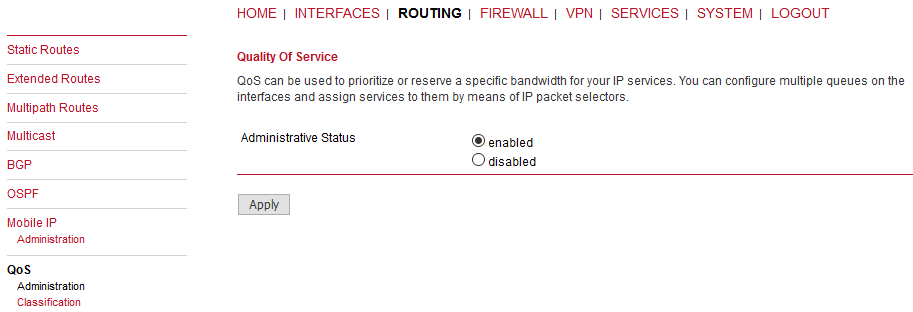
QoS Administration
The administration page can be used to enable and disable QoS.
QoS Classification
The classification section can be used to define the WAN interfaces on which QoS should be active.
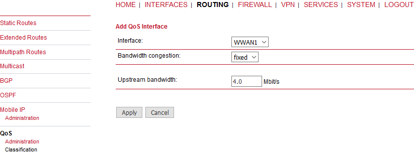
Interface: | The WAN interface on which QoS should be active. |
Bandwidth congestion: | The bandwidth congestion method. In case of the auto option, the system will try to apply limits in a best-effort way. However, it is suggested to set fixed bandwidth limits as they also offer a way of tuning the QoS behaviour. |
Upstream bandwidth: | The available bandwidth for outgoing traffic. |
IP to ping (primary) | An IP, which answers ICMP echo requests to determine the bandwidth of the link. |
IP to ping (secondary) | An IP, which answers ICMP echo requests to determine the bandwidth of the link. |
When defining limits, you should consider bandwidth limits which are at least possible as most shaping and queues algorithms will not work correctly if the specified limits cannot be achieved. In particular, any WWAN interfaces operating in a mobile environment are suffering variable bandwidths, thus rather lower values should be used.
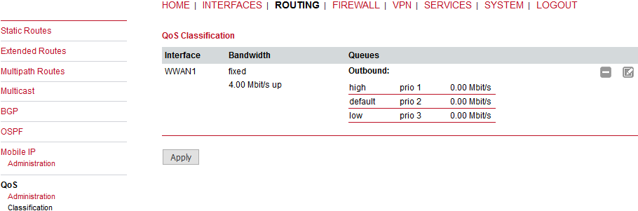
In case an interface has been activated, the system will automatically create the following queues:
high: | A high priority queue which may hold any latency-critical services (such as VoIP). |
default: | A default queue which will handle all other services. |
low: | A low priority queue which may hold less-critical services for which shaping is intended. |
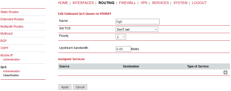
Each queue can be configured as follows:
Name: | The name of the QoS queue. |
Priority: | A numerical priority for the queue, lower values indicate higher priorities. |
Bandwidth: | The maximum possible bandwidth for this queue in case the total bandwidth of all queues exceeds the set upstream bandwidth of “QoS Interface Parameters”. |
Set TOS | The TOS/DiffServ value to set on matching packets. |
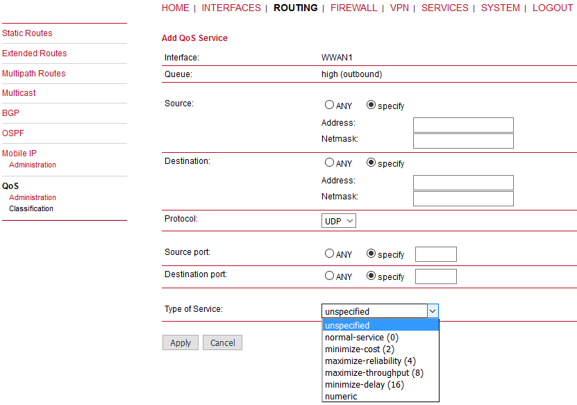
You can now configure and assign any services to each queue. The following parameters apply:
Interface: | The QoS interface of the queue |
Queue: | The QoS queue to which this service shall be assigned |
Source: | Specifies a network address and netmask used to match the source address of packets |
Destination: | Specifies a network address and netmask used to match the destination (target) address of packets |
Protocol: | Specifies the protocol for packets to be matched |
Type of Service: | Specifies the ToS/DiffServ for packets to be matched |
This router uses Linux’s netfilter/iptables firewall framework (see http://www.netfilter.org for more information). It is set up of a range of rules which control each packet’s permission to pass the router. Packets, not matching any of the rules, are allowed by default.
The administration page can be used to enable and disable firewalling. When turning it on, a shortcut can be used to generate a predefined set of rules which allow administration (over HTTP, HTTPS, SSH or TELNET) by default but block any other packets coming from the WAN interface. Please note that the specified rules are processed by order, that means, traversing the list from top to bottom until a matching rule is found. If there is no matching rule found, the packet is allowed.
Administrative status: | Enable or disable packet filtering. |
Allow WAN administration: | This option will predefine the rules for services on the WAN link as follows (TCP ports 80, 443, 22 and 23): |
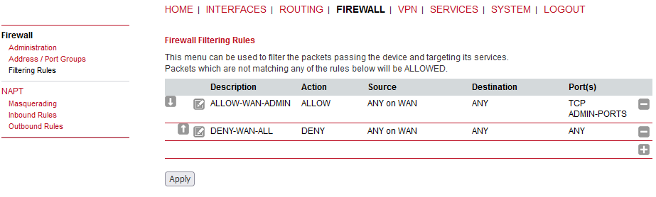
This menu can be used to form address or port groups which can be later used for firewall rules in order to reduce the number of rules.
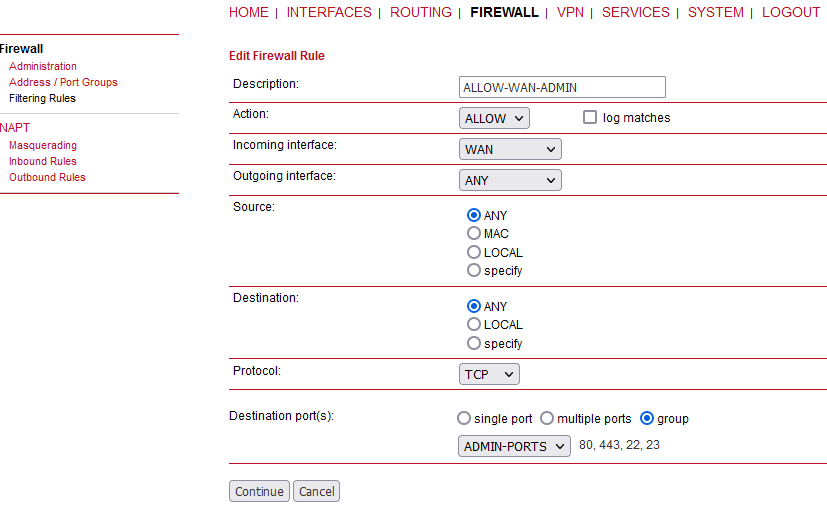
Description: | A meaningful description about the purpose of this rule. |
Action: | Whether the packets of this rule should be allowed or denied. |
Log matches | Throw a syslog message if rule matches. |
Incoming interface: | The Interface on which matching packets are received. |
Outgoing interface: | The interface on which matching packets are received. |
Source: | Source address of matching packets. Possible values are “ANY”, “LOCAL” (addressed to the system itself), “Group” or “Specify” (specified by an address/netmask). |
Destination: | The destination address of matching packets, can be “ANY”, “LOCAL” (addressed … itself), “Group” or “Specify (specified by address/netmask). |
Protocol: | Used IP protocol of matching packets. |
Destination port(s): | Destination port of matching packets. You can specify a single port or a range of ports here. Note that protocol must be set to UDP/TCP when using port filters. |
M!DGE can be configured with its Ethernet interfaces being bridged. In this case, the transparent firewall functionality can be configured to limit reachability of individual hosts connected to M!DGE based on their MAC addresses, i.e. units connected to ETH1 cannot communicate to units connected to ETH2.
| Note | |
|---|---|
Asymmetric routing is when a packet takes one path to the destination and takes another path when returning to the source. These data were dropped by M!DGE2 firewall preceding 4.4.40.104 firmware release. It could cause temporary issues if RipEX Backup paths were configured in the network. It can be controlled now via CLI. The required parameter is “firewall.invalid_ip”.
|
This page allows setting of the options for Network Address and Port Translation (NAPT). NAPT translates IP addresses or TCP/UDP ports and enables communication between hosts on a private network and hosts on a public network. It generally allows a single public IP address to be used by many hosts from the private LAN network.
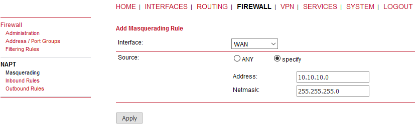
The administration page lets you specify the interfaces on which masquerading will be performed. NAT will hereby use the address of the selected interface and choose a random source port for outgoing connections and thus enables communication between hosts from a private local area network towards hosts on the public network.
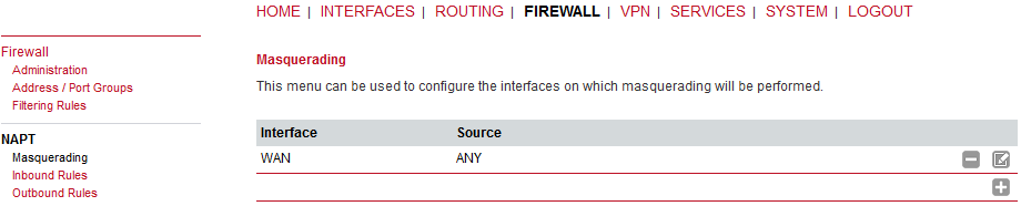
Interface | The outgoing interface on which connections will be masqueraded. |
Source address | The source address or network from which matching packets are masqueraded. |
Inbound rules can be used to modify the target section of IP packets and, for instance, forward a service or port to an internal host. By doing so, you can expose that service and make it available from the Internet. You may also establish 1:1 NAT mapping for a single host using additional outbound rules.
| Note | |
|---|---|
The rules are processed by order, that means, traversing the list from top to bottom until a matching rule is found. If there is no matching rule found, the packet will pass as is. |
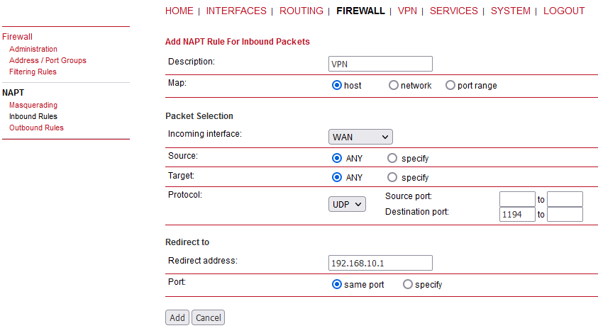
Description: | A meaningful rule description |
Incoming interface: | Interface from which matching packets are received. |
Source | The source address or network from which matching packets are received. |
Map: | Choosing whether the rule applies to the host (one given host), network (subnet to subnet) or port range (IP and port range to subnet and port, e.g., 10.0.0.1:22000-22255 -> 192.168.1.0/24:22). |
Target: | Destination address of matching packets (optional) |
Protocol: | ANY, ESP, GRE protocols or UDP/TCP protocols with an option to define both the source and destination port ranges. |
Redirect to Address: | Address to which matching packets will be redirected. |
Redirect to Port: | Port to which matching packets will be targeted. |
Outbound rules will modify the source section of IP packets and can be used to establish 1:1 NAT mappings but also to redirect packets to a specific service.
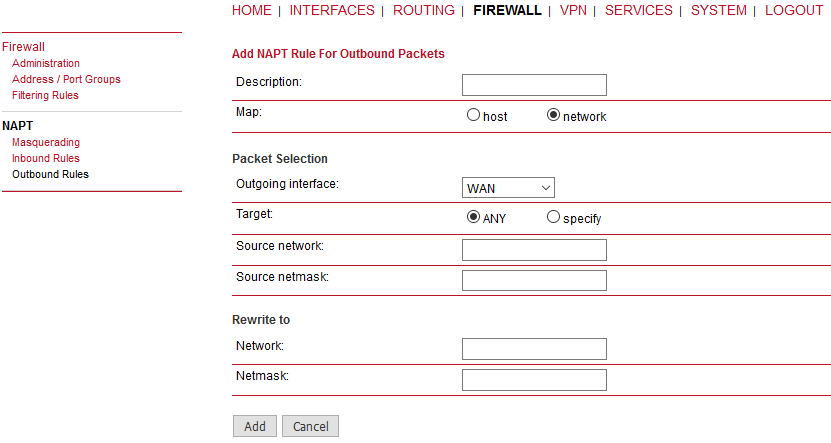
Description: | A meaningful description of this rule |
Map: | Choosing whether the rule applies to the host or to the network. |
Outgoing interface: | Outgoing interface on which matching packets are leaving the router. |
Target | The target address or network to which matching packets are destined. |
Source address: | The source IP address (if Map is set to “host”) |
Protocol | ANY, or UDP/TCP source and destination port ranges (if Map is set to “host”) |
Source network/netmask: | Source network/netmask of matching packets (if Map is set to “network”) |
Rewrite to address/port: | Address/port to which the source address/port of matching packets will be rewritten to |
Rewrite to network/netmask: | Network/netmask to which the source network/netmask of matching packets will be rewritten to |
OpenVPN administrative status | Enable or disable OpenVPN. |
Restart on link change | If checked, the tunnel is restarted whenever any link changes the status. |
Multipath TCP | Enables OpenVPN multipath TCP support. |
If enabled, OpenVPN client configurations will be started whenever a WAN link has been established. Server configuration will be started immediately after the bootup.

The router supports a single server tunnel and up to 4 client tunnels. You can specify tunnel parameters in standard configuration or upload an expert mode file which has been created in advance. Refer to section Section 7.5.1.3, “Client Management” to learn more about how to manage clients and generate the files.
Operation mode | Choose the client or server mode for this tunnel |
| Note | |
|---|---|
M!DGE can be running up to 4 OpenVPN tunnels in the Client mode, but only one tunnel in the Server mode. |
Client Mode
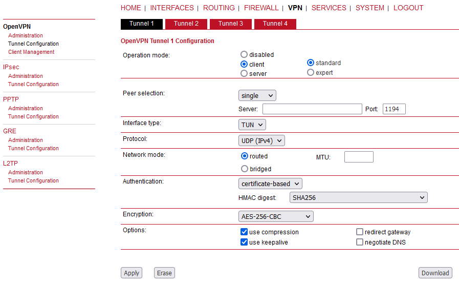
Peer selection | Specifies how the remote peer shall be selected, besides a single server you may configure multiple servers which can , in case of failures, either be selected sequentially (i.e. failover) or randomly (i.e. load balancing).
| ||||
Interface type | The VPN device type which can be either TUN (typically used for routed connections) or TAP (used for bridged networks) | ||||
Protocol | The OpenVPN tunnel protocol to be used. UDP or TCP can be selected and also IPv4 or IPv6. | ||||
Network mode | Defines how the packets should be forwarded, can be routed or bridged from or to a particular interface. You can also set the MTU for the tunnel. | ||||
Authentication | You can choose between credential-based (where you have to specify a username and password) and certificate-based options. Note that keys/certificates have to be created in the SYSTEM -> Keys & Certificates menu. You may also upload files which you have generated on your host system. | ||||
HMAC digest | HMAC is commonly used message authentication algorithm (MAC) that uses a data string, a secure algorithm, and a key, to produce a digital signature. OpenVPN’s HMAC usage is to first encrypt a packet, then HMAC the resulting cipher text. If OpenVPN receives a packet with a bad HMAC, it drops this packet. HMAC usually adds 16 or 20 Bytes per packet. | ||||
Encryption | Required cipher mechanism used for encryption. | ||||
Use compression | Enable or disable OpenVPN compression. | ||||
Use keepalive | Can be used to send a periodic keep alive packet in order to keep the tunnel up despite inactivity. | ||||
Redirect gateway | By redirecting the gateway, all packets will be directed to the VPN tunnel. Please ensure that essential services (such as DNS or NTP servers) can be reached via the network behind the tunnel. If in doubt, create an extra static route pointing to the correct interface. | ||||
Negotiate DNS | If enabled, the system will use the nameservers which have been negotiated over the tunnel. |
Server Mode
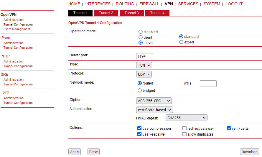
Additional settings (compared to the client mode):
Allow duplicates | Allow multiple clients with the same common name to concurrently connect. |
Verify certs | Check peer certificate against local CRL. |
A server tunnel typically requires the following files:
server.conf (OpenVPN configuration file),
ca.crt (root certificate file),
server.crt (certificate file),
server.key (private key file),
dh.pem (Diffie Hellman parameters file),
a directory (with default name “ccd”) containing client-specific configuration files.
| Important | |
|---|---|
OpenVPN tunnels require a correct system time. Please ensure that all NTP servers are reachable. When using host names, a working DNS server is required as well. |
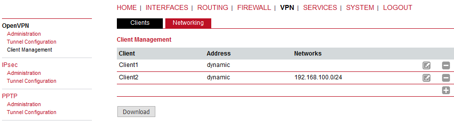
Once you have successfully set up an OpenVPN server tunnel, you can manage and enable clients connecting to your service. Currently connected clients can be seen on this page, including the connect time and IP address. You may kick connected clients by disabling them.
In the Networking section you can specify a fixed tunnel endpoint address for each client. Please note that, if you intend to use a fixed address for a particular client, you would have to apply fixed addresses to the other ones as well.
You may specify the network behind the clients as well as the routes to be pushed to each client. This can be useful for routing purposes, e.g. in case you want to redirect traffic for particular networks towards the server. Routing between the clients is generally not allowed but you can enable it if desired.
Finally, you can generate and download all expert mode files for enabled clients which can be used to easily populate each client.
Operating in server mode with certificates, it is possible to block a specific client by “kicking” (disconnecting) him.
| Note | |
|---|---|
The downloaded expert mode file needs to be unzipped and then individual client expert files can be uploaded to the respective routers. |
| Note | |
|---|---|
See the OpenVPN configuration example in our Application notes. |
IPsec is a protocol suite for securing IP communications by authenticating and encrypting each packet of a communication session and thus establishing a secure virtual private network.
IPsec includes various cryptographic protocols and ciphers for key exchange and data encryption and can be seen as one of the strongest VPN technologies in terms of security.
It uses the following mechanisms:
AH | Authentication Headers (AH) provide connectionless integrity and data origin authentication for IP datagrams and ensure protection against replay attacks. |
ESP | Encapsulating Security Payloads (ESP) provide confidentiality, data-origin authentication, connectionless integrity, an anti-replay service and limited traffic-flow confidentiality. |
SA | Security Associations (SA) provide a secure channel and a bundle of algorithms that provide the parameters necessary to operate the AH and/or ESP operations. The Internet Security Association Key Management Protocol (ISAKMP) provides a framework for authenticated key exchange. |
Negotiating keys for encryption and authentication is generally done by the Internet Key Exchange protocol (IKE) which consists of two phases:
IKE phase 1 | IKE authenticates the peer during this phase for setting up an ISAKMP secure association. This can be carried out by either using main or aggressive mode. The main mode approach utilizes the Diffie-Hellman key exchange and authentication is always encrypted with the negotiated key. The aggressive mode just uses hashes of the pre-shared key and therefore represents a less secure mechanism which should generally be avoided as it is prone to dictionary attacks. |
IKE phase 2 | IKE finally negotiates IPsec SA parameters and keys and sets up matching IPsec SAs in the peers which is required for AH/ESP later on. |
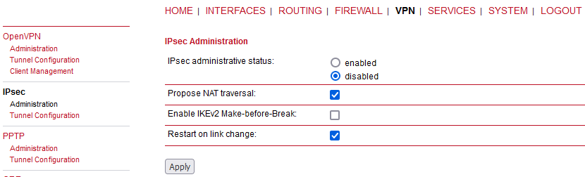
IPsec administrative status | Enable or disable IPsec |
Propose NAT Traversal | NAT-Traversal is mainly used for connections which traverse a path where a router modifies the IP address/port of packets. It encapsulates packets in UDP and therefore requires a slight overhead which has to be taken into account when running over smallsized MTU interfaces. |
Make-before-break | This parameter is valid for all IKE SA using IKEv2 with re-authentication. A temporary connection breaks during IKE_SA re-authentication is suppressed by this parameter. This function may not operate correctly with some IPsec implementations (on peer side). |
Restart on link change | If checked, the tunnel is restarted whenever any link changes the status. |
| Note | |
|---|---|
Running NAT-Traversal makes IKE using UDP port 4500 rather than 500 which has to be taken into account when setting up firewall rules. |
| Note | |
|---|---|
Since the firmware 4.4.40.104, the maximum number of IPsec tunnels has increased from 4 to 10. |
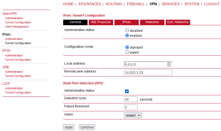
General
Administrative status | Enable or disable particular IPsec tunnel. |
Configuration mode | Use the expert configuration file, or configure all manually. |
Local address | Local address for IPsec data – change it to a particular WAN IP address in case of multiple WANs and dynamic routing configured in a M!DGE2 unit. Otherwise, keep a dynamic default value 0.0.0.0. |
Remote peer address | The IPsec peer/responder/server IP address or host name (if 0.0.0.0 is provided, M!DGE is in IPsec “passive” mode). |
Administrative status | Enable or disable Dead Peer Detection. DPD will detect any broken IPsec connection, in particular the ISAKMP tunnel, and refresh the corresponding SAs (Security Associations) and SPIs (Security Payload Identifiers) for a faster tunnel re-establishment. |
Detection cycle | Set the delay (in seconds) between Dead Peer Detection (RFC 3706) keepalives (R_U_THERE, R_U_THERE_ACK) that are sent for this connection (default 30 seconds). |
Failure threshold | The number of unanswered DPD R_U_THERE requests until the IPsec peer is considered dead (the router will then try to re-establish a dead connection automatically). |
Action | The action when a DPD enabled peer is declared dead. Hold (default) means the eroute is put into the hold status, while clear means the eroute and SA will both be cleared. Restart means that the SA will be immediately renegotiated. |
IKE Proposal
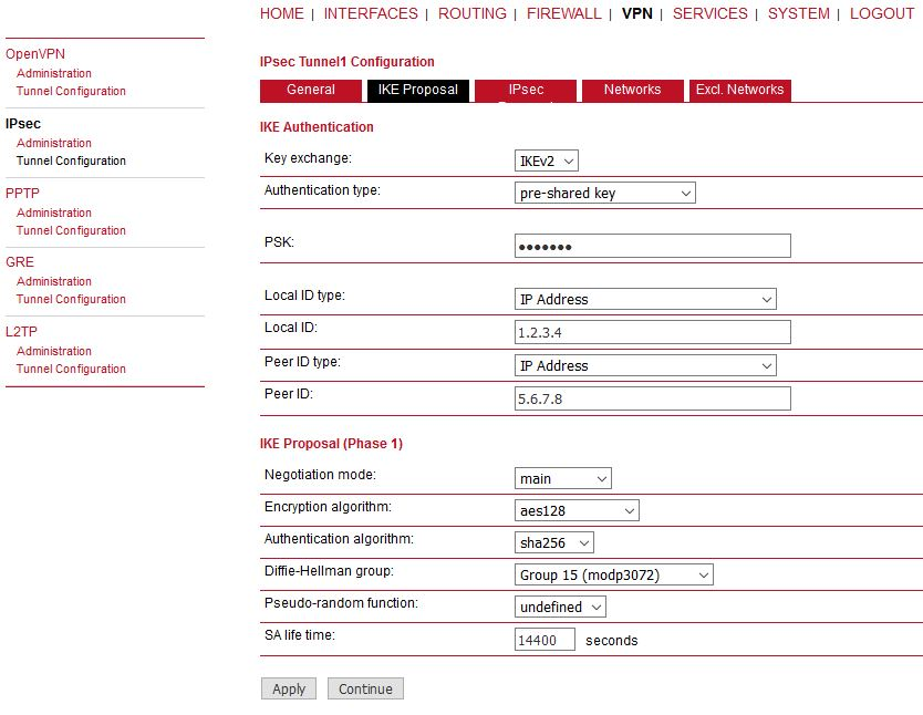
RACOM routers support IKEv1 or IKEv2 authentication via the pre-shared keys (PSK) or certificates within a public key infrastructure.
Using PSK requires the following settings:
PSK | The pre-shared key used |
Local ID Type | The identification type for the local router which can be FQDN, username@FQDN or IP address |
Local ID | The local ID value |
Peer ID type | The identification type for the remote router |
Peer ID | The peer ID value |
Negotiation mode | Choose the negotiation mode (main, aggressive). The aggressive mode has to be used when dealing with dynamic endpoint addresses, but it is referred to be less secure compared to the main mode as it reveals your identity to an eavesdropper. |
Encryption algorithm | The IKE encryption method (default: aes128) |
Authentication algorithm | The IKE authentication method (default: sha256) |
IKE Diffie-Hellman group | The IKE Diffie-Hellman group (default: group15) |
Pseudo-random function | The PRF algorithms that can be used. |
SA life time | The Security Association lifetime (default: 14400 s) |
Using Public Key Infrastructure requires similar settings, but the Operation mode must be configured.
Operation mode
Mode can be set either to “server” or “client”. As a “server” and once you have successfully set up an IPsec tunnel, you can manage and enable clients connecting to your service. It is possible to generate and download expert mode files for enabled clients which can be used to easily populate each client.
When using certificates you would need to specify the Operation mode. When run as the PKI client you can create a Certificate Signing Request (CSR) in the certificates section which needs to be submitted at your Certificate Authority and imported to the router afterwards. In the PKI server mode the router represents the Certificate Authority and issues the certificates for remote peers.
Using XAUTH the following settings can be made:
| Parameter IPsec | XAUTH Settings |
| User name | The name of the XAUTH user |
| User password | The password of the XAUTH user |
| Group name | The group ID |
| Group password | The group secret |
IPsec Proposal
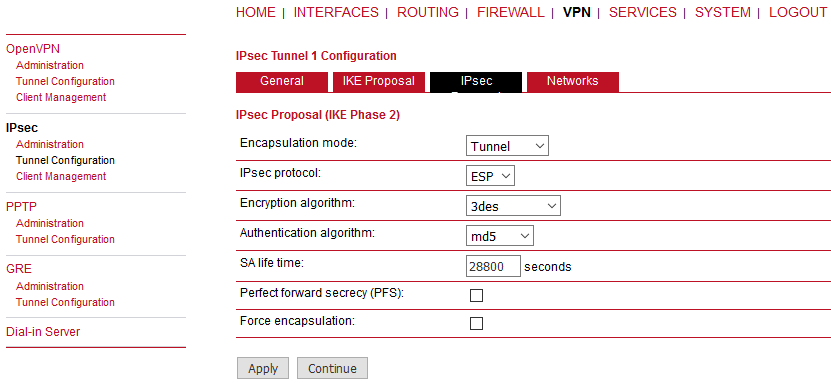
Encapsulation mode | Choose either the Tunnel mode or Transport mode. |
IPsec protocol | Only the ESP IPsec protocol is enabled. |
Encryption algorithm | The IKE encryption method (default: aes128) |
Authentication algorithm | The IKE authentication method (default: sha256) |
SA life time | The Security Association lifetime in seconds (default: 3600 s) |
Perfect forward secrecy (PFS) | Specifies whether Perfect Forward Secrecy (PFS) should be used. This feature increases security as PFS avoids penetration of the key-exchange protocol and prevents compromization of previous keys. |
Force encapsulation | Force UDP encapsulation for ESP packets even if no NAT situation is detected. |
Networks
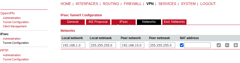
When creating Security Associations, IPsec keeps track of routed networks within the tunnel. Packets are only transmitted when a valid SA with the matching source and destination network is present. Therefore, you may need to specify the networks behind the endpoints by applying the following settings:
Local network address | The address of your Local Area Network (LAN) |
Local network mask | The netmask of your LAN |
Peer network address | The address of the remote network behind the peer |
Peer network mask | The netmask of the remote network behind the peer |
NAT address | Optionally, you can apply NAT (masquerading) for packets coming from a different local network. The NAT address must reside in the network previously specified as the local network. It is now possible to disable Source-NAT rules for single IPsec SA’s. |
| Note | |
|---|---|
Since the firmware 3.7.40.103, the maximum number of networks for individual IPsec tunnels has increased from 4 to 10. |
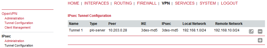
Excl. Networks
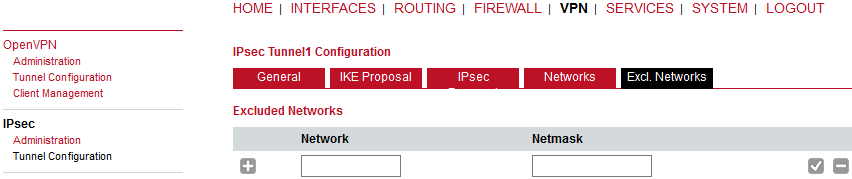
If IPsec is used as default gateway (Remote Network 0.0.0.0/0), this option can be used to exclude some subnet/network. I.e. IPsec is not used for this particular subnet/network.
| Note | |
|---|---|
See the IPsec configuration example in our Application notes. |
The Point-to-Point Tunneling Protocol (PPTP) is a method for implementing virtual private networks between two hosts. PPTP is easy to configure and widely deployed amongst Microsoft Dial-up networking servers. However, due to its weak encryption algorithms, it is nowadays considered insecure but it still provides a straightforward way for establishing tunnels. When setting up a PPTP tunnel, you would need to choose between server or client.
Listen address | Specifies on which IP address should be listened for incoming client connections |
Server address | The server address within the tunnel |
Client address range | Specifies a range of IP addresses assigned to each client |
Username/password | The common username/password configuration |
Once configured, individual clients can be configured with different credentials and IP addresses.
A client tunnel requires the following parameters to be set:
Server address | The address of the remote server |
Username | The username used for authentication |
Password | The password used for authentication |
The Generic Routing Encapsulation (GRE) is a tunneling protocol that can encapsulate a wide variety of network layer protocols inside virtual point-to-point links over IP. GRE is defined in RFC 1701, 1702 and 2784. It does not provide encryption nor authorization but can be used on an address-basis on top of other VPN techniques (such as IPsec) for tunneling purposes.
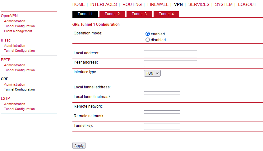
The following parameters are required for setting up a tunnel:
Local address | The IP address which is used as the source IP address of the GRE packets (optional, useful in case of multiple WANs – choose a correct WAN IP). |
Peer address | The remote peer IP address |
Interface type | The device type for this tunnel. If “tap” device is chosen, another parameter “Bridge interface” must be configured with one LAN port. |
Local tunnel address | The local IP address of the tunnel |
Local tunnel netmask | The local subnet mask of the tunnel |
Remote network | The remote network address of the tunnel |
Remote netmask | The remote subnet mask of the tunnel |
Tunnel key | GRE tunnel key allows the remote server to distinguish between GRE packets from different communication partners. |
In general, the local tunnel address/netmask should not conflict with any other interface addresses. The remote network/netmask will result in an additional route entry in order to control which packets should be encapsulated and transferred over the tunnel.
The Layer 2 Tunnelling Protocol is a tunnelling protocol which does not support any encryption or confidentiality. It relies on an encryption protocol that it passes within the tunnel to provide privacy. L2TPv3 is supported. Tunnel can be bridged to the local interfaces.
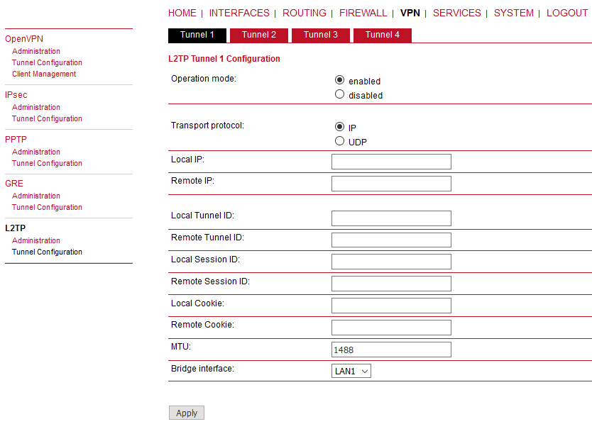
The following parameters are required for setting up a tunnel:
Transport protocol | The transport protocol which shall be used |
Local IP | The local IP address of the tunnel |
Remote IP | The remote IP address of the tunnel |
Local port | The local port address of the tunnel |
Remote port | The remote port address of the tunnel |
Local tunnel ID | The local tunnel ID identifies the tunnel into which the session will be created |
Remote tunnel ID | The remote tunnel ID identifies the tunnel assigned by the peer |
Local session ID | The local session ID identifies the session being created |
Remote session ID | The remote session ID identifies the session assigned by the peer |
Local cookie | The local cookie sets an optional cookie value to be assigned to the session |
Remote cookie | The remote cookie set an optional per cookie value to be assigned to the session |
MTU | The Maximum Transmission Unit of the tunnel interface |
Bridge interface | The interface to which the guest interface shall be bridged |
The Dial-in Server is not supported by M!DGE hardware. Use the “Modem bridge” mode in the Interfaces – Serial menu.
Besides the admin account you can configure further users in the user accounts section, which shall be allowed to dial-in. Please note that Dial-In connections are generally discouraged. As they are implemented as GSM voice calls, they suffer from unreliability and poor bandwidth.
RACOM routers are shipping with a Software Development Kit (SDK) which offers a simple and fast way to implement customer-specific functions and applications. It consists of:
An SDK host which defines the runtime environment (a so-called sandbox), that is, controlling access to system resources (such as memory, storage and CPU) and, by doing so, catering for the right scalability.
An interpreter language called arena, a light-weight scripting language optimized for embedded systems, which uses a syntax similar to ANSI-C but adds support for exceptions, automatic memory management and runtime polymorphism on top of that.
A RACOM-specific Application Programming Interface (API), which ships with a comprehensive set of functions for accessing hardware interfaces (e.g. digital IO ports, GPS, external storage media, serial ports) but also for retrieving system status parameters, sending E-Mail or SMS messages or simply just to configure the router.
Anyone, reasonably experienced in the C language, will find an environment that is easy to
dig in. However, feel free to contact us via <support@racom.eu> and we will
happily support you in finding a programming solution to your specific problem.
The arena scripting language offers a broad range of POSIX functions (like printf or open) and provides, together with tailor-made API functions, a simple platform for implementing any sort of applications to interconnect your favourite device or service with the router.
Here comes a short example:
/* This script prints short status and if the SMS section is setted properly, the status will be send even to your mobile phone :-)
 */

printf("------------------------------");
printf("\n\n");
printf(nb_status_summary(all));
printf("\n\n");
printf("------------------------------");

/* Please change the following number to your mobile phone number
 */
nb_sms_send("+420123456789", nb_status_summary(all));
A set of example scripts can be downloaded directly from the router, you can find a list of them in the appendix. The manual at menu SERVICES-Administration-Troubleshooting-SDK API gives a detailed introduction of the language, including a description of all available functions.
The current range of API functions can be used to implement the following features:
Send/Retrieve SMS
Send E-mail
Read/Write from/to serial device
Control digital input/output ports
Run TCP/UDP servers
Run IP/TCP/UDP clients
Access files of mounted media (e.g. an USB stick)
Retrieve status information from the system
Get or set configuration parameters
Write to syslog
Transfer files over HTTP/FTP
Perform config/software updates
Control the LEDs
Get system events, restart services or reboot system
Scan for networks in range
Create your own web pages
Voice control functions
SNMP functions
Various network-related functions
Other system-related functions
The SDK API manual at menu SERVICES-Administration-Troubleshooting-SDK API provides an overview but also explains all functions in detail.
Please note that some functions require the corresponding services (e.g. E-Mail, SMS) to be properly configured prior to utilizing them in the SDK.
Let’s now pay some attention to the very powerful API function nb_status. It can be used to query the router’s status values in the same manner as they can be shown with the CLI. It returns a structure of variables for a specific section (a list of available sections can be obtained by running cli status -h).
By using the dump function you can figure out the content of the returned structure:
/* Dump current WAN status */

dump ( nb_status ("wan") );
The script will then generate lines like maybe these:
struct(35): {
  .WANLINK1_GATEWAY = string[3]: "n/a"
  .WANLINK2_REGISTRATION_STATE = string[23]: "registeredInHomeNetwork"
  .WANLINK1_STATE = string[7]: "dialing"
  .WANLINK2_STATE_UP_SINCE = string[19]: "2018-12-03 09:08:30"
  .WANLINK1_DIAL_ATTEMPTS = string[3]: "320"
  .WANLINK2_SIGNAL_STRENGTH = string[3]: "-69"
  .WANLINK2_DATA_DOWNLOADED = string[6]: "747608"
  .WANLINK2_DATA_UPLOADED = string[7]: "1225984"
  .WANLINK1_DATA_UPLOADED = string[3]: "n/a"
  .WANLINK2_ADDRESS = string[11]: "10.203.0.28"
  .WANLINK2_NETWORK = string[7]: "O2 - CZ"
  .WANLINK1_DIAL_SUCCESS = string[1]: "0"
  .WANLINK2_PDP = string[4]: "PDP1"
  .WANLINK1_ADDRESS = string[3]: "n/a"
  .WANLINK1_DOWNLOAD_RATE = string[1]: "0"
  .WANLINK2_SIM = string[4]: "SIM1"
  .WANLINK2_DOWNLOAD_RATE = string[2]: "52"
  .WANLINK1_UPLOAD_RATE = string[1]: "0"
  .WANLINK2_SIGNAL_LEVEL = string[2]: "46"
  .WANLINK2_SIGNAL_QUALITY = string[4]: "good"
  .WANLINK2_UPLOAD_RATE = string[2]: "85"
  .WANLINK2_DIAL_FAILURES = string[1]: "0"
  .WANLINK1_TYPE = string[3]: "eth"
  .WANLINK1_DIAL_FAILURES = string[3]: "319"
  .WANLINK2_DIAL_ATTEMPTS = string[1]: "3"
  .WANLINK2_MODEM = string[7]: "Mobile1"
  .WANLINK1_INTERFACE = string[4]: "LAN4"
  .WANLINK1_DATA_DOWNLOADED = string[3]: "n/a"
  .WAN_HOTLINK = string[8]: "WANLINK2"
  .WANLINK2_INTERFACE = string[5]: "WWAN1"
  .WANLINK2_SERVICE_TYPE = string[3]: "LTE"
  .WANLINK2_DIAL_SUCCESS = string[1]: "3"
  .WANLINK2_TYPE = string[4]: "wwan"
  .WANLINK1_STATE_DIALING_SINCE = string[19]: "2018-12-03 12:15:10"
  .WANLINK2_STATE = string[2]: "up"
}
In combination with the nb_config_set function, it is possible to start a re-configuration of any parts of the system upon status changes. You may find all possible parameters by reading the /etc/config/factory-config.cfg file accessible via CLI.
~ $ cat /etc/config/factory-config.cfg | grep ntp
network.ntp.status                              =1
network.ntp.server0                             =0.pool.ntp.org
network.ntp.server1                             =1.pool.ntp.org
network.ntp.ping                                =1
network.ntp.interval                            =256
network.ntp.gpstime                             =0
network.ntp.stratum                             =15
network.ntp.access.0.address                    =192.168.1.0
network.ntp.access.0.netmask                    =255.255.255.0
network.ntp.access.1.address                    =
network.ntp.access.1.netmask                    =
network.ntp.access.2.address                    =
network.ntp.access.2.netmask                    =
Here is an example how one might adopt those functions:
/* Check the current NTP server and set it to the IP address 192.168.0.2
and enable the NTP synchronisation */

printf ("The NTP server was previously using IP address: ");
printf (nb_config_get("network.ntp.server0"));
printf("\n\n");

nb_config_set("network.ntp.server0=192.168.0.2");

if (nb_config_get ("network.ntp.status") == "0"){
  printf ("and was not running.");
  printf("\n\n");
  nb_config_set ("network.ntp.status=1");
}
else {
  printf ("and was running.");
  printf("\n\n");
}

printf ("The NTP server is now running with IP address: ");
printf (nb_config_get("network.ntp.server0"));In the SDK, we are speaking of scripts and triggers which form
jobs. Any arena script can be uploaded to the router or imported
by using dedicated user configuration packages. You may also edit the script directly at the
Web Manager or select one of our examples. You also have a testing section on the router
which can be used to check your syntax or doing test runs.
Once uploaded, you will have to specify a trigger, that is, telling the router when the script is to be executed. This can be either time-based (e.g. each Monday) or triggered by one of the pre-defined system events (e.g. wan-up) as described in Section 7.6.7, “Events”. With both, a script and a trigger, you can finally set up an SDK job now. The test event usually serves as a good facility to check whether your job is working as expected. The admin section also offers facilities to troubleshoot any issues and control running jobs. The SDK host (sdkhost) corresponds to the daemon managing the scripts and their operations and thus avoiding any harm to the system. In terms of resources, it will limit CPU and memory for running scripts and also provide a pre-defined portion of the available flash storage. You may, however, extend it by external USB storage.
Files written to/tmp will be hold in the memory and will be cleared upon a
script restart.. As your scripts operate in the sandbox, you will have no access to the
system tools (such as ifconfig).
Administration
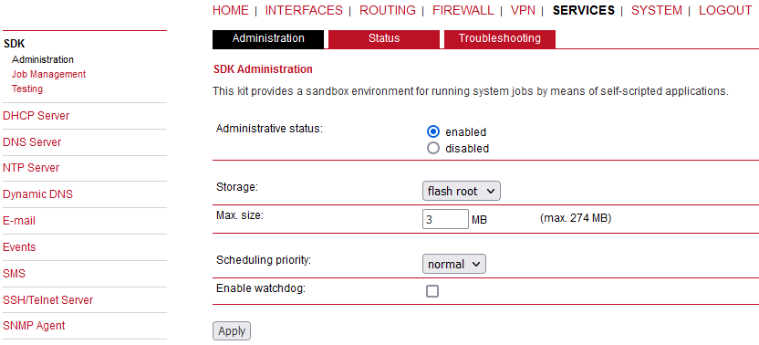
This page can be used to control the SDK host and apply the following settings:
Administrative status | Specifies whether SDK scripts should run or not |
Scheduling priority | Specifies the process priority of the sdkhost, higher priorities will speed up scheduling your scripts, lower ones will have less impact to the host system |
Maximum flash usage | The maximum amount of Mbytes your scripts can write to the flash root or flash data |
Enable watchdog | This option enables watchdog supervision for each script. If the script does not respond or is stopped with an exit code not equal null, the system is rebooted. |
The status page informs you about the current SDK status. It provides an overview about any finished jobs, you can also stop a running job there and view the script output in the troubleshooting section where you will also find links for downloading the manuals and examples.
Job Management
This page can be used to set up scripts, triggers and jobs.
It is usually a good idea to create a trigger first which is made up by the following parameters:
Name | A meaningful name to identify the trigger |
Type | The type of the trigger, either time-based or event-based |
Condition | Specifies the time condition for time-based triggers (e.g. hourly) |
Timespec | The time specification which, together with the condition, specifies the
|
Event | The system event upon which the trigger should be pulled |
You can now add your personal script to the system by applying the following parameters:
Name | A meaningful name to identify the script |
Description | An optional script description |
Arguments | An optional set of arguments passed to the script (supports quoting) |
Action | You may either edit a script, upload it to the system or select one of the example scripts or an already uploaded script  |
You are ready to set up a job afterwards, it can be created by using the following parameters:
Name | A meaningful name to identify the job |
Trigger | Specifies the trigger that should launch the job |
Script | Specifies the script to be executed |
Arguments | Defines arguments which can be passed to the script (supports quoting), they will precede the arguments you formerly may have assigned to the script itself |
Testing
/* Check the current NTP server and set it to the IP address 192.168.0.2
and enable the NTP synchronisation */

printf ("The NTP server was previously using IP address: ");
printf (nb_config_get("network.ntp.server0"));
printf("\n\n");

nb_config_set("network.ntp.server0=192.168.0.2");

if (nb_config_get ("network.ntp.status") == "0"){
  printf ("and was not running.");
  printf("\n\n");
  nb_config_set ("network.ntp.status=1");
}
else {
  printf ("and was running.");
  printf("\n\n");
}

printf ("The NTP server is now running with IP address: ");
printf (nb_config_get("network.ntp.server0"));
The testing page offers an editor and an input field for optional arguments which can be used to perform test runs of your script or test dedicated portions of it. Please note that you might need to quote arguments as they will otherwise be separated by white-spaces.
/* arguments : schnick schnack "s c h n u c k" */

for (i = 0; i < argc ; i++) {
    printf (" argv %d: %s\n", i, argv [i]);
}

/* generates:
* argv 0: /scripts/testrun
* argv 1: schnick
* argv 2: schnack
* argv 3: s c h n u c k
*/
In case of syntax errors, arena will usually print error messages as follows (indicating the line and position where the parsing error occurred):
/scripts/testrun:2:10:FATAL: parse error, unexpected $, expecting ’;’
| Note | |
|---|---|
It is now possible to upload SDK scripts into the Testing menu via browsing the required SDK script and clicking on the “Run” button. |
As an introduction, you can step through a sample application, namely the SMS control script, which implements remote control over short messages and can be used to send a system status back to the sender. The source code is listed in the appendix.
Once enabled, you can send a message to the phone number associated with a SIM / modem. It generally requires a password to be given on the first line and a command on the second, such as:
admin01
status
We strongly recommend to use authentication in order to avoid any unintended access, however you may pass noauth as argument to disable it. You can then skip the first line containing the password. Having a closer look to the script, you will see that you will also be able to restrict the list of permitted senders. Please inspect the system log for troubleshooting any issues.
The following commands are supported:
status | An SMS with the following information will be returned
|
connect | This will initiate a Dial-out connection over configured WAN (LAN or cellular) and the VPN connection (if enabled) and trigger sending an SMS with the following information:
|
disconnect | terminates all WAN connections (including VPN) |
reboot | Initiates a system reboot |
output 1 on | Switch digital output 1 on |
output 1 off | Switch digital output 1 off |
output 2 on | Switch digital output 2 on |
output 2 off | Switch digital output 2 off |
A response to the status command typically looks like:
System: MIDGE midge (0002A9FFC32E)
WAN1: WWAN1 is up (10.204.8.3, Mobile1,
HSPA, -65 dBm, LAI 23003)
DIO: IN1=off, IN2=off, OUT1=off, OUT2=on
| Note | |
|---|---|
Correct time is a must! Otherwise, old SMS will be dropped. The script is included by default, but it is not working by default (FWs 4.4.40.102 and older). For a proper functionality, you would need to uncheck and then check the “store password” in User management for “admin” user. |
This section can be used to individually configure a DHCP service for each LAN interface.
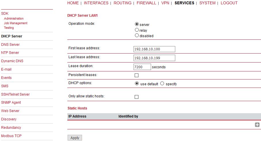
Operational mode | The DHCP operational mode can be disabled or set to the “server” or “relay” mode. As a server, the unit answers to DHCP requests from hosts in the LAN directly. As a relay, the unit resends the requests to the configured DHCP server which handles them. |
First lease address | First address for DHCP clients |
Last lease address | Last address for DHCP clients |
Lease duration | Number of seconds (30-86400) how long a given lease will be valid until it has to be requested again |
Persistent leases | By checking this option, only static hosts will obtain the IP leases |
DHCP options | By default DHCP will hand out the interface address as the default gateway and DNS server address if not configured elsewhere. It is possible to specify different addresses here. |
Static Hosts | The option to add a static host configured with the IP address and identified by MAC address, hostname or Ethernet port. |
The DNS server can be used to proxy DNS requests towards servers on the net which have for instance been negotiated during WAN link negotiation. By pointing DNS requests to the router, one can reduce outbound DNS traffic as it is caching already resolved names but it can be also used for serving fixed addresses for particular host names.
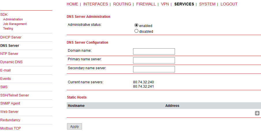
Administrative status | Enabled or disabled |
Domain name | The domain name used for short name lookups. |
Primary name server | The primary default name server which will be used instead of negotiated name servers. |
Secondary name server | The secondary default name server which will be used instead of negotiated name servers. |
You may further configure static hosts for serving fixed IP addresses for various hostnames. Please remember to point local hosts to the router’s address for resolving them.
This section can be used to individually configure the Network Time Protocol (NTP) server function.
Administrative status | Enabled or disabled |
Poll interval | Defines the polling interval (64-4096 seconds) for synchronizing the time with the master clock servers |
Allowed hosts | Defines the IP address range which is allowed to poll the NTP server |
| Note | |
|---|---|
See the description of how to set the correct router time in Section 7.7.1.6, “Time & Region”. |
Dynamic DNS client on this box is generally compatible with various DynDNS services on the Internet running by means of definitions by the DynDNS organization (see www.dyndns.com for server implementations).
Administrative status: | Enabled or disabled |
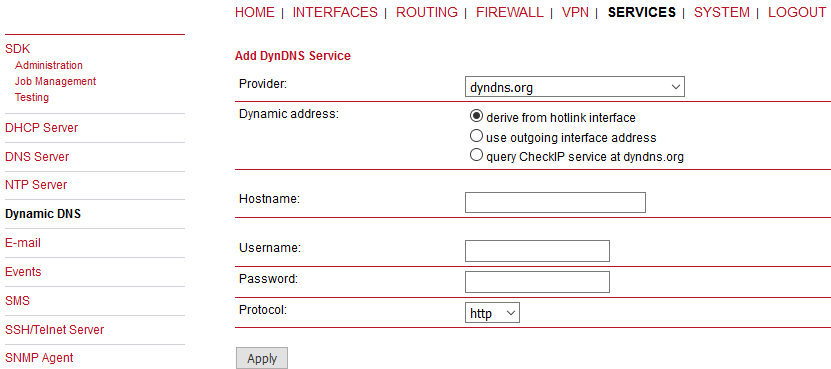
Dynamic address | Specifies whether the address is derived from the hotlink, outgoing interface address or via an external service. Usually, the hotlink option is used. |
Hostname | The host-name provided by your DynDNS service (e.g. mybox.dyndns.org) |
Username | The user-name used for authenticating at the service |
Password | The password used for authentication |
Protocol | The protocol used for authentication (HTTP, HTTPS). |
Server address | The address of the server which shall be updated. |
Server port | The port of the server which shall be updated. |
TSIG key name | The name of the TSIG key which is allowed to perform updates. |
TSIG key | The TSIG key encoded in base64. |
The E-Mail client can be used to send notifications to a particular E-Mail address upon certain events or by SDK scripts.
Administrative status | E-mail client administrative status – enabled or disabled |
From address | Sender e-mail address |
Server address | SMTP server address |
Server port | SMTP server port (typically 25) |
Authentication | Choose the required authentication method to authenticate against the SMTP server |
Encryption | The optional encryption for the e-mail messaging (none or TLS) |
Username | User name for authentication |
Password | Password for authentication |
After configuring E-mail successfully, you can also test e-mail messages.
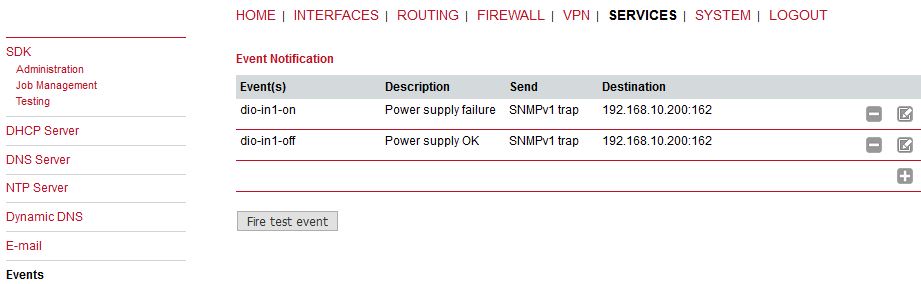
By using the event manager you can notify remote systems about system events. A notification can be sent using E-Mail, SMS or SNMPv1 traps, SNMPv3 traps or SNMPv3 informs.
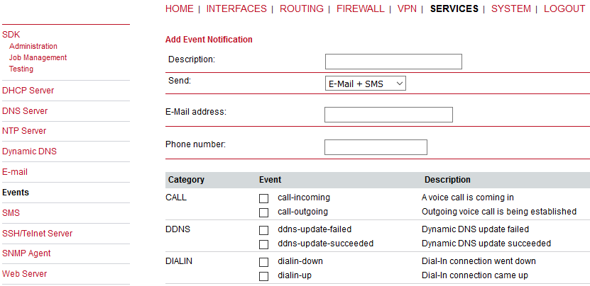
E-Mail address | The E-Mail address to which the notification shall be sent (E-Mail client must be enabled) |
Phone number | The phone number to which the notification shall be sent (SMS service must be enabled) |
SNMP host | The SNMP host or address to which the trap shall be sent |
SNMP port | The port of the remote SNMP service |
Username | The username for accessing the remote SNMP service |
Password | The password for accessing the remote SNMP service |
Authentication | The authentication algorithm for accessing the remote SNMP service (MD5 or SHA) |
Encryption | The encryption algorithm for accessing the remote SNMP service (DES or SHA) |
Engine ID | The engine ID of the remote SNMP service |
The messages will contain a description provided by you and a short system information.
The default texts for a specific Event are as follows:
| Category | Event (ID) | Description |
|---|---|---|
| CALL | call-incoming (701) | A GSM call is coming in |
| call-outgoing (702) | Outgoing voice call is being established | |
| DDNS | ddns-update-failed (802) | Dynamic DNS update failed |
| ddns-update-succeeded (801) | Dynamic DNS update succeeded | |
| DIALIN | dialin-down (409) | Dial-In connection went down |
| dialin-up (408) | Dial-In connection came up | |
| DIO | dio-in1-off (202) | DIO IN1 turned off |
| dio-in1-on (201) | DIO IN1 turned on | |
| dio-in2-off (204) | DIO IN2 turned off | |
| dio-in2-on (203) | DIO IN2 turned on | |
| dio-out1-off (206) | DIO OUT1 turned off | |
| dio-out1-on (205) | DIO OUT1 turned on | |
| dio-out2-off (208) | DIO OUT2 turned off | |
| dio-out2-on (207) | DIO OUT2 turned on | |
| GPS | gps-down (302) | GPS signal is not available |
| gps-up (301) | GPS signal is available | |
| GRE | gre-down (413) | GRE connection went down |
| gre-up (412) | GRE connection came up | |
| IPSEC | ipsec-down (404) | IPsec connection went down |
| ipsec-up (403) | IPsec connection came up | |
| L2TP | l2tp-down (415) | L2TP connection went down |
| l2tp-up (414) | L2TP connection came up | |
| MOBILEIP | mobileip-down (411) | Mobile IP connection went down |
| mobileip-up (410) | Mobile IP connection came up | |
| OPENVPN | openvpn-down (402) | OpenVPN connection went down |
| openvpn-up (401) | OpenVPN connection came up | |
| PPTP | pptp-down (407) | PPTP connection went down |
| pptp-up (406) | PPTP connection came up | |
| REDUNDANCY | redundancy-backup (1002) | System is now backup router |
| redundancy-master (1001) | System is now master router | |
| SDK | sdk-startup (507) | SDK has been started |
| SMS | sms-notsent (602) | SMS has not been sent |
| sms-received (603) | SMS has been received | |
| sms-report-received (604) | SMS report has been received | |
| sms-sent (601) | SMS has been sent | |
| SYSTEM | system-error (510) | System is in error state |
| system-login-failed (501) | User login failed | |
| system-login-succeeded (502) | User login succeeded | |
| system-logout (503) | User logged out | |
| system-no-error (511) | System left error state | |
| system-poweroff (509) | System poweroff has been triggered | |
| system-rebooting (504) | System reboot has been triggered | |
| system-startup (505) | System has been started | |
| system-time-updated (508) | System time has been updated | |
| TEST | test (506) | test event |
| USB | usb-eth-added (903) | USB Ethernet device has been added |
| usb-eth-removed (904) | USB Ethernet device has been removed | |
| usb-serial-added (905) | USB serial device has been added | |
| usb-serial-removed (906) | USB serial device has been removed | |
| usb-storage-added (901) | USB storage device has been added | |
| usb-storage-removed (902) | USB storage device has been removed | |
| WAN | wan-down (101) | WAN link went down |
| wan-up (102) | WAN link came up |
This page lets you turn on the SMS event notification service and enable remote control via SMS.
On RACOM routers it is possible to receive or send short messages (SMS) over each mounted modem (depending on the assembly options). Messages are received by querying the SIM card over a modem, so prior to that, the required assignment of a SIM card to a modem needs to be specified on the SIMs page.
Please bear in mind, in case you are running multiple WWAN interfaces sharing the same SIM, that the system may switch SIMs during operation which will also result in different settings for SMS communication.
Sending messages heavily depends on the registration state of the modem and whether the provided SMS Center service works and may fail. You may use the sms-report-received event to figure out whether a message has been successfully sent.
Received messages are pulled from the SIMs and temporarily stored on the router but get cleared after a system reboot. Please consider to consult an SDK script in case you want to process or copy them.
Sending messages heavily depends on the registration state of the modem and whether the provided SMS Center service works and may fail. You may use the sms-report-received event to figure out whether a message has been successfully sent.
Please do not forget that modems might register roaming to foreign networks where other fees may apply. You can manually assign a fixed network (by LAI) in the SIMs section.
We identify SIMs based on their IMEI number and track their statistics in a non-volatile manner.
The relevant page can be used to enable the SMS service and specify on which modem should operate.
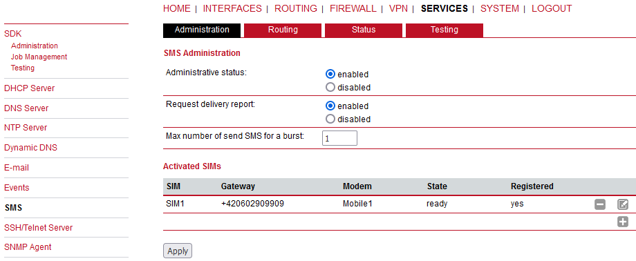
Administrative status | Enable or disable SMS notifications and control |
Request delivery report | Enable or disable receiving the confirmation whether SMS was successfully received or not. This can be then read in the SMS Status menu. |
Max number of send SMS for a burst | Maximum rate of sending SMS events. |
By using SMS routing you can specify outbound rules which will be applied whenever messages are sent. You can forward them to an enabled modem. For a particular number, you can for instance enforce messages be sent over a dedicated SIM.
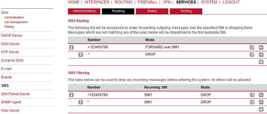
Phone numbers can also be specified by regular expressions, here are some examples:
+12345678   Specifies a fixed number
+1*         Specifies any numbers starting with +1
+1*9        Specifies any numbers starting with +1 and ending with 9
+[12]*      Specifies any numbers starting with either +1 or 2
Please note that numbers have to be entered in international format including a valid prefix. On the other hand, you can also define rules to drop outgoing messages, for instance, when you want to avoid using any expensive service or international numbers.
Both types of rules form a list will be processed in order, forwarding outgoing messages over the specified modem or dropping them. Messages which are not matching any of the rules below will be dispatched to the first available modem.
Filtering serves a concept of firewalling incoming messages, thus either dropping or allowing them on a per-modem basis. The created rules are processed in order and in case of matches will either drop or forward the incoming message before entering the system. All non-matching messages will be allowed.
The status page can be used to the current modem status and get information about any sent or received messages. There is a small SMS inbox reader which can be used to view or delete the messages. Please note that the inbox will be cleared each midnight in case it exceeds 512 kbytes of flash usage.
Apart from the Web Manager, the SSH and Telnet services can be used to log into the system. Valid users include root and admin as well as additional users as they can be created in the User Accounts section. Please note, that a regular system shell will only be provided for the root user, the CLI will be launched for any other user whereas normal users will only be able to view status values, the admin user will obtain privileges to modify the system.
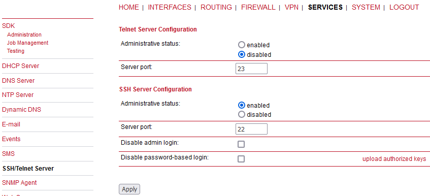
Please note that these services will be accessible from the WAN interface also. In doubt, please consider to disable or restrict access to them by applying applicable firewall rules.
The following parameters can be applied to the Telnet service (disabled by default):
Administrative status | Whether the Telnet service is enabled or disabled |
Server port | The TCP port of the service (usually 23) |
The following parameters can be applied to the SSH service:
Administrative status | Whether the SSH service is enabled or disabled |
Server port | The TCP port of the service (usually 22) |
Disable admin login | If checked, access via SSH for admin and root users will be blocked. Other users may have access as usual, but with restricted privileges. |
Disable password-based login | By turning on this option, all users will have to authenticate by SSH keys which can be uploaded to the router. |
| Note | |
|---|---|
You can manually upload the authorized keys. |
M!DGE is equipped with an SNMP daemon, supporting basic MIB tables (such as ifTable), plus additional enterprise MIBs to manage multiple systems. M!DGE OID starts with 1.3.6.1.4.1.33555.10 prefix. The corresponding VENDOR MIB can be downloaded from the router.
| Parameter | Supported MIBs |
|---|---|
| .1.3.6.1.2.1 | MIB-II (RFC1213), SNMPv2-MIB (RFC3418) |
| .1.3.6.1.2.1.2.1 | IF-MIB (RFC2863) |
| .1.3.6.1.2.1.4 | IP-MIB (RFC1213) |
| .1.3.6.1.2.1.10.131 | TUNNEL-MIB (RFC4087) |
| .1.3.6.1.2.25 | HOST-RESOURCES-MIB (RFC2790) |
| .1.3.6.1.6.3.10 | SNMP-FRAMEWORK-MIB |
| .1.3.6.1.6.3.11 | SNMPv2-SMI (RFC2578) |
| .1.0.8802.1.1.2 | LLDP-MIB |
| .1.0.8802.1.1.2.1.5.4795 | LLDP-EXT-MED-MIB |
| .1.3.6.1.4.1.33555 | VENDOR-MIB (RACOM) |
The VENDOR-MIB tables offer some additional information over the system and its WWAN, GNSS and WLAN interfaces. They can be accessed over the following OIDs:
| Parameter | RACOM MIB OID Assignment |
|---|---|
| admin | .1.3.6.1.4.1.33555.10.40 |
| mgWwanTable | .1.3.6.1.4.1.33555.10.50 |
| mgGnssTable | .1.3.6.1.4.1.33555.10.51 |
| dio | .1.3.6.1.4.1.33555.10.53 |
| mgSerialTable | .1.3.6.1.4.1.33555.10.54 |
| mgWlanTable | .1.3.6.1.4.1.33555.10.60 |
| mgWlanStationTable | .1.3.6.1.4.1.33555.10.61 |
| mgHotLink | .1.3.6.1.4.1.33555.10.70 |
| mgWanTable | .1.3.6.1.4.1.33555.10.71 |
| sdk | .1.3.6.1.4.1.33555.10.90 |
| traps | .1.3.6.1.4.1.33555.10.100 |
| Note | |
|---|---|
GNSS and WLAN on M!DGE are available with special extension only. |
M!DGE extensions contain support for:
Rebooting the device
Updating to a new system software via FTP/TFTP/HTTP
Updating to a new system configuration via FTP/TFTP/HTTP
Getting WWAN/GNSS/WLAN/DIO information
| Note | |
|---|---|
Attention must be paid to the fact that SNMP passwords have to be more than 8 characters long. Shorter passwords will be doubled for SNMP, e.g. ‘admin01’ becomes ‘admin01admin01’. |
SNMP extensions can be read and triggered as follows:
To get system software version:
snmpget -v 3 -u admin -n “” -l authNoPriv -a MD5 -x DES -A admin01admin01 192.168.1.1 1.3.6.1.4.1.33555.10.40.1.0To get a kernel version:
snmpget -v 3 -u admin -n “” -l authNoPriv -a MD5 -x DES -A admin01admin01 192.168.1.1 1.3.6.1.4.1.33555.10.40.2.0To get a serial number:
snmpget -v 3 -u admin -n “” -l authNoPriv -a MD5 -x DES -A admin01admin01 192.168.1.1 1.3.6.1.4.1.33555.10.40.3.0To restart the device:
snmpset -v 3 -u admin -n “” -l authNoPriv -a MD5 -x DES -A admin01admin01 192.168.1.1 1.3.6.1.4.1.33555.10.40.10.0 i 1To run a configuration update:
snmpset -v 3 -u admin -n “” -l authNoPriv -a MD5 -x DES -A admin01admin01 192.168.1.1 1.3.6.1.4.1.33555.10.40.11.0 s “http://server/directory”
| Note | |
|---|---|
config Update expects a zip-file named <serial-number>.zip in the specified
directory which contains at least a “user-config.zip”. |
get configuration update status:
snmpget -v 3 -u admin -n “” -l authNoPriv -a MD5 -x DES -A admin01admin01 192.168.1.1 1.3.6.1.4.1.33555.10.40.12.0
The return value can be one of: (1) succeeded, (2) failed, (3) inprogress, (4) notstarted.run software update:
snmpset -v 3 -u admin -n “” -l authNoPriv -a MD5 -x DES -A admin01admin01 192.168.1.1 1.3.6.1.4.1.33555.10.40.13.0 s “http://server/directory”get software update status:
snmpget -v 3 -u admin -n “” -l authNoPriv -a MD5 -x DES -A admin01admin01 192.168.1.1 1.3.6.1.4.1.33555.10.40.14.0
Return value can be either of: (1) succeeded, (2) failed, (3) inprogress, (4) notstarted.
Administrative status | Enable or disable the SNMP agent |
Operation mode | Specifies if agent should run in compatibility mode or for SNMPv3 only |
Contact | System maintainer or other contact information |
Location | Device location |
Listening port | SNMP agent port |
Once the SNMP agent is enabled, SNMP traps can be generated using SDK scripts or can be triggered by various Events (see the SYSTEM → Events menu).
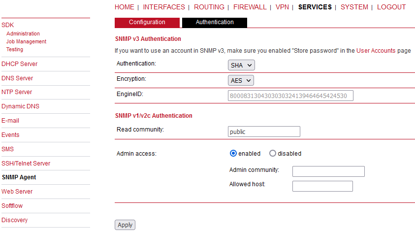
When running in SNMPv3, it is possible to configure the following two authentication options:
Authentication | Defines the authentication (MD5 or SHA) |
Encryption | Defines the privacy protocols to use (DES or AES) |
EngineID | Current EngineID for SNMP secure communication |
Both the Authentication and Encryption passwords are the same and equal to the user’s
password.
In general, the admin user can read and write any values. Read
access will be granted to any other system users. The password must be at least 8
characters long and contain both digits and letters.
There is no authentication/encryption in SNMPv1/v2c and should not be used to set any values. However, it is possible to define its communities and authoritative host which will be granted administrative access.
Read community | Defines the community name for read access via SNMPv2c. The RACOM Enterprise OIDs cannot be read via this Read access – allow the SNMPv3 or use the “Admin” community for RACOM OIDs. |
Admin community | Defines the community name for admin access. Use this community string to read RACOM Enterprise OIDs. |
Allowed host | Defines the host which is allowed for admin access |
| Note | |
|---|---|
The SNMP daemon is also listening on WAN interfaces and it is therefore suggested to restrict the access via the firewall. |
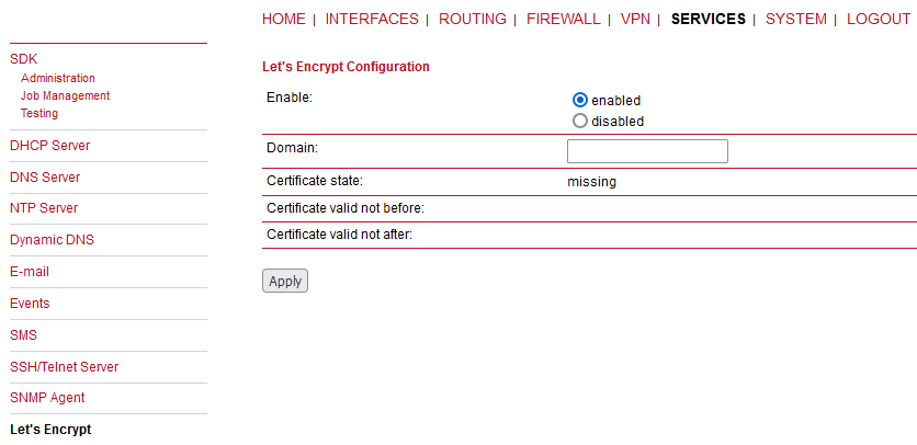
This service allows you to automatically issue TLS certificates for the web interface of the router using the PKI provided by Let’s Encrypt. If HTTPS is enabled, the web interface will automatically use the Let’s Encrypt certificate. Make sure that the following preconditions are met in order to be able to issue and use Let’s Encrypt certificates:
HTTP and HTTPS must be enabled on the web server on the standard ports 80 and 443.
The router must be reachable from the internet using the domain name configured for Let’s Encrypt via TCP ports 80 and 443.
As soon as the Let’s Encrypt component is enabled, it automatically starts requesting a certificate for the configured domain. It also checks once a day if the certificate needs to be renewed and requests a new certificate if necessary.
Enable | Enables/disables the component |
Domain | Domain for which to request a certificate |
Certificate state | Indicates if the certificate is installed or missing or if it is currently being issued |
Certificate valid not before | Time at which the validity of the installed certificate started |
Certificate valid not after | Time at which the validity of the installed certificate ends |
Renew Certificate | Allows to manually request renewal of the certificate. Note that this only works if renewal is due. |
Delete Certificate | Deletes the installed certificate. This is only available if Let’s Encrypt is disabled. |
For debugging, you can use the tail-scripts command in the CLI which shows the log of the
ACME client which requests the certificates. Or you can also find the log of the last
certificate request in the following file:
/etc/acme/<DOMAIN>/issue.log
This page can be used to configure different ports for accessing the Web Manager via HTTP/HTTPS. We strongly recommend to use HTTPS when accessing the web service via a WAN interface as the communication will be encrypted and thus avoids any misuse of the system.
In order to enable HTTPS you would need to generate or upload a server certificate in the section SYSTEM-Keys and Certificates.
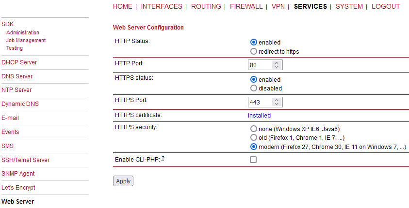
Administrative status | Enable or disable the Web server |
HTTP port | Web server port for HTTP connections |
HTTPS port | Web server port for HTTPS connections |
HTTPS certificate | Either information that the certificate is ‘installed’ or a link to create such certificate. |
HTTPS security | Choose the HTTPS security level – follow the help within the menu itself. |
Enable CLI-PHP | Enable CLI-PHP service (see Section 8.16, “CLI–PHP”) |
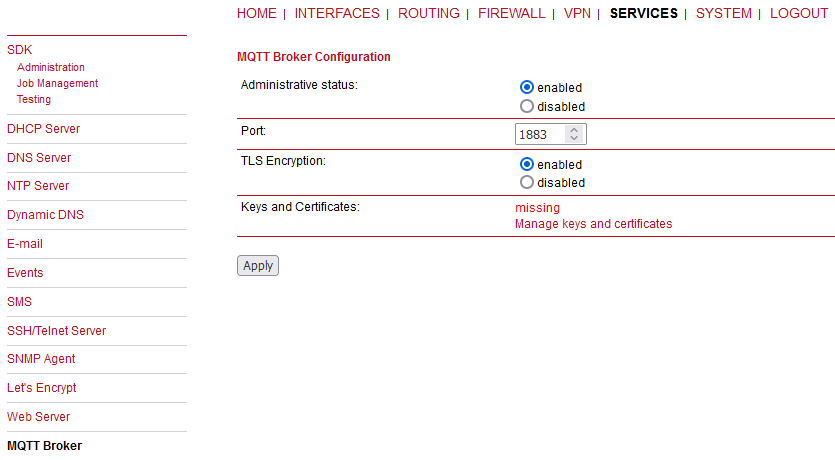
The MQTT Broker can be used to distribute MQTT messages between MQTT clients. Please set up appropriate firewall rules if you want to restrict access to the MQTT Broker.
Keys and certificates for TLS encryption are managed via Keys & Certificates. The MQTT Broker service can receive the following parameters:
Administrative Status | Enable or disable Service |
Port | Specifies the network port to listen on |
TLS Encryption | Enables or disables TLS encryption for the service |
This page can be used to configure the network traffic analyser daemon Softflow used for exporting NetFlow traffic data.
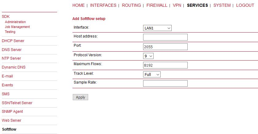
Parameters | Softflow Settings |
Interface | Interface on which to listen for traffic |
Host address | Destination address of the traffic data |
Port | Port of the destination address |
Protocol version | Protocol version of the data |
Maximum flows | The maximum number of flows to concurrently track |
Track level | Flow elements that should be used to define a flow |
Sample rate | Periodical sampling rate |
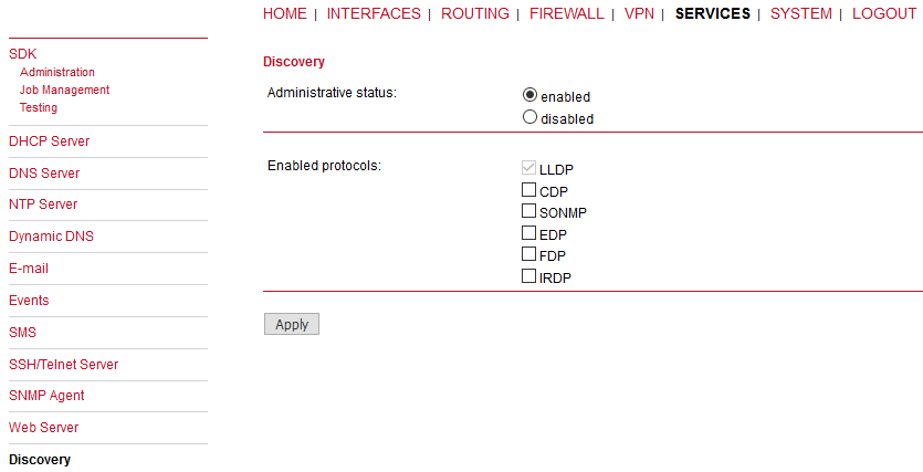
Discovery protocols can be used to discover and to get discovered by other hosts.
Administrative status | Enable or disable the Discovery |
The following protocols are supported:
| LLDP | Link Layer Discovery Protocol |
| CDP | Cisco Discovery Protocol |
| FDP | Foundry Discovery Protocol |
| SONMP | Nortel Discovery Protocol |
| EDP | Extreme Discovery Protocol |
| IRDP | ICMP Router Discovery Protocol |
IRDP implements RFC1256 and can also inform locally connected hosts about the nexthop gateway. Any discovered hosts will be exposed to the LLDP-MIB and can be queried over SNMP or CLI/GUI.
This section can be used to set up a redundant pair of M!DGE (or other systems) by running the Virtual Router Redundancy Protocol (VRRP) among them. A typical VRRP scenario defines the first host playing the master and another the backup device, they both define a virtual gateway IP address which will be distributed by gratuitous ARP messages for updating the ARP cache of all LAN hosts and thus redirecting the packets accordingly.
A takeover will happen within approximately 3 seconds as soon as the partner is no longer reachable (checked via multicast packets). This may happen when one device is rebooting or the Ethernet link went down. Same applies when the WAN link goes down.
In case DHCP has been activated, please keep in mind that you will need to reconfigure the DHCP gateway address offered by the server and let them point to the virtual gateway address. In order to avoid conflicts you may turn off DHCP on the backup device or even better, split the DHCP lease range in order to prevent any lease duplication.
| Note | |
|---|---|
M!DGE assigns a priority of 100 to the master and 1 to the backup router. Please adapt the priority of your third-party device appropriately. |
Administrative status | Enable or disable Redundancy |
Role | Role of this system (either master or backup) |
VID | The Virtual Router ID (you can theoretically run multiple instances) |
Interface | Interface on which VRRP should be performed |
Virtual gateway address | Virtual gateway address formed by the participating hosts |
While in UHF RipEX radios, using Modbus TCP transparently was not a preferred option, in the cellular routers, on contrary, it is a recommended solution. In such a case that all connected devices use Modbus TCP, there is no need to use and configure this feature. Just send data transparently as TCP over the cellular network.
But if you combine Modbus TCP and Modbus RTU within one network, you should use our Modbus TCP solution. You do not need any external Modbus TCP – Modbus RTU converter, the functionality is implemented in the M!DGE firmware.
The Modbus TCP daemon listens for the local TCP connection on the TCP port 502 by default. After the connection is established, the communication can be initiated. Any incoming Modbus TCP datagram is investigated and based on the Modbus TCP “Unit ID” Byte and Address translation Table/mask rules, is forwarded as UDP to the final destination (by default the UDP port is 8902), e.g. another M!DGE unit with Modbus RTU device connected over the RS232 port.
| Note | |
|---|---|
This behaviour comes from the RipEX functionality where UDP is a preferred transport solution. In case of cellular networks, TCP might be a better solution. When implementing this solution into your network, you might configure Modbus TCP on the remote M!DGE (not a unit locally connected via Ethernet) causing the TCP session to be between a local device and remote M!DGE instead of UDP. The final conversion from TCP to UDP so the Protocol server listening on the UDP port 8882 by default is done at the remote unit afterwards. In such a case, make a Translation rule which sends all received packets to the localhost. |
| Important | |
|---|---|
In some Modbus TCP implementations, Unit ID field within the datagram is always set to “FF”. In such a case, you can use the “Replace PLC address” option so that the Unit ID is replaced by some Modbus RTU address. Thanks to this parameter, regular Mask/Table address translation can be used. Consider carefully where you put the corresponding parameter (local or remote M!DGE and if placed in Modbus TCP or Modbus RTU Protocol server menu – it can be set at both places, but not simultaneously). |
See the Application note for more details and examples.
Administrative status | Enable or disable the feature. |
My TCP Port | The TCP port for a session with local Modbus TCP Master. It can also be a remote Modbus TCP Master resulting in a TCP session over the cellular network instead of UDP. |
TCP inactivity [s] | The TCP inactivity timeout in seconds. |
Transport protocol | The transport protocol used, must be set to UDP only. |
Port | The port number for a transport protocol (8902 by default). |
Broadcast | The broadcast is always disabled in cellular networks. |
Replace PLC address | If set, manually configure replacing the current PLC with a configured Modbus RTU address. Modbus TCP consists of the Unit ID field which can be changed manually by this parameter. |
Address translation | See Protocol Server article. |
Generally a Terminal Server (also referred to as a Serial Server) enables connection of devices with serial interface to a M!DGE over the local area network (LAN), or even over the cellular network. It is a virtual substitute for devices used as serial-to-TCP(UDP) converters. It is possible to configure two Terminal servers.
Examples of the use:
A SCADA application in the centre should be connected to the cellular (M!DGE) network via a serial interface, however for some reason that serial interface is not used. The operating system (e.g. Windows) can provide a virtual serial interface to such application and converts the serial data to TCP (UDP) datagrams, which are then received by the Terminal server in M!DGE. This type of interconnection between M!DGE and application is especially advantageous when:
there is not any physical serial interface on the computer
the serial cable between M!DGE and computer would be too long (e.g. the M!DGE is installed very close to the antenna to improve radio coverage)
the LAN between the computer and the place of M!DGE installation already exists
Modbus TCP is used with local TCP sessions on slave sites or when combination of Modbus RTU and Modbus TCP is used. For more information refer to Application note Modbus TCP/RTU. This applies also to other SCADA protocol TCP versions, e.g. DNP3 TCP.
| Note | |
|---|---|
If configured on LAN, the TCP (UDP) session operates only locally between the M!DGE and the central computer, hence it does not increase the data load on WWAN (cellular network). |
In some special cases, the Terminal server can be also used for reducing the network load from applications using TCP. A TCP session can be terminated locally at the Terminal server in M!DGE, user data extracted from TCP messages and processed like it comes from a serial (RS232) port. When data reaches the destination M!DGE, it can be transferred to the RTU either via a serial interface or via TCP (UDP), using the Terminal server again.
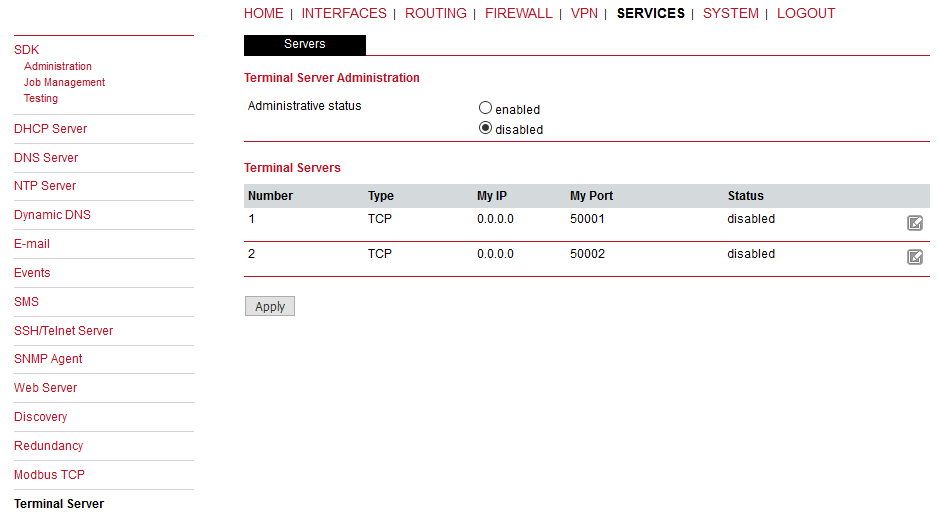
Administrative status | Enable or disable the feature |
If Enabled, 2 independent Terminal servers can be set up.
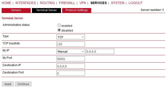
Administrative status | Enable or disable the particular TS |
Type | Set the TS Type – either TCP or UDP session |
TCP Timeout | If the Type is TCP, configure the required TCP timeout (i.e. close the TCP session if there is no communication for a given time period) |
My IP | IP address of M!DGE – usually Ethernet interface, but IP address of any interface can be used (pre-set IP address of given interface). “Manual” IP can also be filled. |
My Port | Set any listening TCP/UDP port (i.e. M!DGE listens for incoming connection on a given port). |
Destination IP | The destination IP address of TCP/UDP session (e.g. locally connected SCADA, virtual serial interface). IP address 0.0.0.0 can also be configured – any host can open the session with M!DGE. |
Destination Port | The destination port of TCP/UDP session. In some cases, applications dynamically change the IP port with each datagram. In such a case set Destination port=0. M!DGE will then send replies to the port from which the last response was received. This feature allows to extend the number of simultaneously opened TCP connections between a M!DGE and locally connected application to any value up to 10 on each Terminal server. |
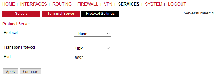
Protocol follows the same principles as a protocol on RS232 interface. The default UDP port is 8892 (transporting data usually over cellular network).
You can set up a voice gateway on the M!DGE2 router which can be used to connect mobile calls to VoIP clients and vice versa.
Administration:
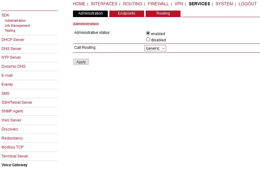
The following parameters can be used to set it up:
Administrative status | Specifies whether the gateway shall be enabled or disabled |
Call routing | Defines who will be responsible for call routing. If SDK has been specified you would need to install a script (see examples) which will be responsible for routing and accepting the calls. Otherwise the static routing configuration will be used. |
In case you are running multiple WWAN interfaces sharing the same SIM, please bear in mind that the system may switch SIMs during operation which will also result in different settings for voice communication.
Endpoints:
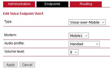
On this page you can activate the endpoints used for voice communication, the following types are supported:
Voice-Over-Mobile | Endpoint for GSM/UMTS/LTE calls (can be used for calls to mobile or landline phones) |
Nil-Device | A proforma Device to enable Call Signaling without Voice Support |
Based on your equipment, we recommend to adjust the modem’s audio profile for a better sound experience. The following profiles are available:
Handset | Provides a mild echo, short delay (less than 16-ms dispersion). This mode is intended for use with a well-designed handset, where the Echo Return Loss (ERL) is generally high. Full-duplex performance is easiest to achieve in this mode. |
Headset | Provides a moderate echo, short delay (less than 16-ms dispersion). This mode is intended for use in situations where the echo may be loud but low in delay. There are a variety of different headsets available with a wide variety of echo characteristics and noise pickup. Although the echo delay is typically short (< 16 ms) with all headsets, the echo return loss characteristics can vary significantly and are not well known a priori to the handset designer. This mode is more robust and more aggressive at echo cancellation. |
Speakerphone | Handle situations of loud echo with extreme acoustic distortion. This mode is intended for use with a car kit or speakerphone applications with high volume and high distortion. Acoustic echo in this situation has negative ERL and is impossible to cancel completely. It operates in a half-duplex manner and will be very aggressive in muting the entire signal to prevent any echo blips from being heard. |
Bluetooth/Carkit | Provides moderate echo, long delay (up to 64-ms dispersion). These modes are intended for bluetooth headsets and carkits which may have DSP processing on board and could give added delay to the system. |
Volume level | Specifies the modem’s volume level. 1 = low. 9 = high. |
Routing:
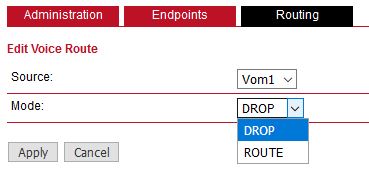
This page can be used to configure generic voice routing between the endpoints.
Enhanced routing facilities are provided via the SDK interface which is able to dispatch voice calls based on their attributes (such as phone number) and other system related status information (e.g. number/duration of calls per endpoint, registration status and so on). Using the SDK, you can also initiate or accept a call, adjust its volume level or do a hangup.
Anyway, for simple scenarios the generic method should be sufficient and can be configured as follows:
Source | Specifies the source endpoint (i.e. where the call comes in) |
Mode | The type of action which shall be applied for the call: DROP will silently hangup the call, ROUTE will route the call to the specified endpoint. Destination Specfies the target endpoint (i.e. where to call is routed to). |
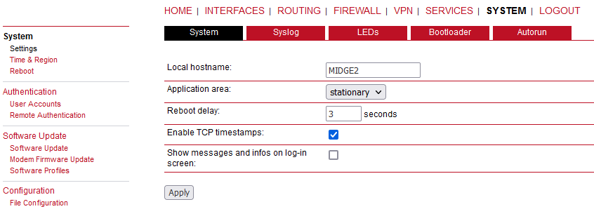
Local host name: | The local system hostname |
Application area: | The desired application area which influences the system behaviour such as registration timeouts when operating in the mobile environment. |
Reboot delay: | The number of seconds to wait before the reboot is initiated (might be needed for some system-rebooting events). |
Enable TCP timestamps: | Enable TCP timestamps for system wide TCP communication. This is needed for Protection Against Wrapped Sequence numbers (PAWS), but with these timestamps enabled a remote attacker can guess the uptime of the system. The uptime is a lower bound for the age of the main system components like the kernel. If the system has an uptime of 3 years, it’s unlikely that recent security patches were applied. |
Show messages and infos on log-in screen: | Show error messages and notifications on login screen. If this option is enabled, these messages are also shown before logging in with user credentials. |
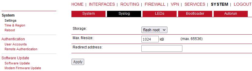
Storage: | The storage device on which logfiles shall be stored. Either internal flash root, or flash data. |
Max. filesize: | The maximum size of the logfiles (in kB) until they will get rotated. |
Redirect address: | Specifies an IP address to which log messages should be redirected to. A tiny system log server for Windows is included in TFTP32 which can be provided if requested. |
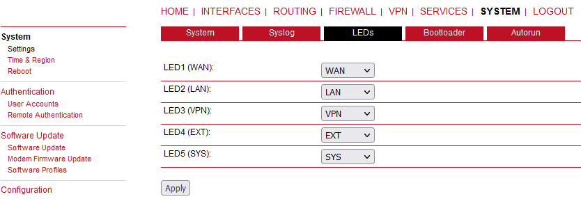
This menu allows to configure the behaviour of the LEDs on the front panel. The first LED (STAT) cannot be changed. A common settings for EXT LED is WWAN to show a signal strength.
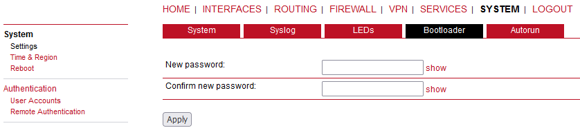
Password | The password used to unlock the bootloader. If empty, the admin password will be used. |
This feature can be used to automatically perform a software/config update as soon as an USB storage stick has been plugged in. Following files must exist in the root directory of a FAT16/32 formatted stick:
For authentication:
autorun.keyFor a software update:
sw-update.imgFor a configuration update:
cfg-<orSERIALNO>.zipcfg.zip
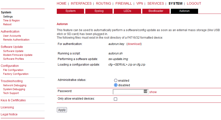
Administrative status: | Enable or disable autorun feature. |
Password: | Password for enabling autorun features. It can be set the same as the ‘admin’ password. |
Only allow enabled devices: | Check this if only enabled devices are allowed to proceed with autorun. |
The autorun.key file must hold valid access keys to perform any
actions when the storage device is plugged in. The keys are made up of your configured
password (SHA256). They can be generated and downloaded. You may also define multiple keys
in this file (line-after-line) in case your admin password differs if applied to multiple
M!DGE routers.
For new devices with an empty password the hash
key
e3b0c44298fc1c149afbf4c8996fb92427ae41e4649b934ca495991b7852b855
can be used.
The hash keys can be generated by running the command
echo -n
“<admin-password>” | sha256sum on a Linux system or an Internet hash key
generator (search for “sha-256 hash calculator”).
| Note | |
|---|---|
Units in complete factory state have Autorun feature enabled, using the hash key above. Once the ‘admin’ password is configured to access M!DGE unit, the Autorun feature is disabled until you set the Password within this menu. |
Network Time Protocol (NTP) is a protocol for synchronizing the clocks of computer systems over packet-switched, variable-latency data networks. M!DGE can synchronize its system time with an NTP server. If enabled, time synchronization is usually triggered after a WAN link has come up but before starting any VPN connections. Further time synchronizations are scheduled in the background every 60 minutes.
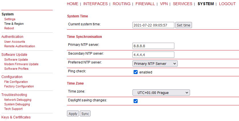
Current system time: | The current system time which can be synchronized against a valid NTP server or set manually. If manually set, the time is lost after the reboot. |
NTP server 1: | The primary NTP server IP address or hostname. |
NTP server 2 (optional): | The optional secondary NTP server IP address or hostname. |
Preferred NTP server: | Whether you prefer the 1st or 2nd NTP server. |
Ping check: | Uses an ICMP ping to check whether NTP servers are available when running initial time update. |
Time zone: | Time zone based on your geographical location. |
Daylight saving changes: | This option can be used to reflect daylight saving changes (e.g. switching from summer to standard time) depending on the selected time zone. |
will perform the time synchronization immediately.
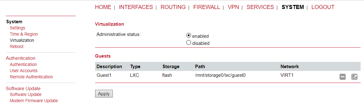
Virtualization gives customers the possibility to execute their own applications.
This page offers a simple shortcut to allow only secure connections (SSH, HTTPS) for managing the router. If the option “Secure authentication preferred” is set, users will be redirected to HTTPS but can still login via HTTP/telnet.
This page lets you manage the user accounts on the device.
The standard admin user is a built-in power user that has permission to access the Web Manager and other administrative services and is used by several services as the default user. Keep in mind that the admin password will be also applied to the root user which is able to enter a system shell. Any other user represents a user with lower privileges, for instance it has only permission to view the status page or retrieve status values when using the CLI.
The Web Manager supports up to 5 concurrent users with ‘user’ access rights (and only one Administrator). If login was successful, any duplicate users from other remote hosts will be logged out. Web interface is being blocked for 5 minutes after 10 failed login attempts.
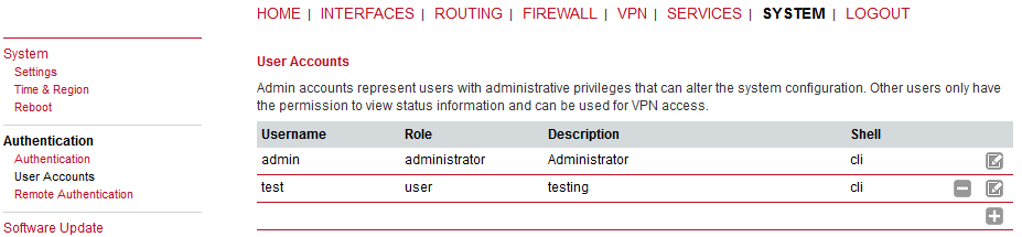
Username: | Define a user name. |
Description: | The user description. |
Role: | Either admin or user. |
Old password: | Enter the current password. |
New password: | Enter a new password. |
Confirm new password: | Enter a new password again to confirm correctness. |
| Note | |
|---|---|
When adding additional admin users you are required to provide the password of the default administrator. The user access management was improved in 4.4.40.104 firmware. It is now possible to grant native shell access to additional admin users or to disable shell access for a user. |
A remote RADIUS server can be used to authenticate users. This applies for the Web Manager and other services supporting and incorporating remote authentication.
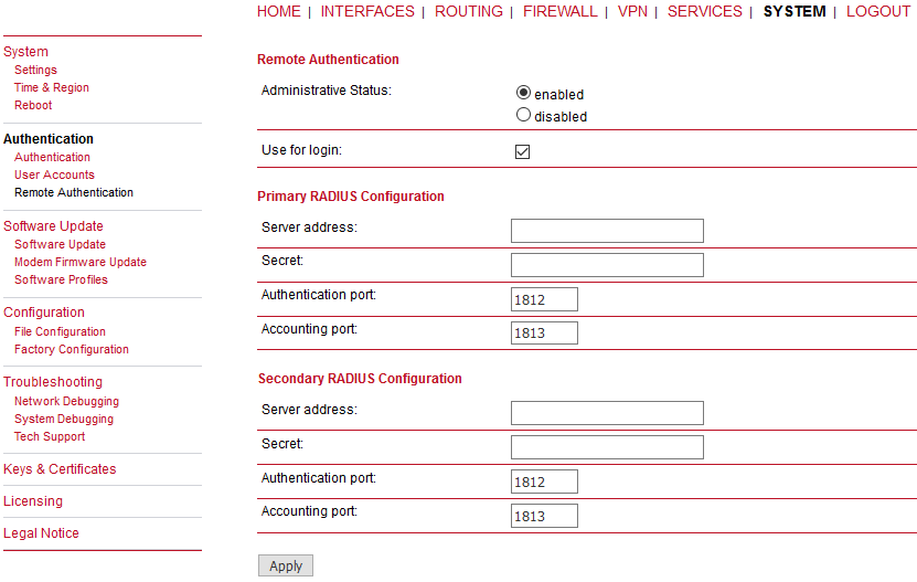
Administrative status: | Enable or disable remote authentication. |
Use for login: | This option enables remotely-defined users to access the Web Manager. |
Primary RADIUS configuration:
Server address: | RADIUS server address. |
Secret: | Secret used to authenticate against the RADIUS server. |
Authentication port: | Port used for authentication. |
Accounting port: | Port used for accounting messages. |
Secondary RADIUS configuration:
This is used if the first server is not available.
This menu can be used to run a manual software update.
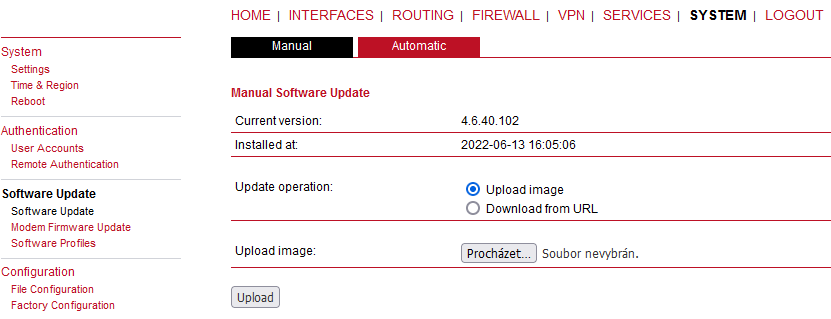
Update operation: | The update operation method being used. You can upload the image or download it from the given URL |
URL: | You can upload the image or download it from the given URL. |
When issuing a software update, the current configuration (including files like keys/certificates) will be backuped. Any other modifications to the filesystem will be erased. The configuration is generally backward-compatible. We also apply forward compatibility when downgrading to a previous software within the same release line, which is accomplished by sorting out unknown configuration directives which actually may lead to loss of settings and features. Therefore, it’s always a good idea to keep a copy of the working configuration. Generally, we do not recommend downgrading the software.
A software image can be either uploaded via the Web Manager or retrieved from a specific URL. It will be unpacked and deployed to a spare partition which gets activated if the update completed successfully. The whole procedure is accompanied by all green LEDs flashing up, the subsequent system reboot gets denoted by a slowly blinking Status LED. The backuped configuration will be applied at bootup and the Status LED will blink faster during this operation. Depending on your configuration, this may take a while.
| Note | |
|---|---|
Starting with SW release 4.2 we set default to not saving passwords; using password hashes instead. Storing passwords for users can be enabled, but is not recommended for new applications. Older SW releases require the passwords to be stored encrypted on the device. As we don’t have them any more in release version 4.2 and later you will have to provide the administrator password if you want to downgrade to a release 4.1.x and lower. The same passphrase will be used for bootloader login as well. All users which have no password stored on the device will not be able to login after downgrade until new passwords have been applied. |
| Important | |
|---|---|
Upgrade the Toby LTE module version to 17.00,A01.00 before updating M!DGE2 Software to 4.4.40.111. If installing 4.4.40.111 MIDGE2 software, make sure you have already upgraded Toby LTE module to newer version than 15.63 (i.e. 16.19,A01.02, 16.19,A01.04 or 17.00,A01.00)! Otherwise, the AT communication between M!DGE2 and the module stops working, which usually ends in a USB disconnection (i.e., MIDGE2/Toby LTE module cannot connect to cellular network). |
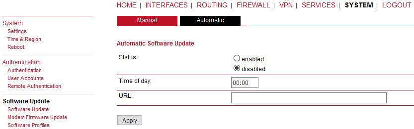
Status: | Enable/disable automatic software update |
Time of day: | Every day at this time M!DGE will do a check for updates |
URL: | The server URL where the software update package should be downloaded from. Supported protocols are TFTP, HTTP(s), and FTP |
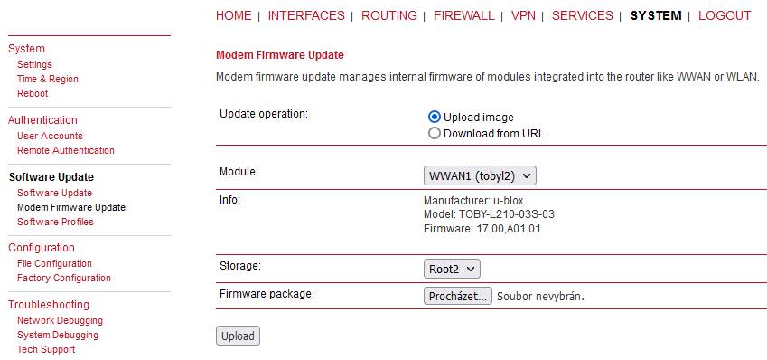
This menu can be used to perform a firmware update of a specific module.
Update operation: | The update operation method being used. You can upload a firmware package or download the files from a specific URL. |
Module: | The module which shall be updated. If you need to update the LTE module, select the WWAN1 module. In case you have M!DGE2 unit with two LTE modules, select WWAN2 for the 2nd LTE module. The file is usually in a .zip format – use it directly as this .zip file (do not unzip it for the update). |
Info: | Detailed module information (manufacturer, model, current firmware). |
Storage: | The temporary storage which shall be used for the update procedure. For boxes with limited amount of flash it is possible to use an USB stick which must be properly set up in the USB section and hold a proper filesystem such as ext4. |
Firmware package: | Select the desired firmware package (usually a .ZIP file). |
The maximum file size for WWAN firmware-update files was increased to 45 MB (since M!DGE2 software 4.4.40.107). This should be sufficient to perform most FW updates directly via web interface without the need for an external web or FTP server.
In every router you have two software profiles. One is active (currently used) and one is inactive. You can easily switch between these profiles any time.
It can be for example useful when there is some issue with the newest firmware and you need to restore the previous firmware version easily. Or you can just test some new features in the newest firmware and then get back to the previous one.
Configuration via the Web Manager becomes tedious for large volumes of devices. M!DGE therefore offers automatic and manual file-based configuration to automate things. Once you have successfully set up the system you can back up the configuration and restore the system with it afterwards. You can either upload a single configuration file (.cfg) or a complete package (.zip) containing the configuration file and a packed version of other essential files (such as certificates).
This section can be used to download the currently running system configuration (including essential files such as certificates).
The current configuration file is updated after every change and the time of this update is displayed along with a configuration version and a security hash. The current configuration can be updated manually by pressing the Apply button.
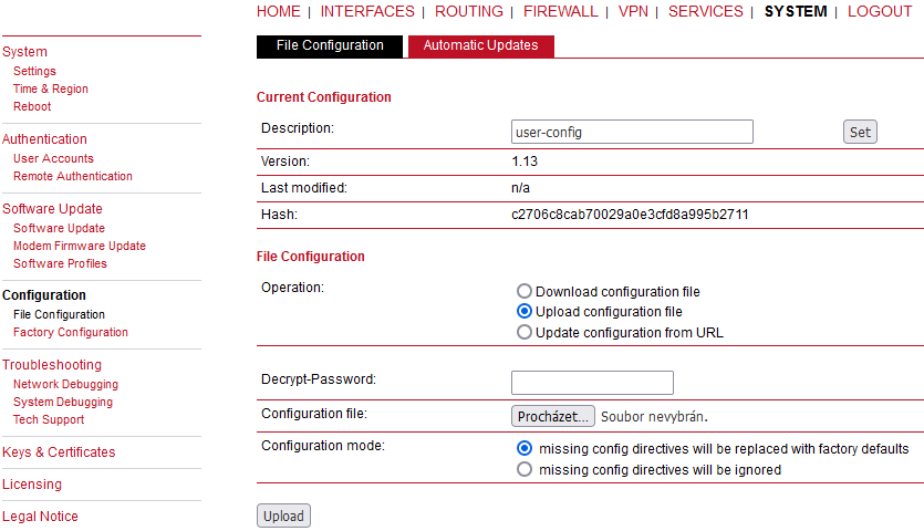
In order to restore a particular configuration you can upload a configuration previously downloaded or update configuration from the provided URL link.
You can choose between missing configuration directives stay the same as in the currently running configuration or be replaced with factory defaults.
A configuration file can be downloaded and encrypted with a password. When the file is uploaded, you need to provide this password to decrypt the file again.
Status: | Enable/disable automatic configuration update |
Time of day: | Time of day when the system will check for updates |
URL: | The server URL where the configuration file should be retrieved from (supported protocols are HTTP(s), TFTP, FTP) |
This menu can be used to reset the device to factory defaults. Your current configuration will be lost.
This procedure can also be initiated by pressing and holding the Reset button for at least 10 seconds. A successfully initiated factory reset can be noticed by all LEDs being turned on.
Factory reset will set the IP address of the Ethernet interface back to 192.168.1.1. You will be able to communicate again with the device using the default network parameters.
You may store the currently running configuration as factory defaults which will reside active even when a factory reset has been initiated (e.g. by your service staff). Please ensure that this corresponds to a working configuration. A real factory reset to the default settings can be achieved by restoring the original factory configuration and initiating the factory reset again.
| Important | |
|---|---|
If you store the currently running configuration as the factory defaults, have in mind that the password is also stored within this configuration. |
Various tools reside on this page for further analysis of potential configuration issues. The ping utility can be used to verify the remote host reachability.
Define the remote host (IP address or hostname), number of packets and the packet size.
The traceroute utility can be used to print the route to a remote host.
Define the target host (IP or hostname), Time-To-Live (TTL – number of hops on the resulting route) and the timeout in seconds (max. time to wait for the final respond).
The tcpdump utility generates a network capture (PCAP) of an interface which can be later analyzed with Wireshark. Interface can also be set as “ANY” to capture data from all available interfaces simultaneously.
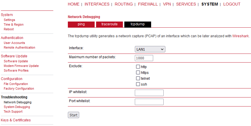
Several basic protocols can be excluded from the resulting PCAP file (HTTP, HTTPS, Telnet and SSH). Only specific IP addresses and/or ports can be captured.
| Note | |
|---|---|
The default number of received packets is set to 1000. For downloading the file, just click on the Download button. The captured file can be also downloaded from the /tmp/ directory via the appropriate file manager. |
Log files can be viewed, downloaded and reset here. Please study them carefully in case of any issues.
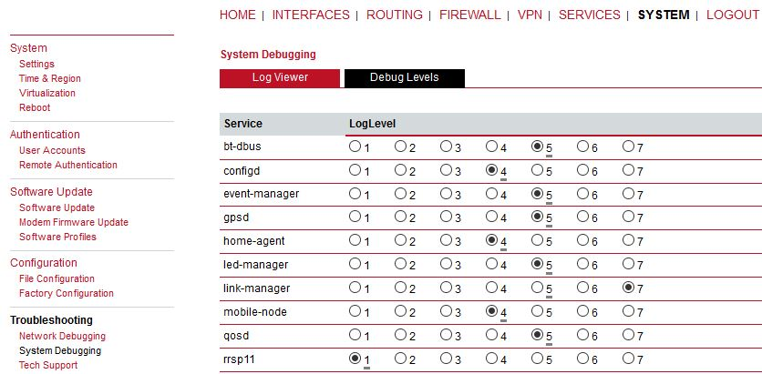
Default debugging levels for individual daemons are as follows:
bt-dbus – 5
configd – 4
event-manager – 5
gpsd – 5
home-agent – 4
led-manager – 5
link-manager – 5
mobile-node – 4
qosd – 5
rrsp11 – 1
rrsp12 – 1
rrsp2 – 1
rrsp21 – 1
sdkhost – 6
ser2net – 4
smsd – 5
surveyor – 5
swupdate – 5
ubxd – 5
voiced – 5
watchdog – 5
wwan-managerc – 5
wwanmd – 5
You can change the values to suit your needs and you can reset the values into their defaults by pressing the “Reset” button afterwards.
You can generate and download a tech support file here.
We strongly recommend providing this file when getting in touch with our support team, either by e-mail or via our online support form, as it would significantly speed up the process of analyzing and resolving your problem.
| Note | |
|---|---|
For both direct E-mail and Online support form a connection to the Internet has to be available. |
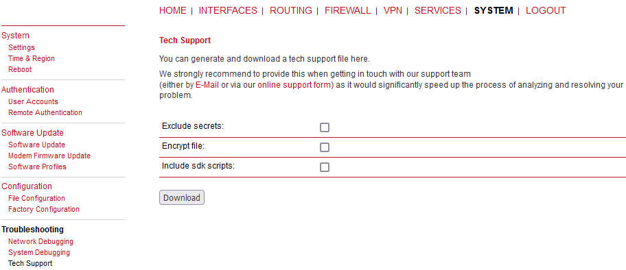
You can encrypt the Techsupport file in order to secure the file against reading it without knowing the security key for decrypting the file. It is more secure way to send the techsupport file via nonsecure e-mail. The decrypting key is known by our support team only and cannot be provided to anybody. Another option is to exclude secrets – passwords, credentials… But they are not readable in a plain text anyway. The last option is to include SDK scripts as well.
The key and certificate page lets you generate required files for securing your services (such as the HTTPS/WebServer and SSH server). Keep in mind that you will need to create keys and certificates for VPN or WLAN in case of certificate based authentication.
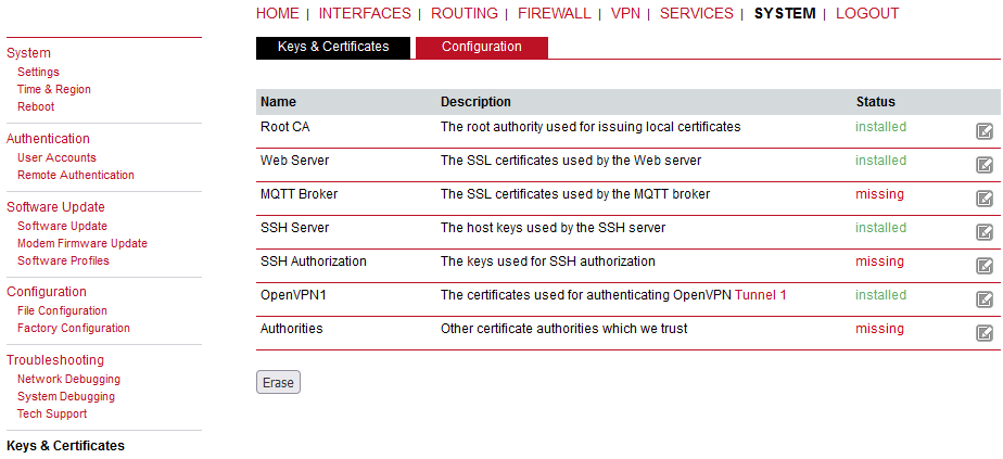
The entry pages shows an overview about installed keys and certificates. The following sections may appear:
Root CA: | The root Certificate Authority (CA) which issues certificates, its key can be used to certify it at trusted third party on other systems. |
Web Server: | The certificates for the Web server required for running HTTP over SSL (HTTPS). |
MQTT Broker: | The certificates for the MQTT Broker required for running MQTT over TLS encrypted connection. |
SSH Server: | The DSS/DSA keys for the SSH server. |
SSH Authorization: | The keys used for SSH authorization. |
OpenVPN: | Server or client keys and certificates for running OpenVPN tunnels. |
IPsec: | Server or client keys and certificates for running IPsec tunnels. |
WLAN: | Keys and certificates for implementing certificate-based WLAN authentication (e.g. WPA-EAP-TLS). |
Authorities: | Other certificate authorities which we trust when establishing SSL client connections. |
For each certificate section it is possible to perform the following operations:
generate locally: | Generate key and certificate locally on M!DGE |
upload files: | Key and certificate will be uploaded. We support files in PKCS12, PKCS7, PEM/DER format as well as RSA/DSS keys in OpenSSH or Dropbear format. |
enroll via SCEP: | Enroll key and certificate via SCEP |
download certificate: | Download key and certificate in ZIP format (files will be encoded in PEM format) |
create signing request: | Generate key locally and create a signing request to retrieve a certificate signed by another authority |
erase certificate: | Erase all keys and certificates associated with this section |
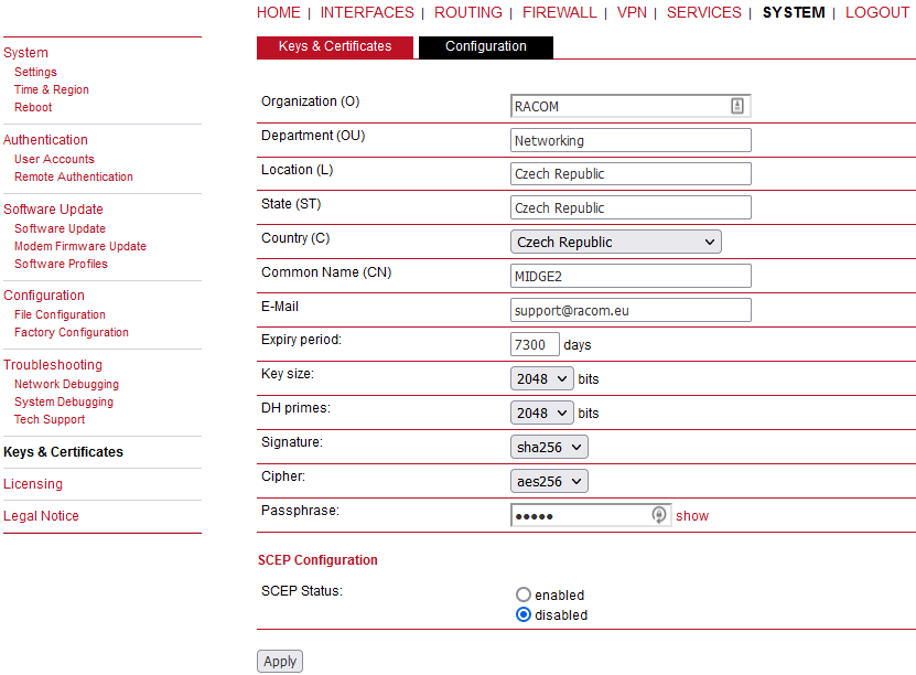
This page provides some general configuration options which will be applied when operating with keys and certificates. If keys, certificates and signing requests are generated locally, the following settings will be taken into account:
Organization (O): | The certificate owner’s organization |
Department (OU): | The name of the organizational unit to which the certificate issuer belongs |
Location (L): | The certificate owner’s location |
State (ST): | The certificate owner’s state |
Country (C): | The certificate owner’s country (usually a TLD abbreviation) |
Common Name (CN): | The certificate owner’s common name, mainly used to identify a host |
E-Mail: | The certificate owner’s email address |
Expiry period: | The number of days a certificate will be valid from now on |
Key size: | The length of the private key in bits |
DH primes: | The number of bits for custom Diffie-Hellman primes |
Signature: | The signature algorithm when signing certificates |
Cipher: | Choose a required Cipher |
Passphrase: | The passphrase for accessing/opening a private key. It is either a random passphrase (automatic) or user-specified one. |
Please be aware of the fact, that the local random number generator (RNG) provides pretty good randomness for most applications. If stronger cryptography is mandatory, we suggest to create the keys at an external RNG device or manage all certificates completely on a remote certification server. Nevertheless, using a local certificate authority can issue and manage all required certificates and also run a certificate revocation list (CRL).
When importing keys, the certificate and key file can be uploaded individually encoded in PEM/DER or PKCS7 format. All files (CA certificate, certificate and private key) can also be uploaded in one stroke by using the container format PKCS12. RSA/DSS keys can be converted from OpenSSH or Dropbear formats. It is possible to specify the passphrase for opening the private key. Please note that the system will generally apply the system-wide certificate passphrase on a key when installing the certificate. Thus, changing the general passphrase will result in all local keys getting equipped with the new one.
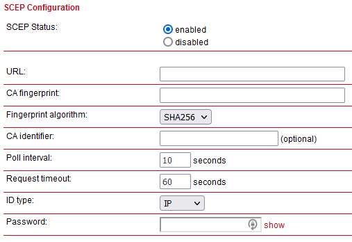
If certificates are getting enrolled by using the Simple Certificate Enrollment Protocol (SCEP) the following settings can be configured:
SCEP status: | Specifies whether SCEP is enabled or not. |
URL: | The SCEP URL, usually in the form http://<host>/<path>/pkiclient.exe. |
CA fingerprint: | The fingerprint of the certificate used to identify the remote authority. If left empty, any CA will be trusted. |
Fingerprint algorithm: | The fingerprint algorithm for identifying the CA (MD5 or SHA1). |
CA Identifier: | The Certification Authority issuer identifier (if SCEP server requires it). The CA Identifier is any string that is understood by the SCEP server (e.g. a domain name). |
Poll interval: | The polling interval in seconds for a certificate request. |
Request timeout: | The max. polling time in seconds for a certificate request. |
ID type: | It can be IP, Email or DNS. |
Password: | The password for the scep server. |
When enrolling certificates, the CA certificate will be initially fetched from the specified SCEP URL using the getca operation. It will be shown on the configuration page and it has to be verified that it belongs to the correct authority. Otherwise, the CA must be rejected. This part is essential when using SCEP as it builds up the chain of trust. If a certificate enrollment request times out, it is possible to re-trigger the interrupted enrollment request and it will be resumed using the previously generated key. In case a request has been rejected, you are required to erase the certificate first and then start the enrollment process all over again.
For SSL client connections (as used by SDK functions or when downloading configuration/software images) you might upload a list of CA certificates which are considered trusted. To obtain the CA certificate from a particular site with Mozilla Firefox, the following steps will be required:
Point the browser to the relevant HTTPS website
Click the padlock in the address bar
Click the More Information and the View Certificate button
Select the Details tab and press the Export button
Choose a path for the file (e.g. website.pem)
This menu allows you to view and update the license status of your system. Note that some features are disabled if no valid license is provided.
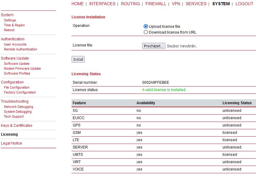
Availability means that the licence can be applied to the current hardware. The valid license is active if the status “licensed” is displayed in the respective line.
A dedicated GUI page under SYSTEM is pointing out that M!DGE contains in part open source software that may be licensed under GPL, LGPL or other open source licenses. It further provides detailed information for each package, including the relevant license text and the corresponding source URL. The user is now obliged to accept our end user license agreement during the initial setup of the router. We remind you that the source code of any package can be obtained by contacting our technical support at support@racom.eu.