M!DGE3 is a cellular router platform designed for any real-time environment. M!DGE3 cellular routers are native IP devices, with Linux OS that have been designed with attention to detail, performance and quality.
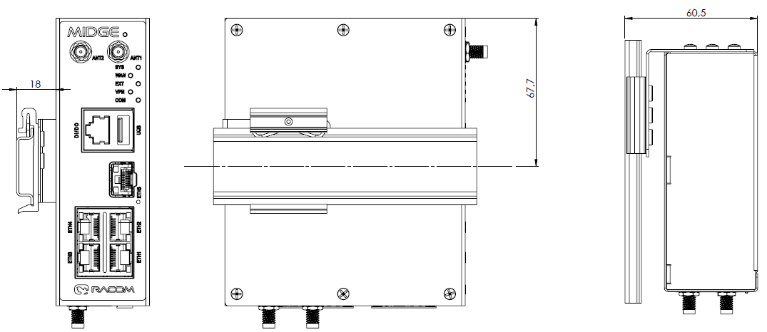
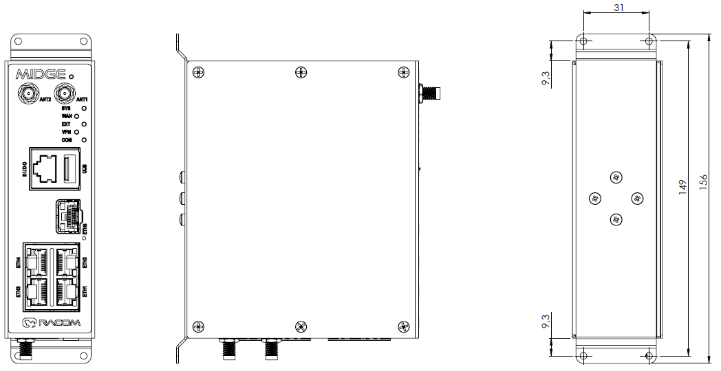
M!DGE3 is built into a rugged metal casing that allows for multiple installation possibilities, see Section 4.3, “Mounting”.
| Note | |
|---|---|
Variant M!DGE3e has some limitations in terms of HW interfaces and SW features. The details are mentioned in respective chapters / descriptions. |

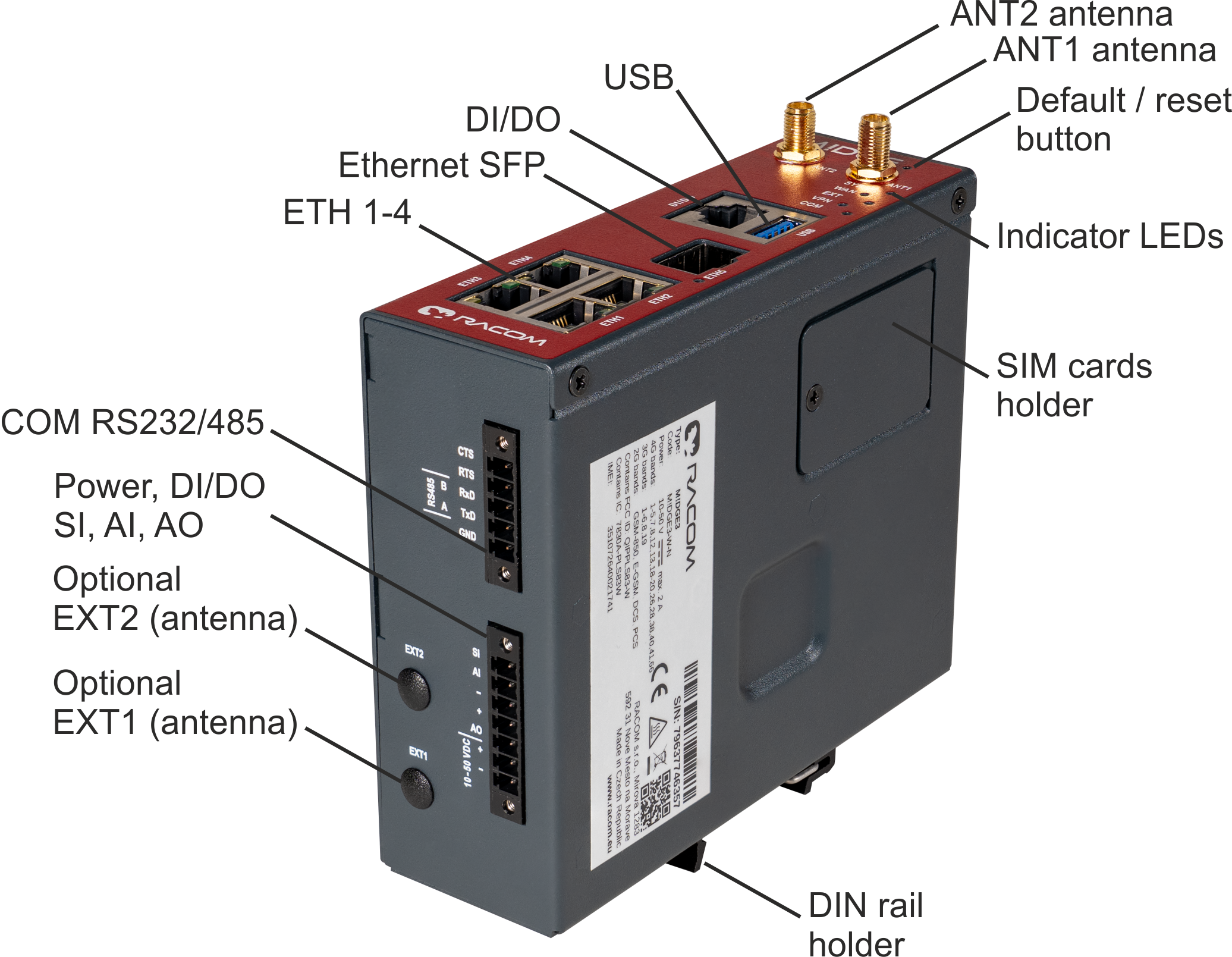
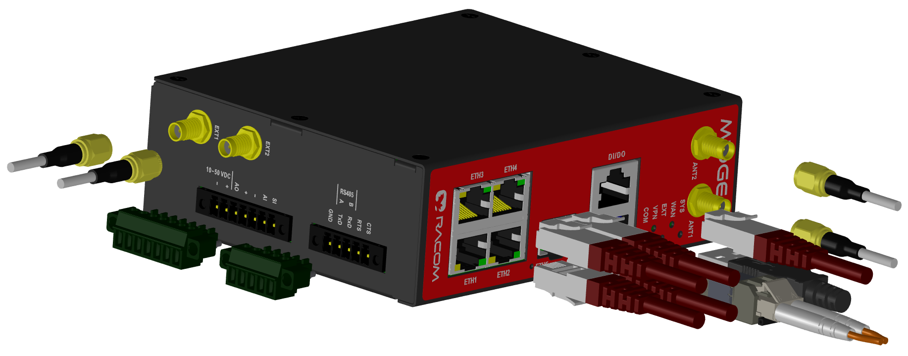
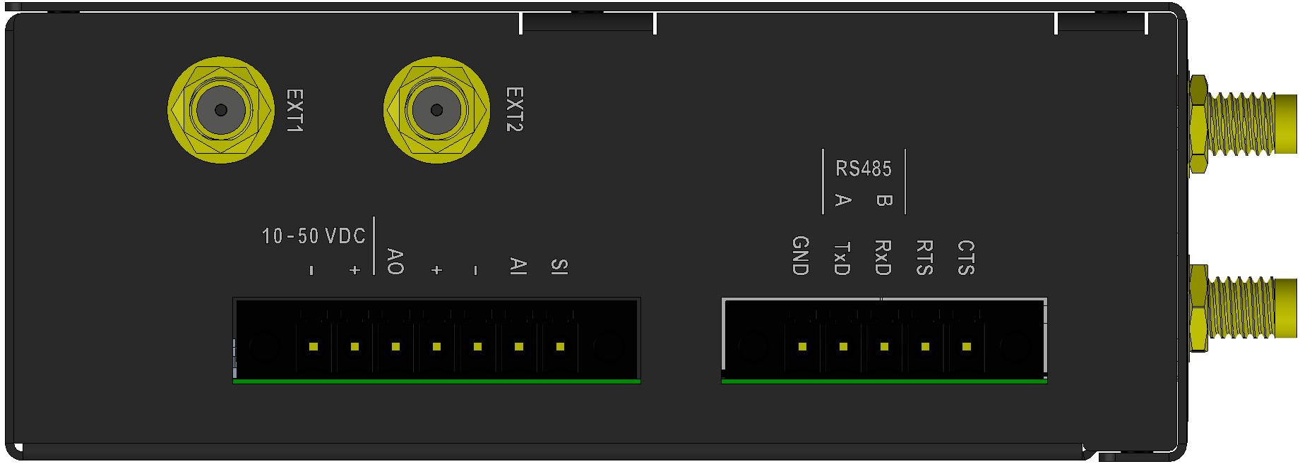
All connectors are located on the front and bottom panel. The front panel contains even LEDs. The HW button is located on the front panel as well (close to the upper edge).
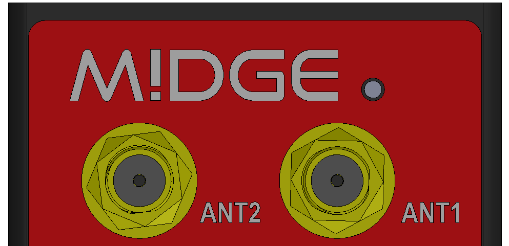
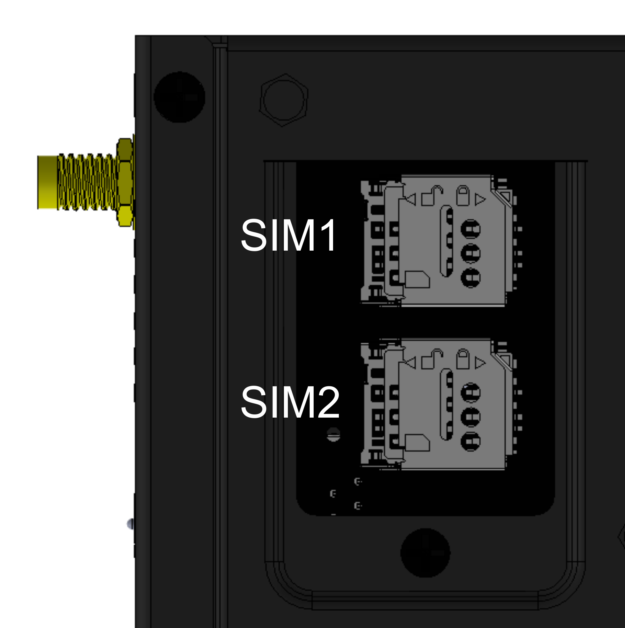
An antenna can be connected to M!DGE3 via SMA female 50 Ω connector.
M!DGE3 is equipped with two connectors. The ANT1 connector will be used for common transmitting and receiving. The ANT2 connector will be used as a Rx diversity connector.
| Note | |
|---|---|
For optimal LTE connection, using both antennas (Rx diversity) is recommended. If only one antenna is used, attach it to the ANT1 connector. |
| Warning | |
|---|---|
M!DGE3 cellular router may be damaged when operated without an antenna or a dummy load. |
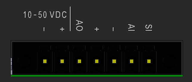
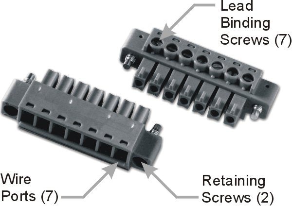
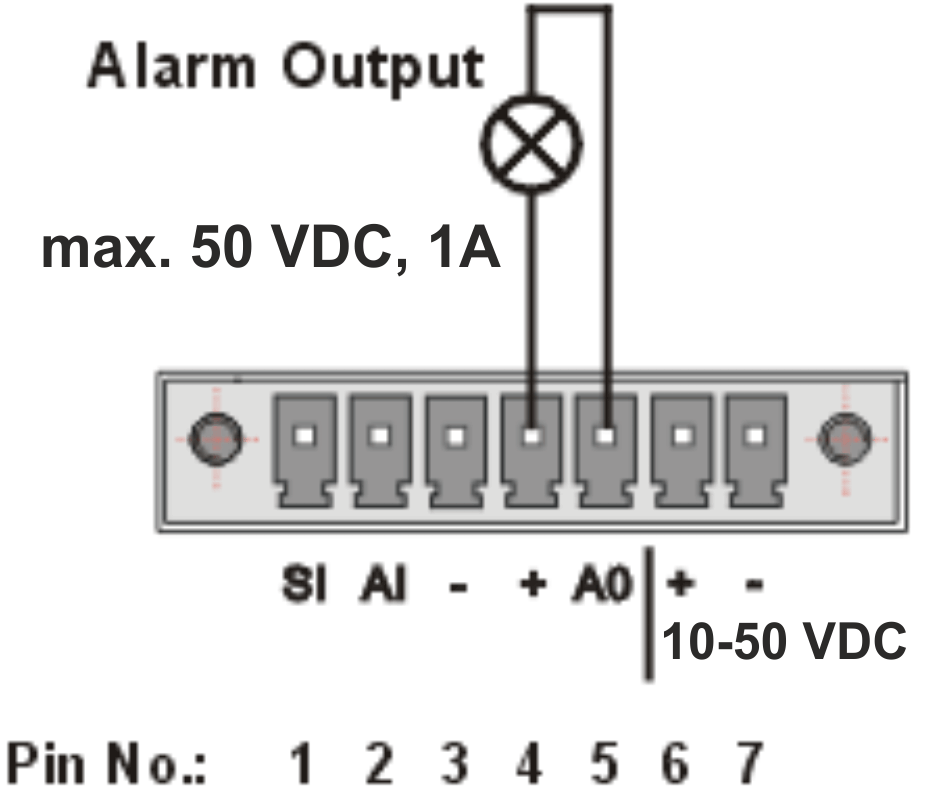
This rugged connector connects to a power supply and it contains control signals. A plug with screw-terminals and retaining screws for power and control connector is supplied with each M!DGE3. It is Tyco 7 pin terminal block plug, part No. 1776192-7, contact pitch 3.81 mm. The connector is designed for electric wires with a cross section of 0.5 to 1.5 mm2. Strip the wire leads to 6 mm (1/4 inch). Isolated cables should receive PKC 108 or less end sleeves before they are inserted in the clip. Insert the cables in the wire ports, tightening securely.
Tab. 2.1: Pin assignment
| Pin | Labeled | Signal |
|---|---|---|
| 1 | SI | SLEEP INPUT
|
| 2 | AI | HW ALARM INPUT
|
| 3 | − | −(GND) – for SLEEP IN, HW ALARM INPUT |
| 4 | + | +(POWER) – for HW ALARM OUTPUT |
| 5 | AO | HW ALARM OUTPUT open drain output max. 50 VDC, 1 A |
| 6 | + | + POWER (10 to 50 V) Undervoltage threshold 8.5 VDC Overvoltage threshold 55 VDC |
| 7 | − | − POWER (GND) |
Pins 3 and 7 are connected internally.
Pins 4 and 6 are connected
internally.
Minus pole (GND) is internally connected with casing.
|
HW ALARM INPUT HW ALARM INPUT is a digital input. If grounded (e.g. by connecting to pin 3), an external alarm is triggered. |
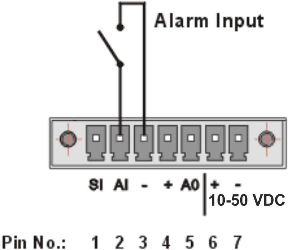 |
|
HW ALARM OUTPUT HW ALARM OUTPUT is a digital output. |
 |
POWER
The POWER pins labelled + and – serve to connect a power supply 10–50 VDC. The requirements for a power supply are defined in Section 4.8, “Power supply” and Chapter 9, Technical parameters.
Standard RJ45 connectors for Ethernet connection. M!DGE3 has 10/100/1000Base-T Auto MDI/MDIX interfaces so it can connect to 10 Mb/s, 100 Mb/s or 1000 Mb/s Ethernet network. The speed can be selected manually or recognized automatically by M!DGE3. M!DGE3 is provided with Auto MDI/MDIX function which allows it to connect over both standard and cross cables, adapting itself automatically.
| Note | |
|---|---|
M!DGE3e has only 2 ETH ports. |
Pin assignment
Tab. 2.2: Ethernet to cable connector connections
| Pin | Signal | Direct cable | Crossed cable | |
|---|---|---|---|---|
| 1 | TX+ | orange – white | green – white |
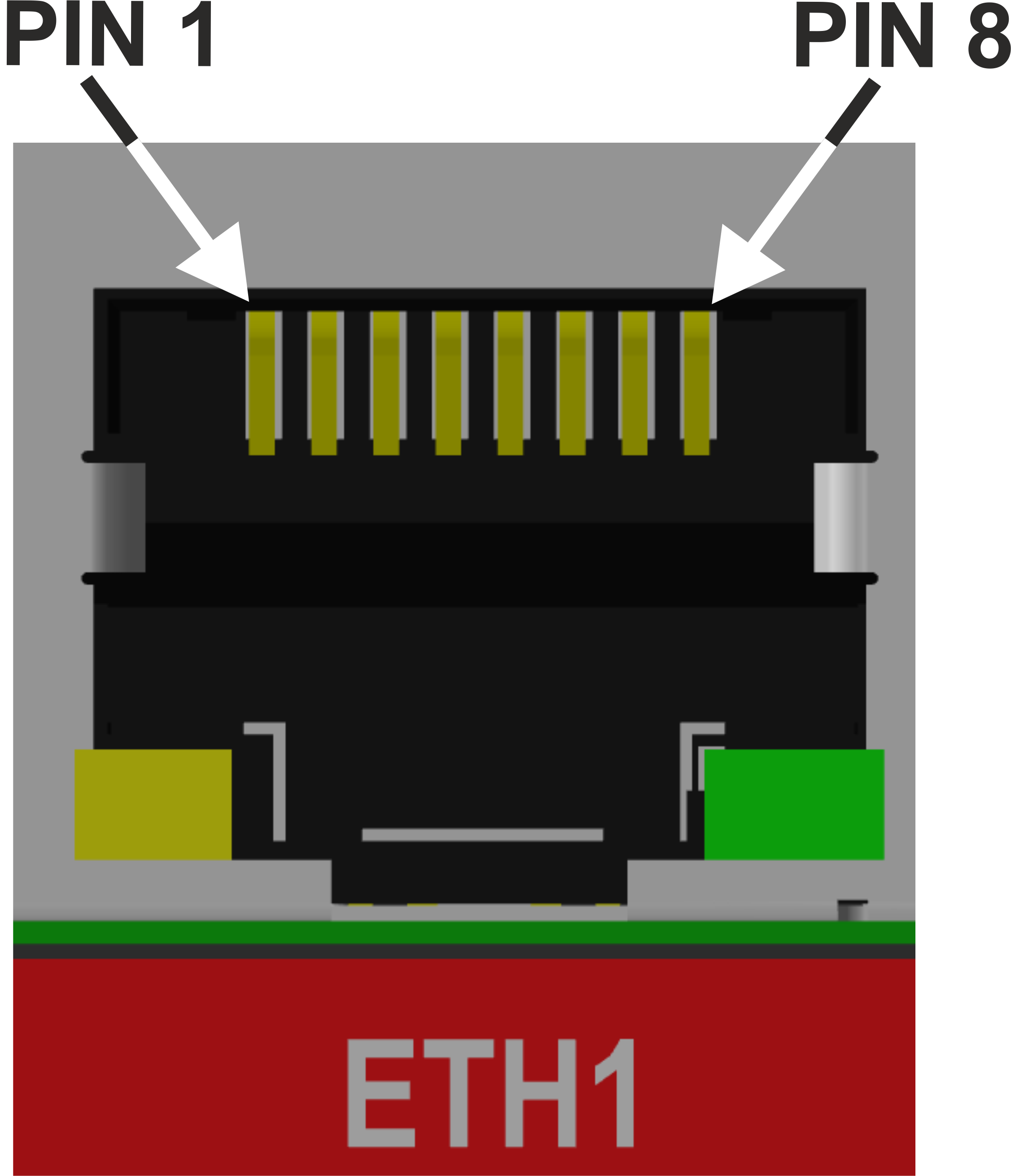 |
| 2 | TX- | orange | green | |
| 3 | RX+ | green – white | orange – white | |
| 4 | — | blue | blue | |
| 5 | — | blue – white | blue – white | |
| 6 | RX- | green | orange | |
| 7 | — | brown – white | brown – white | |
| 8 | — | brown | brown |
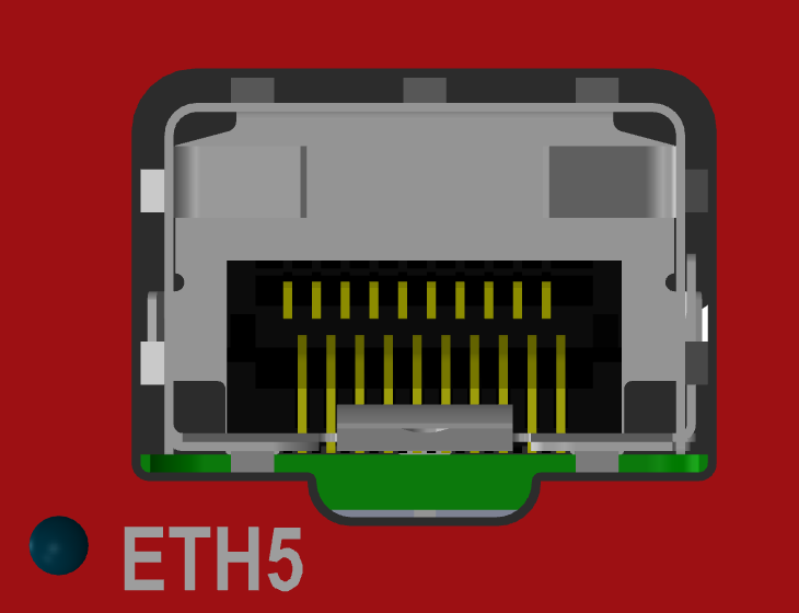
ETH5 is a standard SFP slot for 10/100/1000 Mb/s Ethernet SFP modules, user exchangeable
with maximal power consumption 1.25 W. Both fibre optic and metallic Ethernet SFP modules
are supported. For optical both single and dual mode fibre optics Ethernet modules (= 2 or 1
fibers) can be used. CSFP modules are not supported.
offers all
mentioned types of SFP modules, tested to be M!DGE3 compatible as a standard
accessory.
The SFP status LED is located just next to the slot. It is controlled by SFP module. Its function is specific for each SFP module. The typical behavior is an indication the received signal from the fibre optic or metallic link to be within operational range.
| Important | |
|---|---|
It is strongly recommended to use a high quality SFP module with industry temperature range. The SFP modules listed in Accessories are thoroughly tested by and are guaranteed to function with M!DGE3 units. It is possible to use any other SFP module, but cannot guarantee they will be completely compatible with M!DGE3 units. |
| Note | |
|---|---|
M!DGE3e has no SFP port. |
M!DGE3 provides serial interface COM terminated by 5 pin terminal connector which is supplied with each M!DGE3 unit. It can be configured as RS232 or RS485. It is Tyco 5 pin terminal block plug, part No. 1776192-5, contact pitch 3.81 mm. The connector is designed for electric wires with a cross section of 0.5 to 1.5 mm2. Strip the wire leads to 6 mm (1/4 inch). Isolated cables should receive PKC 108 or less end sleeves before they are inserted in the clip. Insert the cables in the wire ports, tightening securely.
RS232 of M!DGE3 is a hard-wired DCE (Data Communication Equipment) device. Equipment connected to the serial port of M!DGE3 unit should be DTE (Data Terminal Equipment).
RS485 of M!DGE3 is not galvanic isolated and it is not terminated.
Tab. 2.3: COM pin description (except variant M!DGE3-x-x-D)
| Terminal block | COM – RS232 | COM – RS485 | |||
|---|---|---|---|---|---|
| Pin | Signal | In / Out | Signal | In / Out |
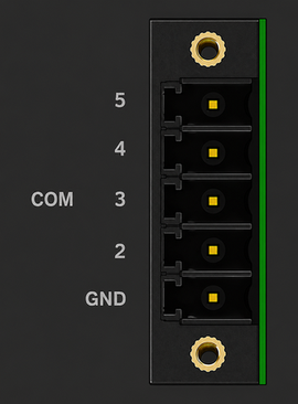 |
| 5 | CTS | Out | — | ||
| 4 | RTS | In | — | ||
| 3 | RxD | Out | line B | In/Out | |
| 2 | TxD | In | line A | In/Out | |
| 1 | GND | GND | |||
Tab. 2.4: COM pin description (variant M!DGE3-x-x-D)
| Terminal block | COM1 – RS232 | COM1 – RS485 | COM2 –
RS232 (optional) | ||||
|---|---|---|---|---|---|---|---|
| Pin | Signal | In / Out | Signal | In / Out | Signal | In / Out |
|
| 5 | CTS | Out | — | RxD | Out | ||
| 4 | RTS | In | — | TxD | In | ||
| 3 | RxD | Out | line B | In/Out | — | ||
| 2 | TxD | In | line A | In/Out | — | ||
| 1 | GND | GND | GND | ||||
| Note | |
|---|---|
COM2 on the 5 pin terminal connector is available with the M!DGE3-x-x-D hardware version. The “M!DGE3-SW-COM2” software key must be installed to unlock COM2. Switching between RS232 and RS485 mode is only possible on the COM1 port. COM2 can only be used if COM1 is set to RS232 (not RS485). |
| Note | |
|---|---|
Extension module ‘C’ allows to expand the unit by two additional RS232 serial ports. In the current firmware version it is not supported on HW which already provides COM2 in the basic version (Var. D). Module description can be found in section 2.4.4 COM2 – COM3. |
M!DGE3 uses USB 3.0, Host A interface. USB interface is wired as standard:
Tab. 2.5: USB A Pinout Cable Assembly
| Pin | Signal | Wire | |
|---|---|---|---|
| 1 | VBUS | Red |
 |
| 2 | D- | White | |
| 3 | D+ | Green | |
| 4 | GND | Black | |
| 5 | StdA_SSRX- | Blue | |
| 6 | StdA_SSRX+ | Yellow | |
| 7 | GND_DRAIN | GROUND | |
| 8 | StdA_SSTX- | Purple | |
| 9 | StdA_SSTX+ | Orange | |
| Shell | Shield | Connector Shell |
The USB interface is designed for the connection to an external ETH/USB adapter or a Wi-Fi adapter. There are optional accessories to M!DGE3, for more details see here. The adapters are used for service access to web configuration interface of M!DGE3 unit.
The USB connector also provides power supply (5 V / 0.5 A). It can be used to temporarily power a connected device, for instance a telephone. The USB connector should not be used as permanent source of power supply.
Tab. 2.6: Digital Inputs and Outputs
| Pin | Description | Signal | |
|---|---|---|---|
| 1 | DI1+ | Digital input (differential) – Positive – (P) |
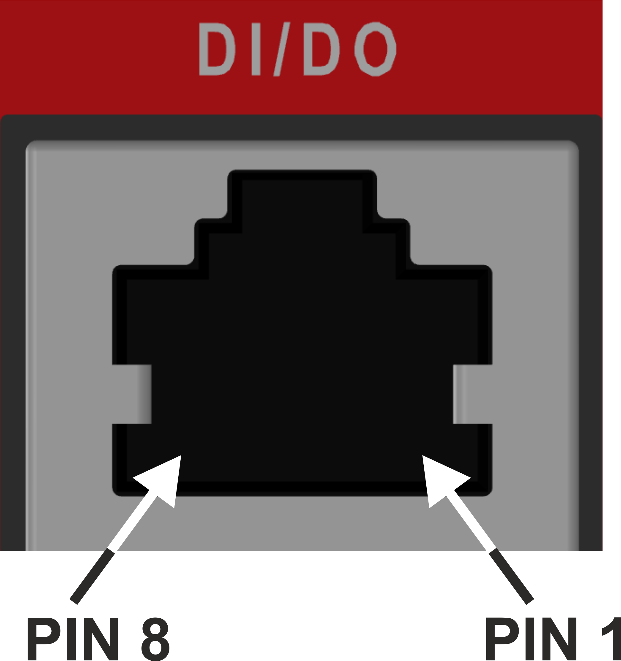 |
| 2 | DI1- | Digital input (differential) – Negative – (N) | |
| 3 | GND | Ground | |
| 4 | DO1 |
Digital Output 1 | |
| 5 | DO2 |
Digital Output 2 | |
| 6 | GND | Ground | |
| 7 | DI2 | Digital Input 2 | |
| 8 | DI3 | Digital Input 3 |
Digital Outputs:
Open drain output max. 50 VDC, 0.2 A
Isolated differential digital input:
Input voltage difference (P-N) > 1.9 VDC Logic “H”
Input voltage difference (P-N) < 1.1 VDC Logic “L”
Maximum differential voltage 50 V
Digital inputs:
Schmitt-triggered inverted input
Pull below 1.1 VDC to activate (1.1 VDC / 1.9 VDC threshold hysteresis)
Max. 50 VDC
![[Note]](/images/radost/images/icons/note.png)
Note M!DGE3e has no dedicated DI/DO connector.
| Note | |
|---|---|
These Digital Inputs and Outputs cannot be used if the unit is equipped with the ‘C’ Expansion module providing additional serial ports. |

HW button is placed on the right side of M!DGE3, next to the logo.
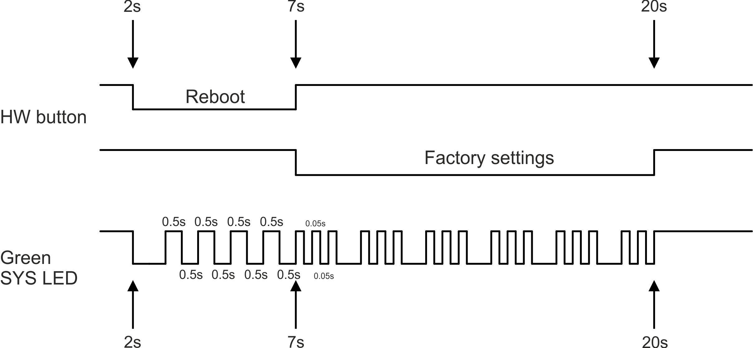
HW button operation
Press less than 2 seconds – Nothing happens
Press from 2 up to 7 seconds – Reboot is performed on button release
Press from 7 up to 20 seconds – Factory settings are performed on button release
Press more than 20 seconds – Nothing happens
LEDs indicator is placed on M!DGE3’s front panel.
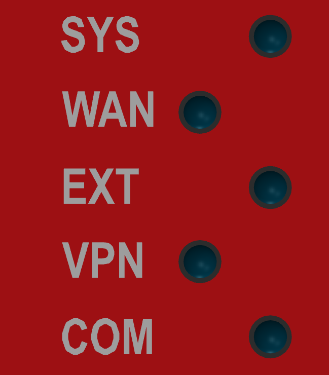
Tab. 2.7: Key to LEDs
| LED | Colour | Status | Function |
|---|---|---|---|
| SYS | Green | Permanently lit | System OK |
| Flashing – period 500 ms | Reset button pushed | ||
| Three fast (50 ms) flashes – pause (500 ms) | Reset button factory reset | ||
| Flashing regularly – period 2000 ms | Sleep mode activated | ||
| Red | Permanently lit | Alarm | |
| Flashing regularly – period 500 ms | Serious system error | ||
| Orange | Permanently lit | Unit booting | |
| Three fast (75 ms) flashes | USB flash disc inserted | ||
| Flashing fast (75ms) – period 1000 ms | Interaction with USB flash disc | ||
| Green / Orange | Flashing regularly – period 300 ms | FW activation – do not shut down the device | |
| WAN | Green / Orange / Red | Permanently lit, or flashing in 1 sec intervals |
Permanently lit – connected to the cellular network. Color signalizes signal strength Flashing – connecting into the cellular network. |
| EXT | Green | Permanently lit |
Activity of mPCIe connected equipment (like GPS fix, LTE connected, …) |
| Red | Permanently lit |
Alarm of mPCIe connected equipment | |
| Table of Signal levels for individual services for cellular interface | |||
| Table of GNSS activity | |||
| VPN | Green | Permanently lit | When all configured servers and clients are UP (listening or connected). |
| Flashing regularly | When at least one server or client is UP (listening or connected) and at least one server or client is DOWN (not listening or not connected). | ||
| Yellow | Permanently lit | When all servers and all clients are DOWN | |
| Not lit | – | When neither server nor client is set. | |
| COM | Green | Permanently lit | Data receiving |
| Orange | Permanently lit | Data transmitting | |
- Alarm
An Alarm is triggered by any event with severity Error or higher (see Section 8.4, “Events”).
M!DGE3 cellular router can be delivered with additional (optional) second cellular module, GPS extension or COM extension. In case of Cellular or GPS it comes with two additional SMA connectors installed on the bottom panel (EXT1, EXT2). Activity of any extension module is signalized on M!DGE3’s front panel (EXT LED).
| Note | |
|---|---|
No extensions are available fot M!DGE3e version. |
It is recommended to use both antennas (Rx diversity) for the LTE connection. In case of using only one antenna, attach it to the EXT1 connector. The EXT1 connector is used for both transmitting and receiving, or for single-antenna setups. The EXT2 connector is specifically for Rx diversity.
When the 2nd cellular module is used, LED behavior of this extension is signalized by Green / Orange / Red LED
Permanently lit – Connected to the cellular network (color signalize signal strength)
Flashing in 1 sec interval – Connecting into the cellular network
M!DGE3 cellular router can be delivered with the Wi-Fi extension.
M!DGE3 cellular router can be equipped with the GPS receiver with time pulse output. EXT1 connector is used for connection of the active GPS antenna, EXT2 connector is used for the precise time pulse output.
The 2nd and 3rd COM ports are available when the Extension module ‘C’ (2× RS232) is installed. In such a case: The DI/DO connector is used as a connector for COM2 and COM3.
COM2 and COM3 parameters:
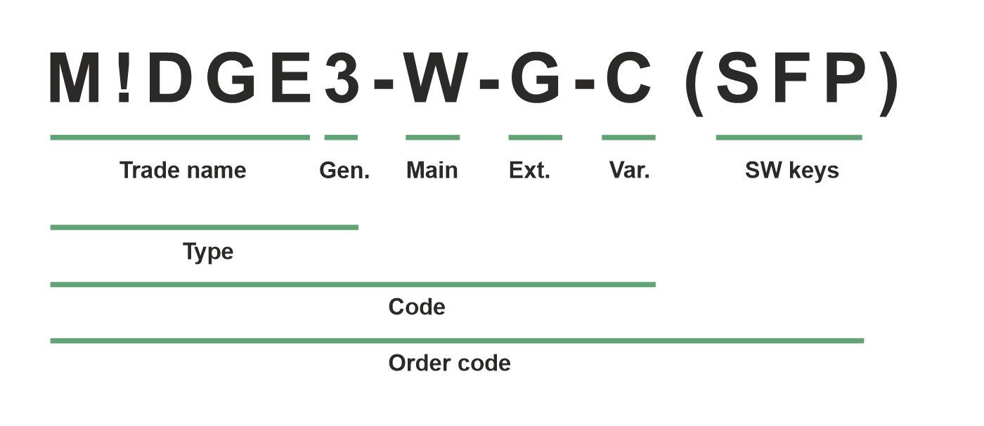
Trade name – trade and marketing name of the product. This name is used for all products within the same product family.
Possible values: M!DGE
Gen. – generation of the product of specific Trade name. The very first generation does not have any number in this position.
Possible values: 3
Main
Ext. – Extension module embedded in mPCIe slot
Possible values:
N – not used
W – Extension cellular module; Part No.: mPCIe-W
Bands W – 4G/3G/2G, GlobalR – Extension cellular module; Part No.: mPCIe-R
Bands R – LTE Cat M1/NB1/NB2, LatAm, Europe (incl. 410 MHz, 450 MHz)S – Extension cellular module; Part No.: mPCIe-S
Bands S – LTE Cat M1/NB1/NB2, GlobalG – Extension GPS (GNSS) module; Part No.: mPCIe-GPS
C – Extension 2× RS232; Part No.: mPCIe-COMS
F – Extension Wi-Fi module; Part No.: mPCIe-WIFI
Note Only one option for mPCIe slot is possible
Legacy values:
M – Extension cellular module M; Part No.: mPCIe-M.
O – Extension cellular module O; Part No.: mPCIe-O.
Var. – Hardware variant
Possible values:
C – M!DGE3e (essential version)
D – M!DGE3, two serial ports available (2× RS232 / 1× RS485), only available with main module R or S, combination with extension module C is not possible
O – M!DGE3, Digital inputs and outputs DI1, DI2, DI3, DO1, DO2 never possible (this variant is available on special request only)
SW keys – if unit is ordered with SW keys, all keys are specified in this bracket. SW key can be ordered independently for specific S/N anytime later on.
Possible values:
SFP – enables SFP interface; Part No.: M!DGE3-SW-SFP
Type – specific product type
Possible values:
M!DGE3
Code – part of order code which is printed on Product label on the housing (SW keys are not HW dependent and can be ordered later on, so they are not printed on Product label).
Order code – the complete product code, which is used on Quotations, Invoices, Delivery notes etc.
In order to find out the correct Order code, please use E-shop.