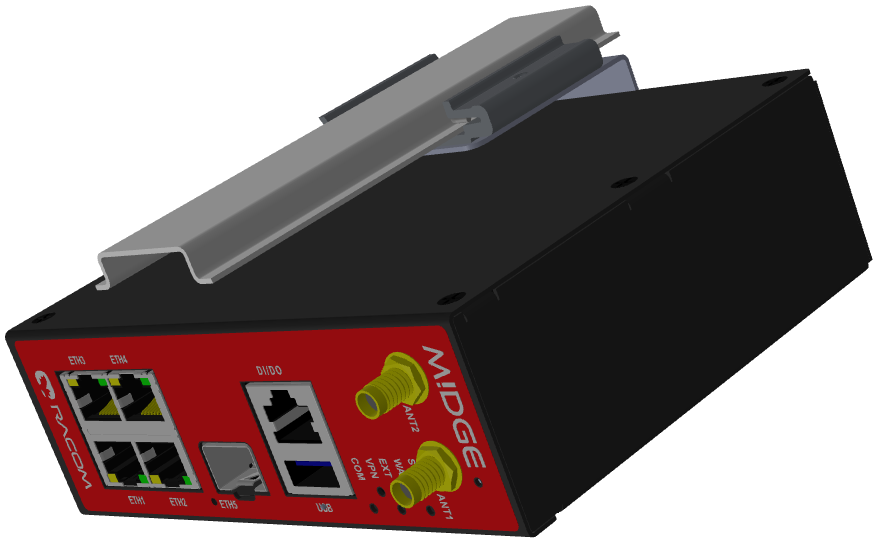
Mount M!DGE3 into cabinet (Section 4.3, “Mounting”).
Install antenna (Section 4.4, “Antenna installation”).
Install feed line (Section 4.5, “Antenna feed line”).
Ensure proper grounding (Section 4.6, “Grounding”).
Run cables and plug-in all connectors except from the SCADA equipment (Section 2.2, “Connectors”).
Apply power supply to M!DGE3.
Connect configuration PC (Midge3 “Connecting”).
Configure M!DGE3.
Test radio link quality (e.g. using Monitoring tool).
Connect the SCADA equipment.
Test your application.
Enter the PIN code for the particular SIM card, if required (SETTINGS > Interfaces > Cellular > SIM1/SIM2).
Enable and Configure the Access Point Name (APN) (SETTINGS > Interfaces > Cellular > MAIN/EXT > Enable & Add/Edit Cellular profile).
Add default route 0.0.0.0/0 via WWAN (MAIN or EXT) (SETTINGS > Routing > Static) or other routing rule required.
No route is added automatically, required routes must be added manually.
Without such routes, unit will be connected to the cellular network, but not communicating with any other device/IP.
Save the changes.
Check functionality
SETTINGS > Interfaces > Cellular > Status > Show more (<)
DIAGNOSTICS > Tools > ICMP ping
DIAGNOSTICS > Statistics > Cellular statistic tables (Interface, State, Signal)
In case of any issues, download a detailed Diagnostic package (DIAGNOSTICS > Information > Diagnostic package), include all the information except User credentials and send it to support@racom.eu.
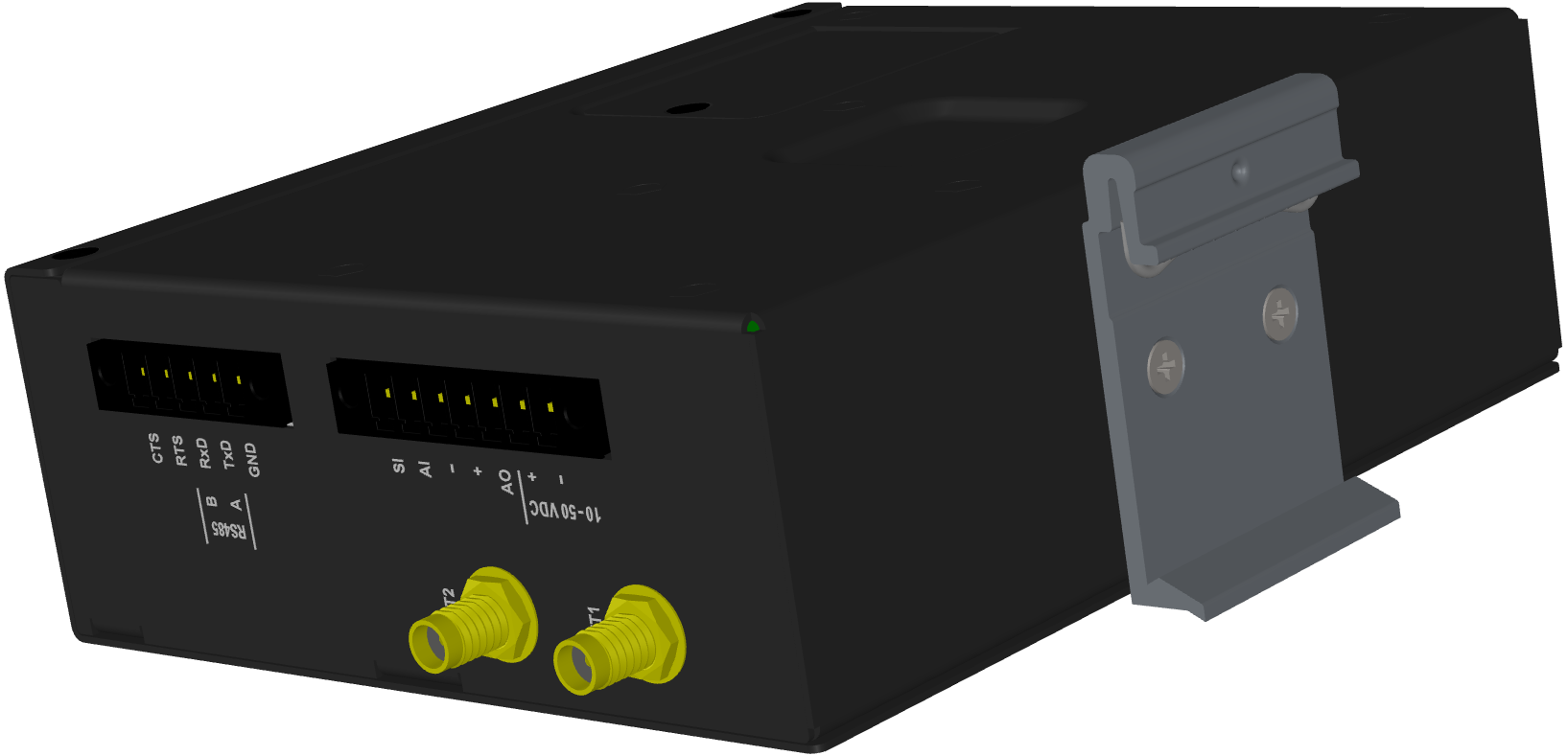
M!DGE3 cellular modem is directly mounted to the DIN rail by a holder (which comes with the modem).
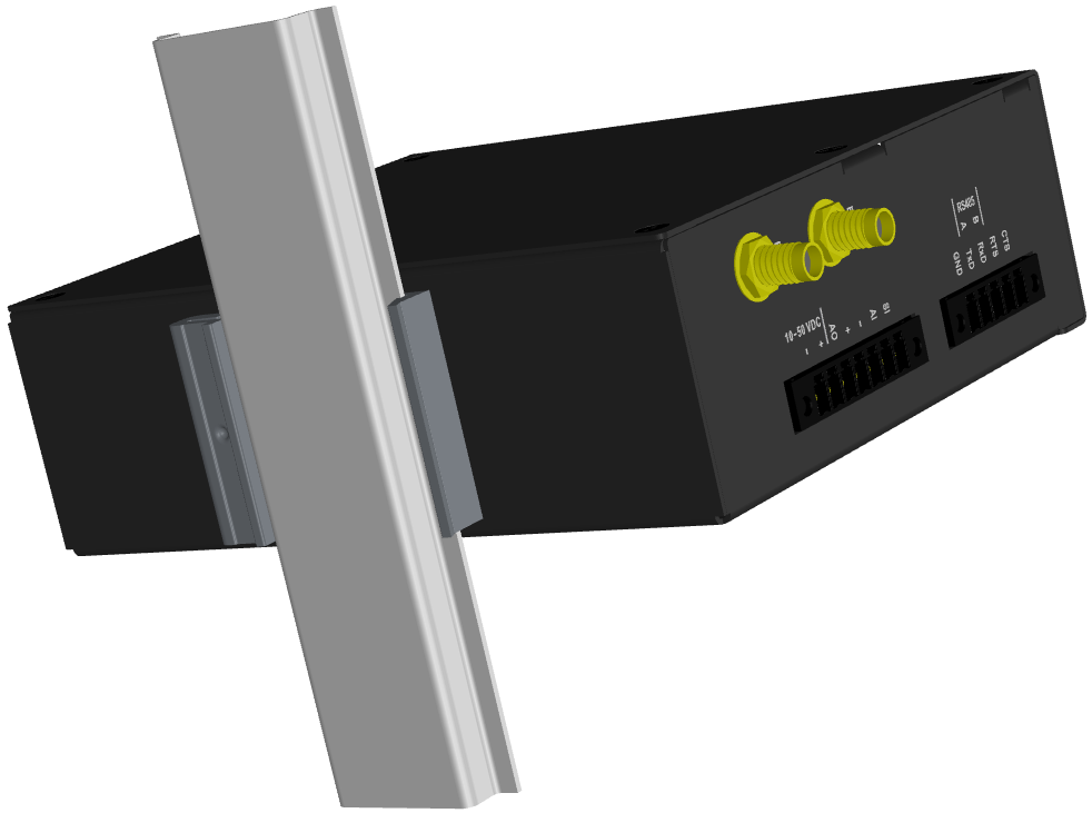
Using this mounting M!DGE3 can be mounted in different angles (by 90° clockwise/counter clockwise).
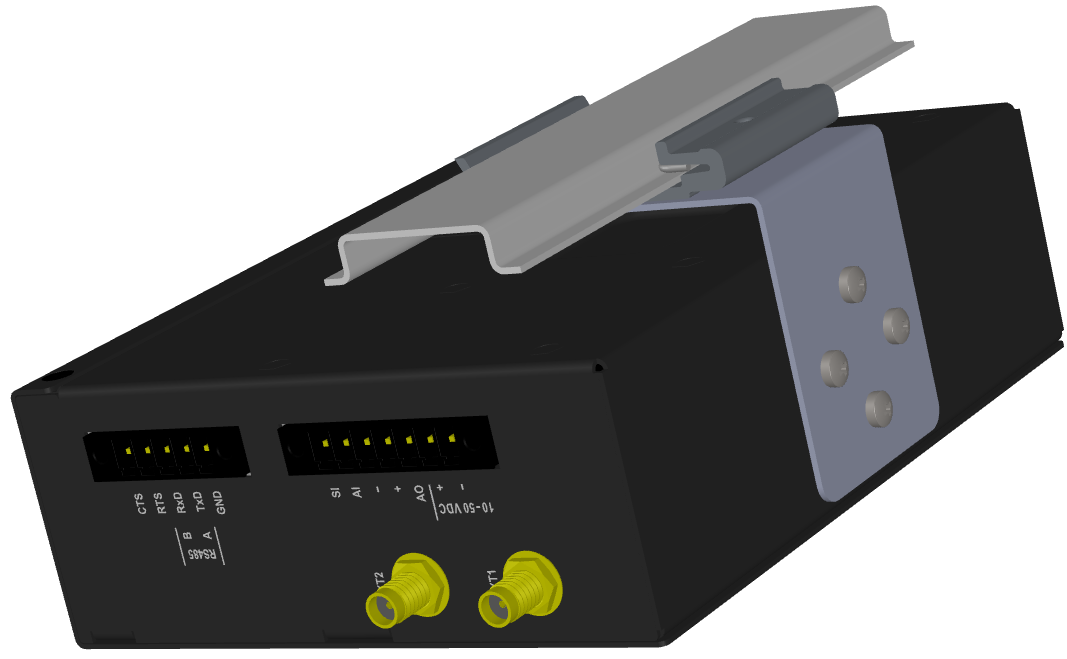
For edged mounting to the DIN rail, Edge-bracket (optional accessory) is used. Use
solely the
M4×5 mm screws that are supplied.
The type of antenna best suited for the individual sites of your network depends on the layout of the network and your requirements for signal level at each site.
The antenna should never be installed close to potential sources of interference, especially electronic devices like computers or switching power supplies.
Additional safety recommendations
Only qualified personnel with authorization to work at heights are entitled to install antennas on masts, roofs and walls of buildings. Do not install the antenna in the vicinity of electrical lines. The antenna and brackets should not come into contact with electrical wiring at any time.
The antenna and cables are electrical conductors. During installation electrostatic charges may build up which may lead to injury. During installation or repair work all open metal parts must be temporarily grounded.
The antenna and antenna feed line must be grounded at all times.
Do not mount the antenna in windy or rainy conditions or during a storm, or if the area is covered with snow or ice. Do not touch the antenna, antenna brackets or conductors during a storm.
The antenna feed line should be chosen so that its attenuation does not exceed 3 to 6 dB as a rule of thumb. Use 50 Ω impedance cables only.
The shorter the feed line, the better. If M!DGE3 is installed close to antenna, the data cable can be replaced by an Ethernet cable for other protocols utilizing the serial port, see Section 7.1.3, “Terminal servers”.
Always follow the installation recommendations provided by the cable manufacturer (bend radius, etc.). Use suitable connectors and install them diligently. Poorly attached connectors increase interference and can cause link instability.
To minimize the odds of the transceiver and the connected equipment receiving any damage, a safety ground (NEC Class 2 compliant) should be used, which bonds the antenna system, transceiver, power supply, and connected data equipment to a single-point ground, keeping the ground leads short.
The M!DGE3 cellular router is generally considered adequately grounded if the supplied flat mounting brackets are used to mount the cellular router to a properly grounded metal surface. If the cellular router is not mounted to a grounded surface, you should attach a safety ground wire to one of the mounting brackets or a screw on cellular router’s casing.
If the antenna is installed outside the building, it is strongly recommended to install an appropriate lightning protection system where the antenna cable enters the building.
| Note | |
|---|---|
All cabling, groundings and lightning protection must comply with the applicable standards and regulations. |
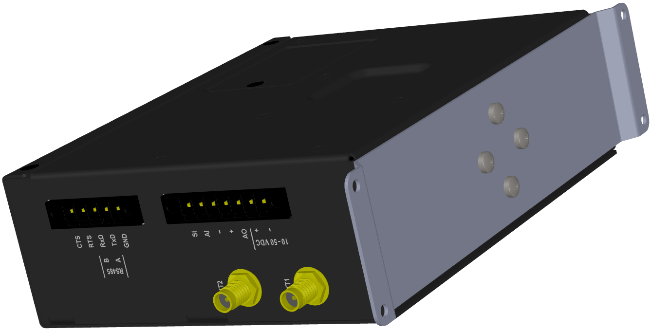
M!DGE3 uses standard connectors. Use only standard counterparts to these connectors.
You will find the pin-outs of connectors in Section 2.2, “Connectors”.
We do not recommend switching on power supply of the M!DGE3 unit before connecting the antenna and other devices. Connecting the RTU and other devices to M!DGE3 while powered increases the likelihood of damage due to the discharge of difference in electric potentials.
M!DGE3 may be powered from any well-filtered 10 to 50 VDC power source. To avoid radio channel interference, the power supply must meet all relevant EMC standards. Never install a power supply close to the antenna. Connector (- pins) is internally connected to the casing of the M!DGE3 unit.