The Settings chapter contains a description of all configuration parameters of the unit. The division into chapters corresponds to the menu structure in the graphical web interface. The Help pages, which are built into the unit firmware, are identical to this chapter of the manual.
M!DGE3 provides 5 physical Ethernet ports ETH1, ETH2, ETH3, ETH4 and ETH5. ETH1 – ETH4 ports are metallic. ETH5 port is an SFP port. There is a possibility to define an Ethernet bridge – a logical Network interface – by bridging (joining) together multiple physical Ethernet interfaces. All interfaces bridged together share the same traffic.
The Network interface (technically – an Ethernet bridge) is identified by a name. The name always begins with a “LAN-” prefix. Multiple Network interfaces can be defined. Multiple physical Ethernet interfaces can be bridged together by using single Network interface.
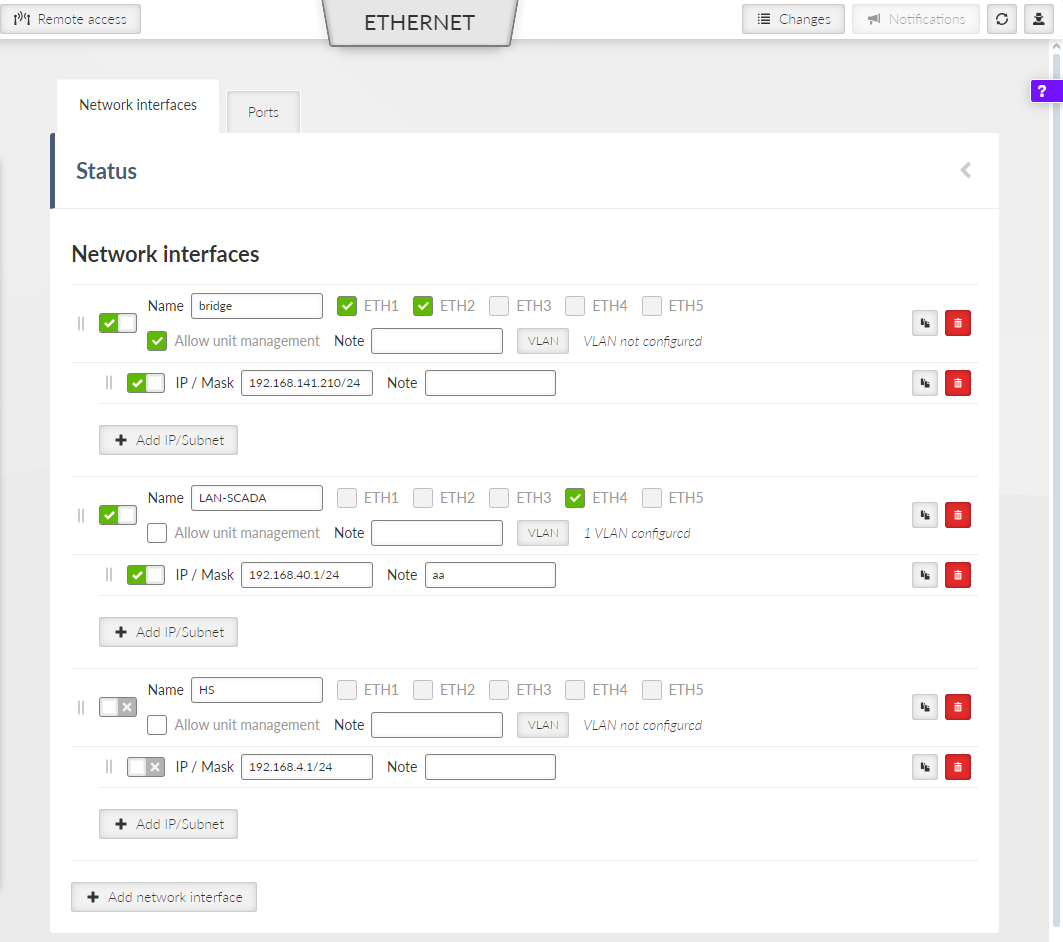
The cellular unit default setting bridges all Ethernet ports together. New Network interfaces can be defined to split the Ethernet traffic of the individual ports. Any single Ethernet port can be detached from an existing Network interface and added to another Network interface.

Single or multiple Ethernet subnets can be defined within one Network interface. Each subnet is identified by its IP / mask. Use the optional parameter Note to keep your network configuration in human readable manner.
- Enable / Disable
Checkbox {On, Off}
Toggle your network interface status.
- Name
Text input
Enter a unique identifier for your network interface.
- ETH1 – ETH5
Checkboxes
Assign specific Ethernet ports to your network interface.
![[Note]](/images/radost/images/icons/note.png)
Note Hardware option M!DGE3e product variants H and J provide only ETH1 and ETH2 interfaces.
Note Your interface does not require assigned Ethernet ports if you configure a GRE L2 tunnel.
- Allow unit management
Checkbox {On, Off}
Permit administration access to your station through this interface.
- MTU mode
List box {Automatic, Limited}, default = “Automatic”
Select your interface MTU calculation method. Automatic sets the MTU based on your subordinate ports. Limited restricts the MTU to your specified upper boundary.
- MTU limit [B]
Number [74, 1500], default = “1500”
Set your upper MTU boundary. The system applies this value when you select the Limited MTU mode. Your actual interface MTU decreases if your subordinate ports have a smaller MTU.
- Add IP/Subnet
Button
Add a defined subnet to your network interface.
- IP / Mask
IP address/Mask
Enter the IP address and mask in CIDR notation. This address identifies your network interface in the Layer 3 network.
- Note
Text input
Add a custom description for your interface.
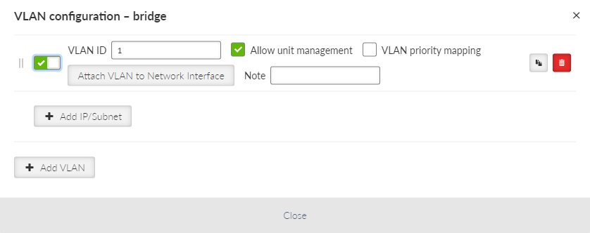
- VLAN
Each Network interface can have one or more attached VLANs with one or more Subnets.
- Enable / Disable
Enables / disables VLAN.
- VLAN ID
Number {0 – 4094}, default = 1
Specifies the VLAN ID according to IEEE 802.1Q
- Allow unit management
Allows / denies unit management for the specific VLAN. This switch is not connected with the Network interface switch with the same name, so only this VLAN can be used for diagnostics.
- VLAN priority mapping
Relates to QoS
- Attach VLAN to Network interface
Attaches VLAN to the defined network interface
- MTU mode
List box {Automatic, Limited}, default = “Automatic”
Select your interface MTU calculation method. Automatic sets the MTU based on your subordinate ports. Limited restricts the MTU to your specified upper boundary.
- MTU limit [B]
Number [74, 1500], default = “1500”
Set your upper MTU boundary. The system applies this value when you select the Limited MTU mode. Your actual interface MTU decreases if your subordinate ports have a smaller MTU.
- Note
Optional comment.
- Add IP/Subnet
Adds defined subnet to the VLAN.
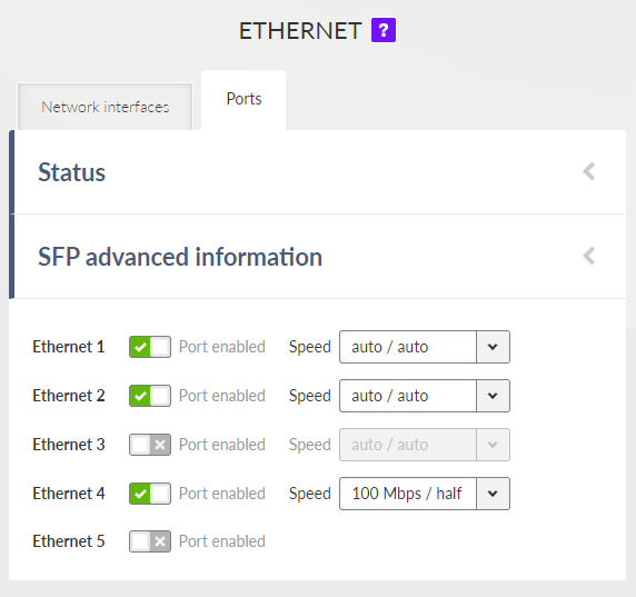
- Enable / Disable
Enables / Disables ETH ports (1 – 5) SW control.
- ETH1 – ETH4 speed
List box {auto / auto; auto / full; auto / half; 1000 Mbps / auto; 1000 Mbps / full; 1000 Mbps / half; 100 Mbps / auto; 100 Mbps / full; 100 Mbps / half; 10 Mbps / auto; 10 Mbps / full; 100 Mbps / half}, default = “auto / auto”
Defines the speed and half / full duplex traffic.
Note HW option M!DGE3e (product variant ‘H’ and ‘J’) provides only ETH1 – ETH2 interfaces.
| Note | |
|---|---|
When several bridges are interconnected in the network, it is appropriate to switch on Spanning Tree Protocol (ADVANCED > Interfaces > Ethernet > STP) to prevent bridge loops and build a loop-free logical topology. |
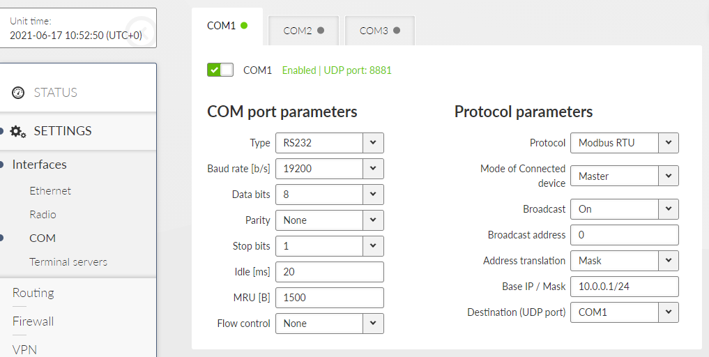
Data incoming to the M!DGE3 unit from the COM port are received by the Protocol module. The Protocol module behavior depends on the Protocol selected. the incoming frame from the COM port is processed by the Protocol module, translated into UDP frame, forwarded to the M!DGE3 router module and further processed according to router rules. Such UDP frames received by the M!DGE3 unit from the M!DGE3 network (based on the unit IP address and UDP port of the Protocol module) are translated into original frame format (by the Protocol module) and send out through the COM port.
When extension module “C” is installed, two additional COM ports (RS232) are available. Their setting is similar to the COM1 port.
The menu is divided to two parts:
This settings of Baud rate, Data bits, Parity and Stop bits of COM port and setting of connected device must match.
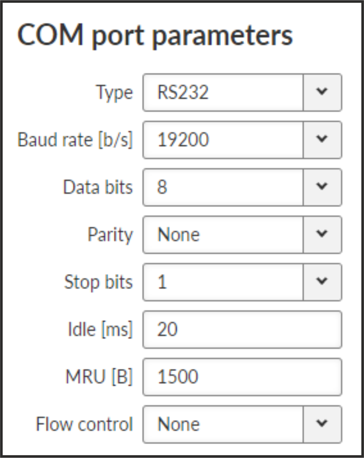
- Type
List box {possible values}, default = “RS232”
COM port can be configured to either RS232 or RS485.
- Baud rate [b/s]
List box {standard series of rates from 600 to 1152000 b/s}, default = “19200”
Select Baud rate from the list box: 600 to 1152000 b/s rates are available.
Serial ports use two-level (binary) signaling, so the data rate in bits per second is equal to the symbol rate in bauds.
- Data bits
List box {5; 6; 7; 8}, default = 8, for COM3 (optional) only 8
The number of data bits in each character.
- Parity
List box: {None; Odd; Even}, default = “None”
Wikipedia: Parity is a method of detecting errors in transmission. When parity is used with a serial port, an extra data bit is sent with each data character, arranged so that the number of 1-bits in each character, including the parity bit, is always odd or always even. If a byte is received with the wrong number of 1-bits, then it must have been corrupted. However, an even number of errors can pass the parity check.
- Stop bits
List box {1; 2 (1.5)}, default = 1, for COM3 (optional) only 1, for 5 data bits the 1.5 length of stop bits is used instead of 2
Wikipedia: Stop bits sent at the end of every character allow the receiving signal hardware to detect the end of a character and to resynchronize with the character stream.
- Idle [ms]
Number {10 – 16383}, default = 20
This parameter defines the maximum gap (in milliseconds) in the received data stream. If the gap exceeds the value set, the link is considered idle, the received frame is closed and forwarded to the network.
- MRU [B]
Number {1 – 2047}, default = 1500
MRU (Maximum Reception Unit) — an incoming frame is closed at this size even if the stream of bytes continues. Consequently, a permanent data stream coming to a COM results in a sequence of MRU-sized frames sent over the network.
Note 2. This MRU and the MTU in Cellular settings are independent, however MTU should be greater or equal to MRU.
- Flow control
List box {None; RTS/CTS}, default = “None”
RTS/CTS (Request To Send / Clear To Send) hardware flow control (handshake) between the DTE (Data Terminal Equipment) and M!DGE3 (DCE – Data Communications Equipment) can be enabled in order to pause and resume the transmission of data. If RX buffer of M!DGE3 is full, the CTS goes down.
Note RTS/CTS Flow control requires a 5-wire connection to the COM port.
- Buffer flush time [ms]
Number {0 – 65535}, default = 0
This parameter can be used to prevent unwanted deadlock of the serial communication. The timer is reset by every received or transmitted packet over the COM port. When the timer expires, the protocol status is reset and the packet buffer is cleared. Setting parameter to 0 disables the feature. This parameter is available only via ADVANCED menu.
Each SCADA protocol used on serial interface is more or less unique. The COM port protocol module performs conversion to standard UDP datagrams to travel across M!DGE3 Cellular network. The same settings are valid for Terminal servers as well (for more details about TS see Section 7.1.3, “Terminal servers”).
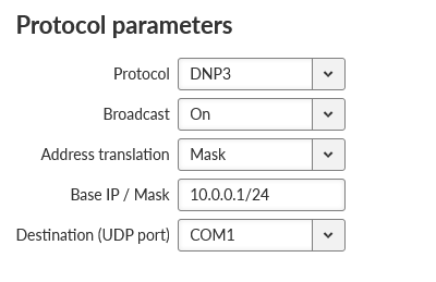
- Protocol
List box {None; Async Link; COMLI; DNP3; DF1; IEC101; Mars-A; Modbus RTU; PR2000; RDS; S3964R; SAIA S-BUS; UNI}, default = “None”
- Address translation
List box {Mask; Table}, default = “Mask”
SCADA protocol address is translated to the IP address using either Mask (common rule for all addresses) or Table (specific rule per address) type of conversion
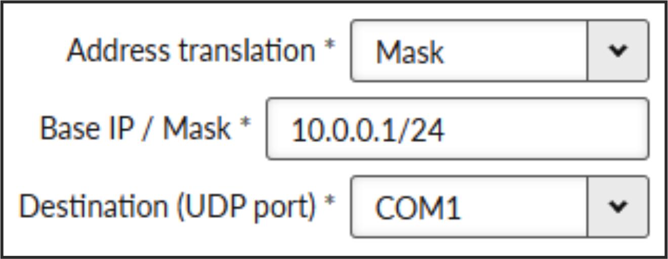
- Base IP / Mask
A part of Base IP address defined by this Mask is replaced by ‘Protocol address’. The SCADA protocol address is typically 1 byte long, so Mask 24 (255.255.255.0) is most frequently used. This IP address is used as a destination IP address of the UDP datagram into which the serial SCADA packet received from COM is encapsulated.
- Destination UDP port
List box {Manual; COM1 – COM3; TS1 – TS5}, default = “COM1”
The same UDP port will be used for all destination. This UDP port is used as the destination UDP port in UDP datagram in which serial SCADA packet received from COM is encapsulated. Default UDP ports for COM or Terminal servers can be used or UDP port can be set manually. If the destination IP address belongs to a M!DGE3 and the UDP port is not assigned to COM or to a Terminal server or to any other special SW module running in the destination M!DGE3, the packet is discarded.
Note Default UDP port for serial interface in M!DGE2 is 8882. Keep this in mind if combining M!DGE2 with M!DGE3.
- Protocol address (from)
This is the address which is used by SCADA protocol.
The typical Protocol address length is 1 Byte. Some protocols, e.g. DNP3 are using 2 Bytes long addresses.
- Protocol address (to)
Several consecutive SCADA addresses shall be translated using one rule.
- IP address (base)
IP address to which Protocol address will be translated. This IP address is used as a destination IP address of the UDP datagram into which the serial SCADA packet received from COM is encapsulated. When several addresses are used, this will be the first IP address, the following one will have +1 etc.
- Destination (UDP port)
List box {MANUAL; COM1 – COM3; TS1 – TS5}, default = “COM1”
This is UDP port number which is used as destination UDP port into UDP datagram in which the serial SCADA message, received from COM, is encapsulated. Different Destination UDP ports can be used in different rules.
- Address translation: Mask
Note All IP addresses used have to be within the same subnet, which is defined by this Mask
The same UDP port is used for all the SCADA units, which results in the following limitations:
SCADA devices on all sites have to be connected to the same interface
Only one SCADA device to one COM port can be connected, even if the RS485 interface is used.
- Address translation: Table
The Address translation is defined in a table. There are no limitations such as when the “Mask” translation is used. If there are more SCADA units connected via the RS485 interface, their multiple “Protocol addresses” are translated to the same IP address and UDP port pair.
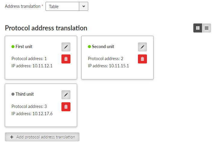
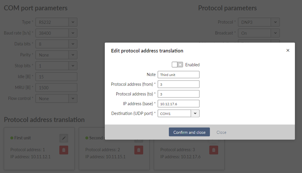
Note You may add a note to each address with your comments (UTF8 is supported) for your convenience.
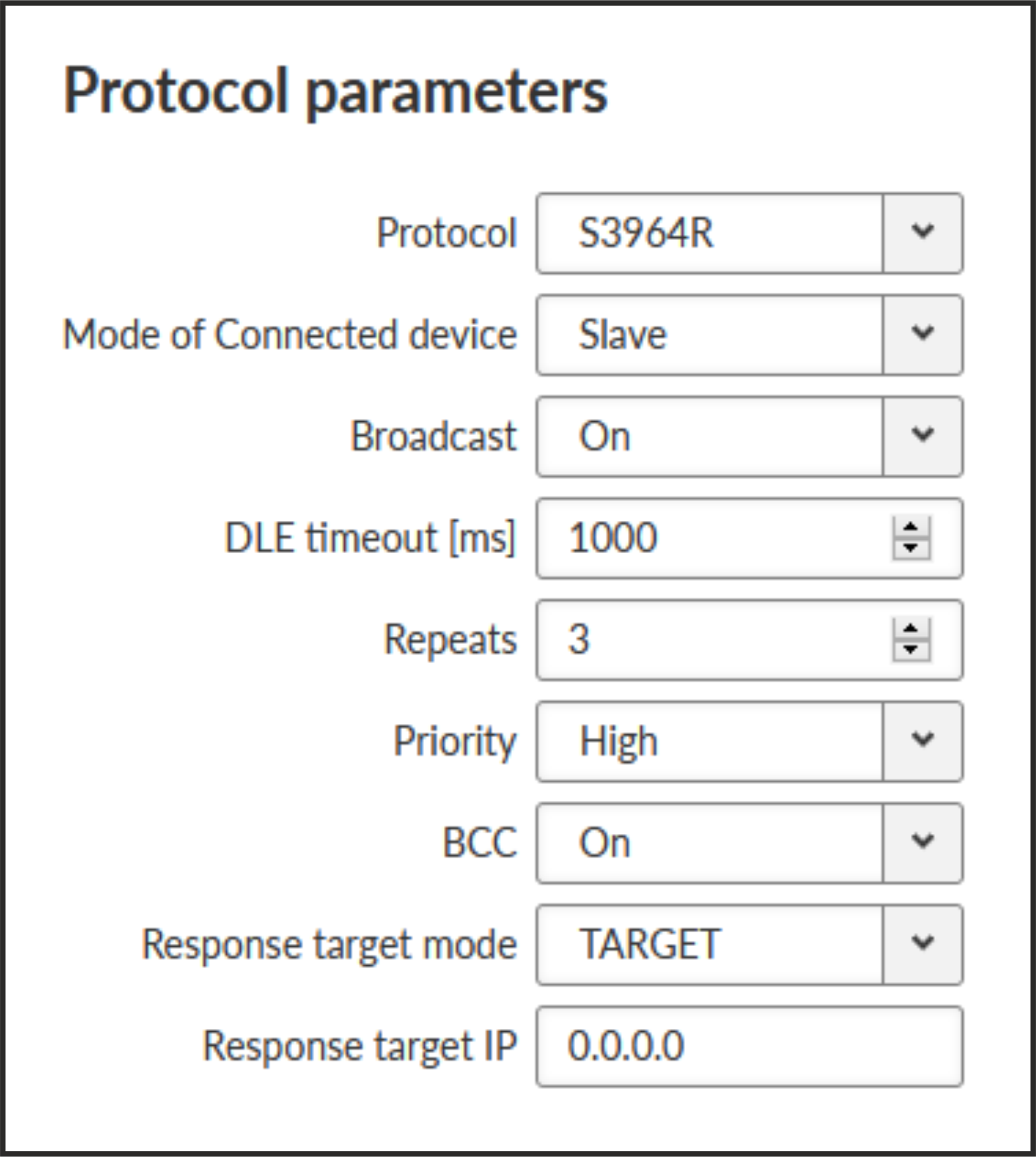
Some of the SCADA protocols are able to setup additional Slave device response behavior.
- Response target mode
List box {LASTRCV; TARGET}, default = “LASTRCV”
Response for the incoming frame shall be directed to the IP address of the Master which sent the frame (LASTRCV) or to a specified IP address (TARGET).
- Response target IP
IP address to which the response is sent when TARGET is chosen in the Response target mode.
The None protocol switches the COM port off. All incoming data will be thrown away, no data will be sent into the COM interface.
Async link creates an asynchronous link between two COM ports on different M!DGE3 units. Received frames from COM port or from a Terminal server are sent without any processing transparently via router to the set IP destination and UDP port. Received frames from the network are sent to COM or Terminal server according to Destination (UDP port) parameter.
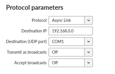
- Destination IP
Defines destination IP address of M!DGE3.
COMLI is a serial polling-type communication protocol used by Master-Slave application. Within one M!DGE3 network more COMLI Masters can be employed and one Slave can be polled by more Masters. Broadcast packets are not used.
The frame of COMLI protocol is sent transparently, but without STX, ETX and BCC. STX (start of data), ETX (end of data) and BCC (8-bit XOR) are added on the receiving participant. While transfer, data integrity is properly secured by individual protocol checksums.
| Note | |
|---|---|
The COMLI protocol in the M!DGE3 is not fully compatible on COM port with RipEX and MR modems. M!DGE3 implementation is not supporting “Intercharacter tx delay”. |
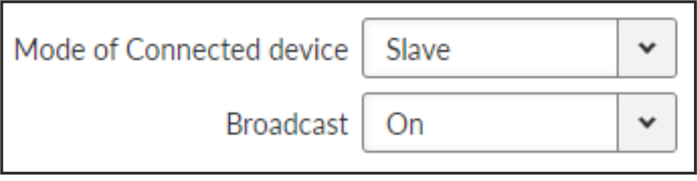
- Mode of Connected device: MASTER
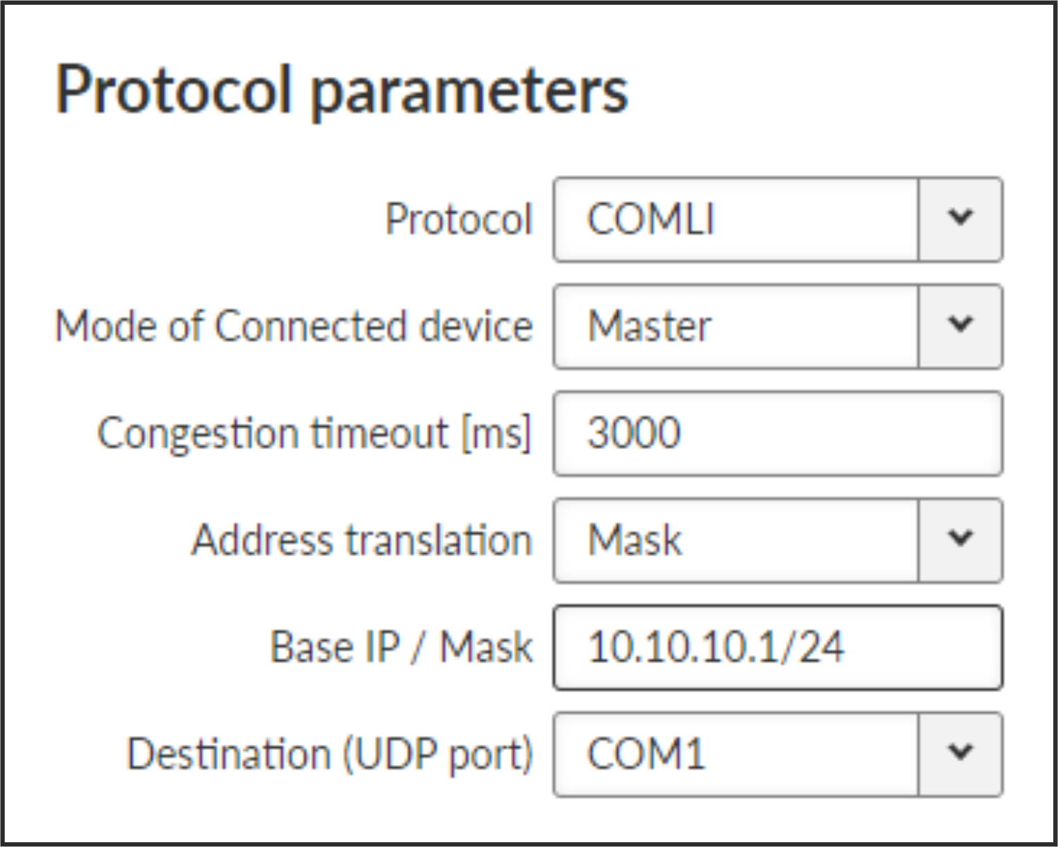
- Congestion timeout [ms]
Number {0 – 65535}, default = 3000, 0 switches this functionality off
Timeout for checking of the duplicity of two following frames. Used when the very same frame is incoming via COM port within the timeout measured from the moment of dispatch of the previous frame.
- Mode of Connected device: SLAVE
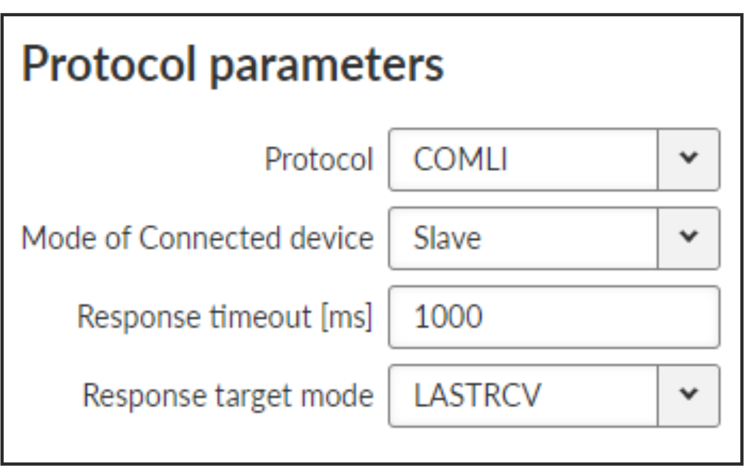
- Response timeout [ms]
Number {0 – 16383}, default = 1000
COMLI protocol response timeout is used for waiting on COM port for the response of connected device.
- Response target mode
List box {LASTRCV; TARGET}, default = ”LASTRCV”
Slave response will be sent to the address of the last received request (LASTRCV) or to the specified Response target IP address (TARGET).
Each frame in the DNP3 protocol contains the source and destination addresses in its header, so there is no difference between Master and Slave in terms of the M!DGE3 configuration. The DNP3 allows both Master-Slave polling as well as report-by-exception communication from the remote units.
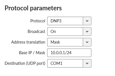
The common parameters (e.g. address translation) shall be set.
Each frame in the Allen-Bradley DF1 protocol contains the source and destination addresses in its header, so there is no difference between Master and Slave in the Full duplex mode in terms of M!DGE3 configuration.
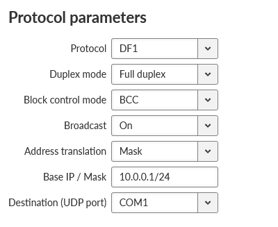
- Duplex mode
List box {Full duplex; Half duplex}, default = “Full duplex“
Mode of DF1 protocol operation: Only Full duplex mode is implemented now.
DF1 advanced parameters
Protocol DF1 supports protocol local acknowledgment. Typically the default setting shall be used. In case a need it is possible to change ACK parameters in ADVANCED > Generic > com_x_prot/Protocol_DF1 menu.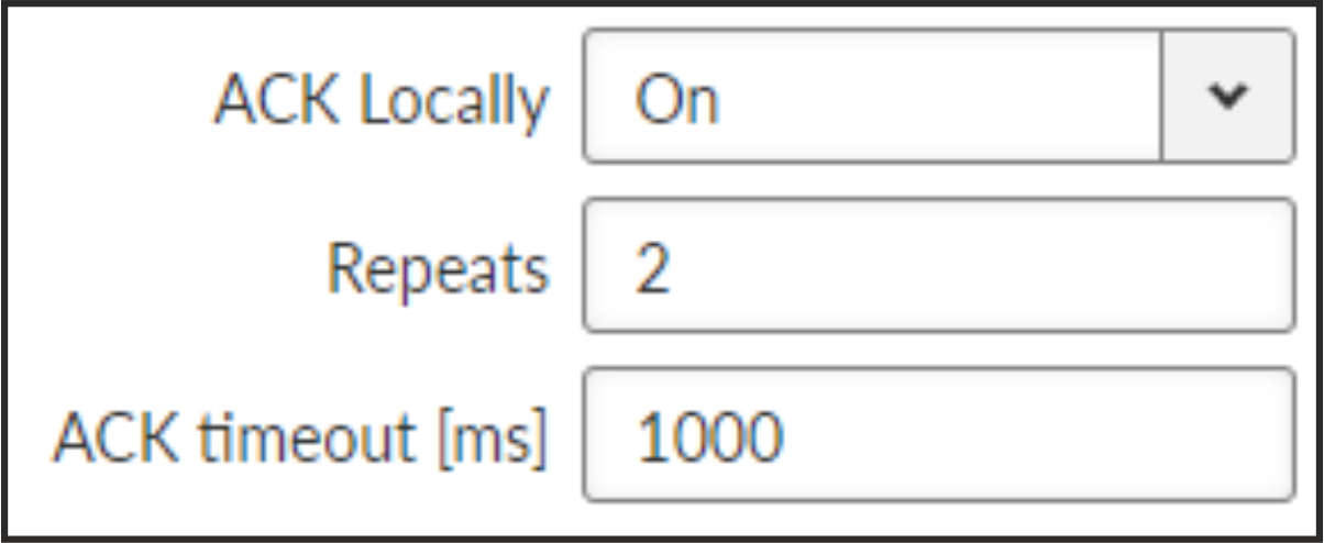
- ACK locally
List box {On; Off}, default = ”On”
Allows to switch On / Of the local ACK
- Repeats
Number {0 – 31}, default = 2
Sets number of repeats when local ACK is nor received.
- ACK timeout [ms]
Number {0 – 1683}, default = 1000
Timeout of waiting for ACK.
- Block control mode
List box {BCC; CRC}, default = “BCC”
According to the DF1 specification, either BCC or CRC for Block control mode (data integrity) can be used.
Note According to the DF1 specification, packets for the destination address 0xFF are considered broadcasts. Hence when Broadcast is On, packets with this destination are handled as broadcasts.
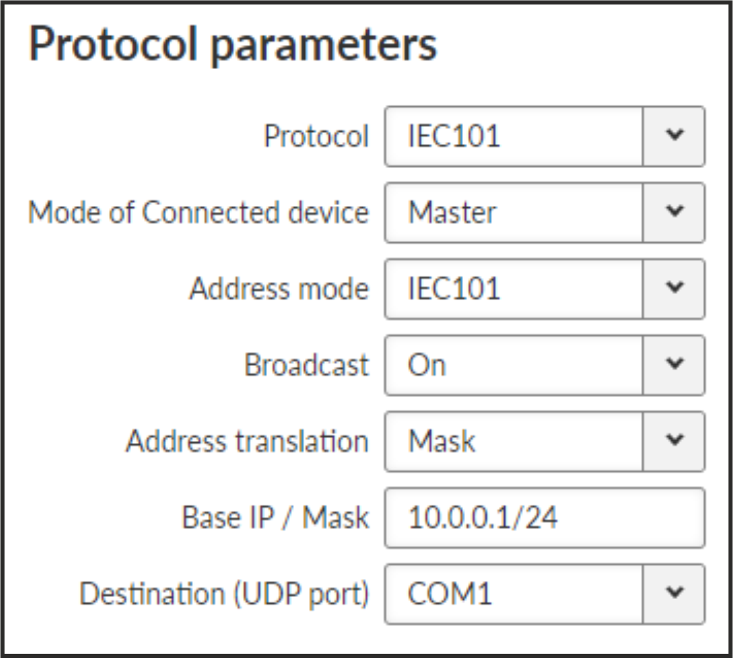
- Mode of Connected device
List box {Master; Slave; Combined}, default = “Master”
Note For connected SCADA Master set Master, for connected SCADA Slave set Slave.
- Address mode
List box {IEC101; 2B ADDR; TELEGYR; SINAUT; No addr}, default = “IEC101”
MARS-A is a full duplex protocol featuring:
– 32bit long addresses
– error detection (based on 16 bit checksum (XOR) or 16 bit CRC)
– error correction
MARS-A was widely used by legacy radio modems in the MORSE system from the year 1999.
The new implementation of this protocol in M!DGE3 or M!DGE3 is limited to the parts of the complex protocol which can be used together with modern packet type of these routers:
USER DATA (0x09) from router to the serial interface (e.g. to RTU),
USER DATA (0x09) and PROT DATA (0x0A) from serial interface (e.g. from RTU) to the router.
Mars-A headers are removed from the packet prior to transmitting to the network – only data are transmitted.
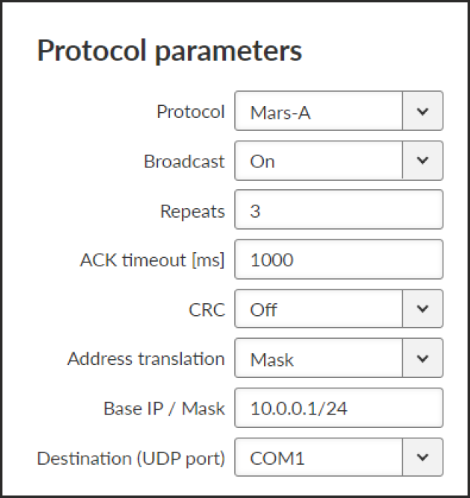
- ACK timeout [ms]
Number {0 – 16383}, default = 1000
Serial interface acknowledge timeout.
- Repeats
Number {0 – 31}, default = 3
Number of repeats. Repetition is triggered when NAK frame is received or if ACK frame was not received within ACK timeout.
- Security bit
List box {On; Off}, default = “Off”
Needed for compatibility with legacy MORSE network implementations. This parameter does not change protocol behavior.
- CRC
List box {On; Off}, default = “Off”
Error detection algorithm:
On – CRC algorithm is used
Off – XOR algorithm is used
Modbus RTU is a serial polling-type communication protocol used by Master-Slave application.
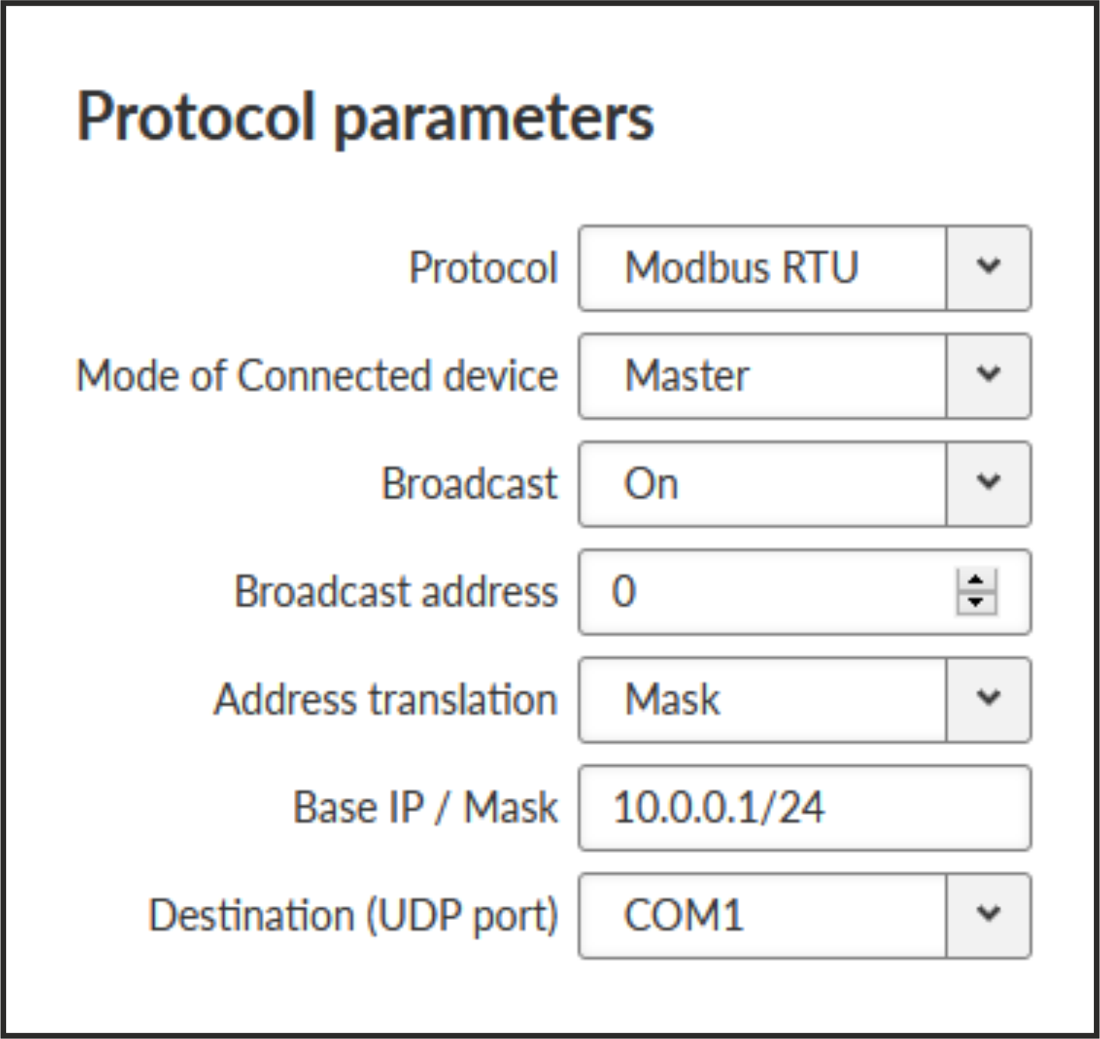
- Mode of Connected device
List box {Master; Slave}, default = “Master”
- Mode of connected device: MASTER
- Mode of connected device: SLAVE
- Response timeout
Number { 0 – 8190}, default = 300
The Response timeout parameter controls how long the unit waits for an acknowledgement frame. The timeout is started when the original frame received from the Cellular channel is transmitted to the connected device (over the serial channel). Transmission of any other frame to the connected device is temporarily blocked, whilst Response timeout is active. Response timeout = 0 disables this feature.
The PPP protocol (Point-to-Point Protocol, specified in RFC 1661) is intended for a direct duplex connection between two network points. It works at the link layer as an extension of the HDLC protocol. Both network points receive a configuration on the basis of which they negotiate connection properties with each other over the serial line. The consequence of a successful negotiation is the creation of network interfaces on both sides. Depending on the selected network protocol, these can be interfaces of different types. In our case, the IPCP protocol (IPV6CP) is used and the resulting interface is of the TUN type (e.g. ppp1). The interface is assigned an IP address according to the configuration and user data are transferred through it. PPP encapsulation is used to encapsulate IP packets into frames transmitted over a serial line (see Frame format, RFC 1662).
- Line Parameter Negotiation (LCP)
Basic connection parameters at the serial line level
LCP (Link Control Protocol, RFC 1661)
Negotiated parameters:
Maximum receive unit (MRU)
Asynchronous Control Character Map (ACCM)
Authentication protocol
Compression of the protocol field in the PPP frame header
Compression of the address and control fields in the PPP frame header
- Authentication
Optional, if negotiated, the appropriate protocol will be used
It can be two-sided, where each side may require a different protocol
Protocols:
PAP (Password authentication protocol)
CHAP (Challenge Handshake Authentication Protocol)
- Negotiation of data compression parameters (CCP)
Data compression type and parameters
Compression Control Protocol (CCP, RFC 1962)
- Network Protocol (NCP) Negotiation
Connection parameters at the network layer level
Network Control Protocol (NCP):
IPCP (Internet Protocol Control Protocol, RFC 1332)
IPv6CP (IPv6 Control Protocol, RFC 5072)
The format of PPP frames (RFC 1661, RFC 1662) is based on the HDLC protocol standard.
| Flag | Address | Control | Protocol | Information | Padding | FCS | Flag |
| 0x7E | 0xFF | 0x03 | 8/16 bits | * | * | 16/32 bits | 0x7E |
Flag: value 0x7E defined in the protocol specification
Address field: address field, value 0xFF defined in the protocol specification
Control field: control field, value 0x03 defined in the protocol specification
Protocol field: protocol field, indicates the type of data in the Information field
Example: 0xC021 for LCP, 0xC023 for PAP
Information: encapsulated data
Example: IP packet
Padding
Frame Check Sequence (FCS) field: control sequence for detecting transmission errors
Some configuration items are closely related to the native parameters of the pppd daemon. Individual parameters are listed in the text below in bullet points marked “pppd:” and detailed information about them can be found in the daemon’s manual pages.
“<NR>” is used to indicate the PPP index (1/2/3).
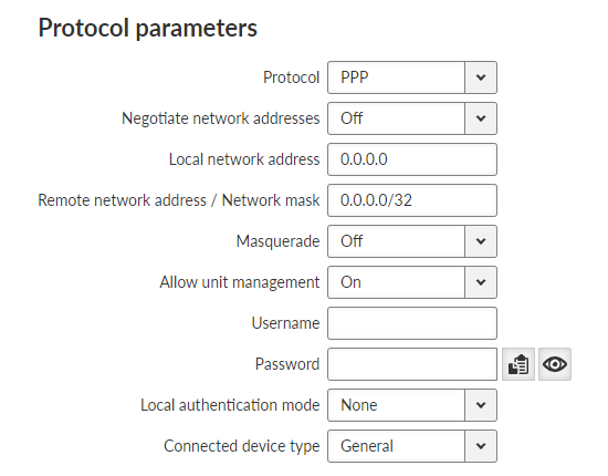
- Negotiate network addresses
List box {On; Off}, default = ”Off”
Enables local/remote PPP interface address negotiation.
If disabled Local network address and Remote network address must be set manually.
- Local network address
IP address; default = 0.0.0.0
Local IP address of the PPP interface
- Remote network address / Network mask
IP address; default = 0.0.0.0/32
Remote IP address and mask of the PPP interface. Address and Mask are used to determine the target range of a rule routing to the PPP interface
- Masquerade
List box {On; Off}, default = ”Off”
Enables/disables Source NAT (masquerade) on packets sent over the PPP interface.
With masquerade enabled, packets leaving the station over the PPP interface are rewritten with the source address to the address assigned to that interface
- Allow unit management
List box {On; Off}, default = ”On”
Enables unit management access via PPP interface
- Username
String {up to 50 char}, default = <empty>
The username to use when authenticating to the counterparty, regardless of the protocol that is required.
Printable ASCII characters are allowed, with the exception of the prohibited “, `, \, $, ;
- Passphrase
String {up to 50 char}, default = <empty>
The passphrase to use when authenticating to the counterparty, regardless of the protocol that is required.
Printable ASCII characters are allowed, with the exception of the prohibited “, `, \, $, ;
- Local authentication mode
Selection of the protocol with which the counterparty is to be authenticated when establishing a connection.
For PAP (legacy) and CHAP options, the credentials set by Local authentication username and Local authentication password are used
- Local authentication username
String {up to 50 char}, default = <empty>
The username that the counterparty should use during authentication (see Local authentication mode).
Printable ASCII characters are allowed, with the exception of the prohibited “, `, \, $, ;
- Local authentication password
String {up to 50 char}, default = <empty>
The password that the counterparty should use during authentication (see Local authentication mode).
Printable ASCII characters are allowed, with the exception of the prohibited “, `, \, $, ;
- Connected device type
List box {General; TETRA terminal (Motorola MTM5x00)}, default = ”General”
Connected device type. Sets the corresponding command sequence to switch the connected device to PPP mode.
Negotiate network addresses must be enabled for TETRA.
Advanced menu parameters:
- Asynchronous control character map
Number {0 – 65535}, default = 0
Async-Control-Character-Map (ACCM) settings.
A non-zero value can be used to select control characters that the counterparty should not include in sent PPP packets.
- LCP keepalive failure count
Number {0 – 255}, default = 0
A non-zero value means the maximum number of sent LCP echo-request messages before the peer is marked as disconnected and the connection is closed (see LCP keepalive interval [s]).
A zero value disables the function.
- LCP keepalive interval [s]
Number {0 – 255}, default = 10
Interval of sending LCP echo-request messages, to which the counterparty responds with an LCP echo-reply message in normal state.
Along with that entry LCP keepalive failure count can be used to detect if a party is connected
Active if LCP keepalive failure count is greater than 0
- Idle timeout to reconnect [s]
Number {0 – 65535}, default = 0
Disconnects an inactive connection after a defined period of time
- Enable using modem control lines
List box {On; Off}, default = ”Off”
Option to use “modem control lines” (DTR/DSR serial port signals).
- Enable control messages logging
List box {On; Off}, default = ”Off”
Option to verbose pppd daemon control messages.
Messages are written to the standard log /var/log/pppd_<NR>/log, which is available in a Diagnostic package.
- Compression negotiation mode
List box {Automatic; Manual}, default = ”Automatic”
Mode for selecting configuration parameters related to compression (all remaining items below). When Automatic is selected, the configuration items below are ignored and the pppd daemon uses its default values. When Manual is selected, the configuration items below are active and their values are used by the pppd daemon when negotiating with the counterparty.
- Enable address and control field compression
List box {On; Off}, default = ”On”
Choice of whether to negotiate address and control field compression in the PPP frame header (Address/Control field compression, see Frame format), in both directions of data transfer.
Active if Compression negotiation mode is Manual.
- Enable protocol field compression
List box {On; Off}, default = ”On”
Choice of whether to negotiate protocol field compression in the PPP frame header (Protocol field compression, see Frame format), in both directions of data transfer.
Active if Compression negotiation mode is Manual.
- Van Jacobson IP header compression max slots
Number {0; 2 – 16}, default = 16
Option of Van Jacobson compression of IP headers.
A non-zero value is a parameter of the compression algorithm (number of connection slots).
A zero value disables the function.
Active if Compression negotiation mode is Manual.
- Enable compression control protocol
List box {On; Off}, default = ”On”
Option to use CCP (Compression Control Protocol) to negotiate data compression parameters.
The option to disable CCP is provided for compatibility with legacy PPP clients that do not support data compression.
Active if Compression negotiation mode is Manual.
- BSD data compression receive code size
Number {0; 9 – 15}, default = 15
A non-zero value is a parameter of the “BSD-Compress” algorithm for data compression in the incoming direction.
A zero value disables the function.
Active if Compression negotiation mode is Manual and Enable compression control protocol is disabled.
- BSD data compression transmit code size
Number {0; 9 – 15}, default = 15
A non-zero value is a parameter of the “BSD-Compress” algorithm for data compression in the outgoing direction.
A zero value disables the function.
Active if Compression negotiation mode is Manual and Enable compression control protocol is disabled.
- Deflate data compression receive code size
Number {0; 9 – 15}, default = 15
A non-zero value is a parameter of the “Deflate” algorithm for data compression in the incoming direction.
A zero value disables the function.
Active if Compression negotiation mode is Manual and Enable compression control protocol is disabled.
- Deflate data compression transmit code size
Number {0; 9 – 15}, default = 15
A non-zero value is a parameter of the “Deflate” algorithm for data compression in the outgoing direction.
A zero value disables the function.
Active if Compression negotiation mode is Manual and Enable compression control protocol is disabled.
- Routing Mode
The listbox is extended with PPP <NR> options
If the routing rule has one of the PPP <NR> options selected, routing is done to the appropriate PPP interface.
- Routing Persistent
List box {On; Off}, default = ”Off”
The routing rule is persistent (see Cellular configuration for detailed explanation).
PPP status information is available in the Diagnostics > Information > Interfaces > PPP menu. Status provides following information
Interface
PPP Interface name.
State
Current state of the PPP interface daemon.
Peer MRU
Maximum receive unit (MRU) in bytes requested during negotiation by the counterparty.
Peer Auth. mode
Authentication protocol requested by counterparty.
Peer ACCM
ACCM setting requested by counterparty.
Negotiated compression options
Negotiated options of PPP compression.
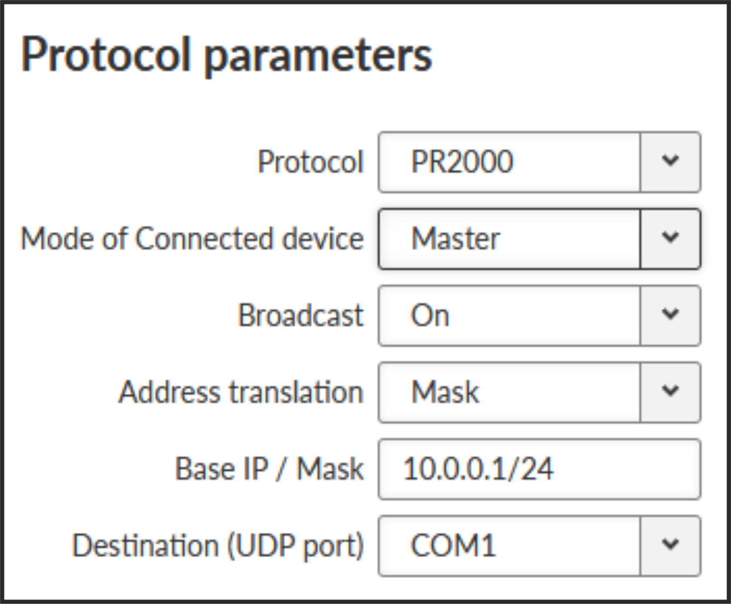
PR2000 is an abbreviation for the PROTEUS 2000 SCADA protocol. This protocol is used in Master-Slave applications.
The PR2000 protocol is implemented in a fully transparent manner. The original protocol frames are transported over the network in their entirety.
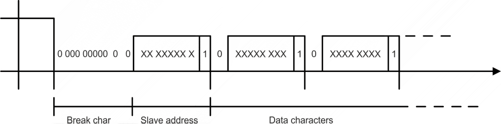
The 3964 protocol is utilized by the Siemens Company as a Point-to-Point connection between two controllers. Meanwhile it has developed into an industry standard that can be found on many devices as a universal communications interface. 3964R is the same as 3964, in addition it only uses BCC (Block Check Character). 3964(R) handles only the link layer (L2 in OSI model), hence M!DGE3 uses a similar way to read “SCADA address” as in UNI protocol.
There is a handshake STX(0x02) – DLE(Ox10) on the start of communication and DLE+ETX – DLE on the end. This handshake is performed by M!DGE3 locally, it is not transferred over the M!DGE3 network.
Communication goes as follows:
LocalRTU −> STX −>
Local M!DGE3
LocalRipEX −> DLE −>
LocalRTU
LocalRTU −> DATA+DLE+ETX+BCC −> Local M!DGE3
LocalRipEX −> DATA −> Remote M!DGE3*
Local M!DGE3 −> DLE −>
LocalRTU
Remote M!DGE3 −> STX −> RemoteRTU
RemoteRTU −> DLE −>
Remote M!DGE3
Remote M!DGE3 −> DATA+DLE+ETX+BCC −>
RemoteRTU
RemoteRTU −> DLE −> RemoteRipEX
* only this packet is transferred over the M!DGE3 network, all the other ones are handled locally.
- Master
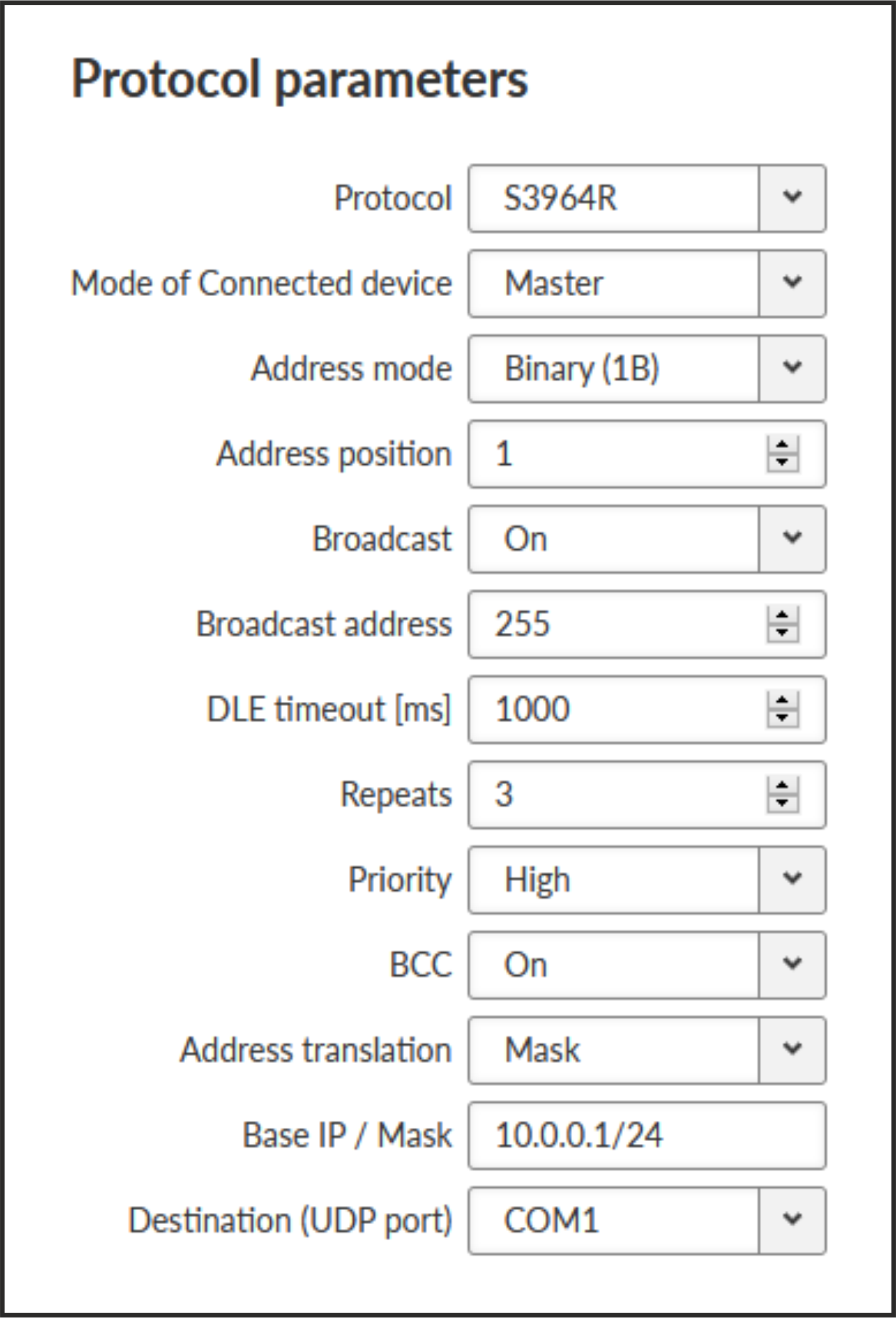
- Address mode
List box {Binary (1 B); Binary (2B LSB first); Binary (2B MSB first)}, default = “Binary (1 B)”
M!DGE3 reads the Protocol address in the format and length set (in Bytes).
- Address position
Specify the sequence number of the byte, where the Protocol address starts.
Note 3964(R) protocol is using escape sequence (control sequence) for DLE(0x10). I.e. when 0x10 is in user data, 0x1010 is sent instead. When address position is calculated, the bytes added by escape sequence algorithm are not taken into account.
Note The first byte in the packet has the sequence number 1, not 0.
- Slave
- DLE timeout [ms]
Number {300 – 8190}, default = 1000
M!DGE3 expects a response (DLE) from the connected device (RTU) within the set timeout. If it is not received, M!DGE3 repeats the frame according to the “Retries” setting.
- Retries [No]
Number {0 – 7}, default = 3
When DLE packet is not received from the connected device (RTU) within the set DLE timeout, M!DGE3 retransmits the frame. The number of possible retries is specified.
- Priority
List box {Low; High}, default = “Low”
When the equipment sends STX and receives STX instead of DLE, there is a collision, both equipments want to start communication. In such a case, one unit has to have a priority. If the Priority is High, M!DGE3 waits for DLE. When it is Low, M!DGE3 sends DLE.
Note Obviously, two pieces of equipment which are communicating together must be set so that one has High priority and the other has Low.
- BCC
List box {On; Off}, default = “On”
BCC (Block Check Character) is a control byte used for data integrity control, it makes the reliability higher. BCC is used by 3964R, 3964 does not use it.
M!DGE3 checks (calculates itself) this byte while receiving a packet on COM. M!DGE3 transmits DLE (accepts the frame) only when the check result is OK. BCC byte is not transferred over the M!DGE3 network, it is calculated locally in the end M!DGE3 and appended to the received data.
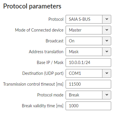
SAIA S-Bus protocol was widely used by legacy radio modems in the MORSE system. The S-Bus protocol is implemented as an access module for communication with the SAIA PCD device. The protocol is a MASTER/SLAVE type; the MASTER does not have its own address. There can be at most 254 SLAVEs, the address 255 is reserved for broadcast transmitting which is not acknowledged. The physical layer of the S-Bus protocol uses the RS232 or RS485 interface. The broadcast address 255 is not supported for M!DGE3.
Protocol frame has to be as whole received in the one buffer, so the IDLE parameter should be set properly. The S-bus protocol header does not always contain the length of the data, so it is not possible to work with fragmented and defragmented frames.
- Mode of connected device
List box {Master; Slave; Slave Plus}, default= “Master”
Master and Slave behaves like standard Master or Slave Saia PCD. The Slave Plus mode allows to behave in limited way as a Master and sends to other Slave/Slave Plus write command (read command is not allowed).
- Protocol mode
List box {Break; Data}, default =”Break”
Break or Data protocol modes can be used.
- Break mode (SM0)
The frames are synchronised by the break characters of a configured length which are sent before the addressed command.
Break mode is available only with COM port, it is not implemented on TS (the break signal is not available there). The Break signal check is very rough (with step of 100 ms) due to Linux kernel limitations.
- Data mode (SM2)
Frame synchronization is accomplished by inserting the character 0xB5 in the beginning of frame. If another character 0xB5 should appear in the frame, then it is replaced by the following DLE sequence:
Character DLE sequence 0x85 0xC500 0xC5 0xC501 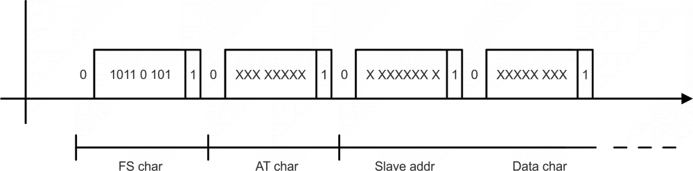
Note See details of the ’s implementation on https://www.racom.eu/eng/support/prot/sbus/index.html
- Mode of Connected device: MASTER
Transmission control timeout [ms]
Number {0 – 65535}, default = 11500Master timeout. This timeout is reset after receiving of an answer from Slave or a frame incoming from the connected master.
- Mode of Connected device: SLAVE
Response timeout [ms] Number {0 – 16383}, default = 300
Slave’s response timeout – waiting for response, otherwise the reply to master is resent.
- Repeats
Number {0 – 7}, default = 3
Number of repeats when the response from master is not received.
- Break mode
(additional parameter)
Master, Slave Plus
Break validity time [ms]
Number {0 – 5000}, default = 1000Slave, Slave Plus
Break length [ms]
Number {0 – 128}, default = 2Length of break in ms.
RDS protocol is a protocol used in MRxx networks.
It supports network communication; any node in the network can talk to any
other (unlike Master-Slave type of protocols). The RDS protocol
is typically used when combining RipEX and MRxx networks or SCADA networks
adapted to MRxx networks.
Frames are received from the Cellular channel and sent to
COM1-3 or Terminal server 1-5 according to UDP port settings and vice versa – from wire
to Cellular
channel.
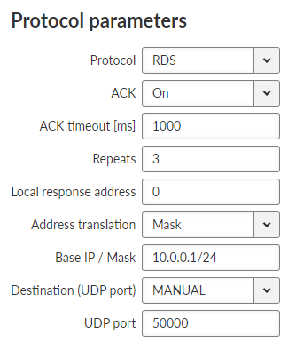
- ACK
List box {On; Off}, default = “On”
Frame acknowledgement when transmitted over wire (COM or Ethernet) interface. ACK (0x06) frames are transmitted on successful reception and NAK (0x15) on unsuccessful frame reception.
- ACK timeout [ms]
Number {0 – 16383}, default = 1000
Note ACK timeout is measured from the beginning of the packet transmission.
When “ACK” is enabled, M!DGE3 is waiting “ACK timeout [ms]” after transmitting frame to receive acknowledgement. If the ACK frame isn’t received, the frame is re-transmitted. Frame re-transmission happens up to “Repeats” number of times.
- Repeats
Number {0 – 31}, default = 3
Number of frame re-transmissions.
- Local response address
Number {0 – 255}, default = 0
This address is used only with status query (0x51). Response of M!DGE3 is “0x54 <Local response address> 0x00”.
UNI is the ‘Universal’ protocol utility designed for M!DGE3. It is supposed to be used when the required application protocol is not available in M!DGE3 and the network communication is using addressed mode (which is a typical scenario). The key prerequisite is: messages generated by the Master application device must always contain the respective Slave address and the address position, relative to the beginning of the message (packet, frame), is always the same (Address position). Generally, two communication modes are typical for UNI protocol: In the first one, communication is always initiated by the Master and only one response to a request is supported; in the second mode, Master-Master communication or combination of UNI protocol with ASYNC LINK protocol and spontaneous packets generation on remote sites are possible.
The UNI protocol is fully transparent, i.e. all messages are transported and delivered without any modifications.
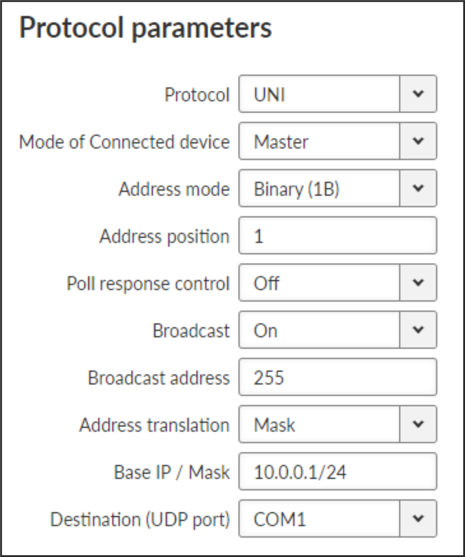
- Mode of Connected device
List box: {Master, Slave}, default = Master
- Adress mode
List box {Binary (1B); ASCII (2B); Binary (2B LSB first); Binary (2B MSB first)}, default = “Binary (1B)”
Protocol address format and length (in Bytes). ASCII 2-Byte format is read as 2-character hexadecimal representation of one-byte value. E.g. ASCII characters AB are read as 0xAB hex (10101011 binary, 171 decimal) value (the ASCII-2-Byte format function will be available in a future FW release).
- Address position
Number {1 – 255}, default = 1
Specify the sequence number of the byte, where the Protocol address starts. Note that the first byte in the packet has the sequence number 1, not 0.
- Poll response control
List box {On; Off}, default = “On”
“On” – The Master accepts only one response per a request and it must come from the specific remote to which the request has been sent. All other packets are discarded. This applies to the Master – Slave communication scheme.
Note It may happen, that a response from a slave (No.1) is delivered after the respective timeout expired and the Master generates the request for the next slave (No.2) in the meantime. In such case the delayed response from No.1 would have been considered as the response from No.2. When Poll response control is On, the delayed response from the slave No.1 is discarded and the Master stays ready for the response from No.2.
“Off” – The Master does not check packets incoming from the RF channel – all packets are passed to the application, including broadcasts. That allows e.g. spontaneous packets to be generated at remote sites. This mode is suitable for Master-Master communication scheme or a combination of the UNI and ASYNC LINK protocols.
- Mode of Connected device: SLAVE
Generally, a Terminal Server (also referred to as a Serial Server) enables connection of devices with serial interface to a M!DGE3 over the local area network (LAN). It is a virtual substitute for devices used as serial-to-TCP (UDP) converters.
In some special cases, the Terminal server can be also used for reducing the network load from applications using TCP. A TCP session can be terminated locally at the Terminal server in M!DGE3, user data extracted from TCP messages and processed like it comes from a COM port. When data reaches the destination M!DGE3, it can be transferred to the RTU either via a serial interface or via TCP (UDP), using the Terminal server again.
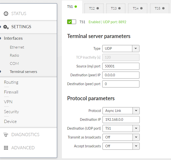
Up to 5 independent Terminal servers can be set up. Each one can be either TCP or UDP Type, TCP Inactivity is the timeout in seconds for which the TCP socket in M!DGE3 is kept active after the last data reception or transmission. As source IP address of a Terminal server will be used the IP address of the M!DGE3 ETH interface (Local preferred source address if exists see Section 7.2.1, “ Static”), Source (my) port can be set as required. Destination (peer) IP and Destination (peer) port values belong to the locally connected application (e.g. a virtual serial interface). In some cases, applications dynamically change the IP port with each datagram. In such a case set Destination port=0. M!DGE3 will then send replies to the port from which the last response was received. This feature allows to extend the number of simultaneously opened TCP connections between a M!DGE3 and locally connected application to any value up to 10 on each Terminal server. Protocol follows the same principles as a protocol on COM interface.
For details of settings see Section 7.1.2.2, “Common Protocol parameters”.
| Note | |
|---|---|
Max. user data length in a single datagram processed by the Terminal server is 8192 bytes. |
| Note | |
|---|---|
The port ranges 0-1023 and 8800-9823 are reserved and prohibited for Terminal Server. Port 502 is an exception for ModbusTCP. |
M!DGE3 can have up to two Cellular modules (MAIN and optional EXT). All features are identical for both. If both modules are used, each SIM card has to be assigned to a specific module.
APN must always be set up, all other parameters can keep their default values.
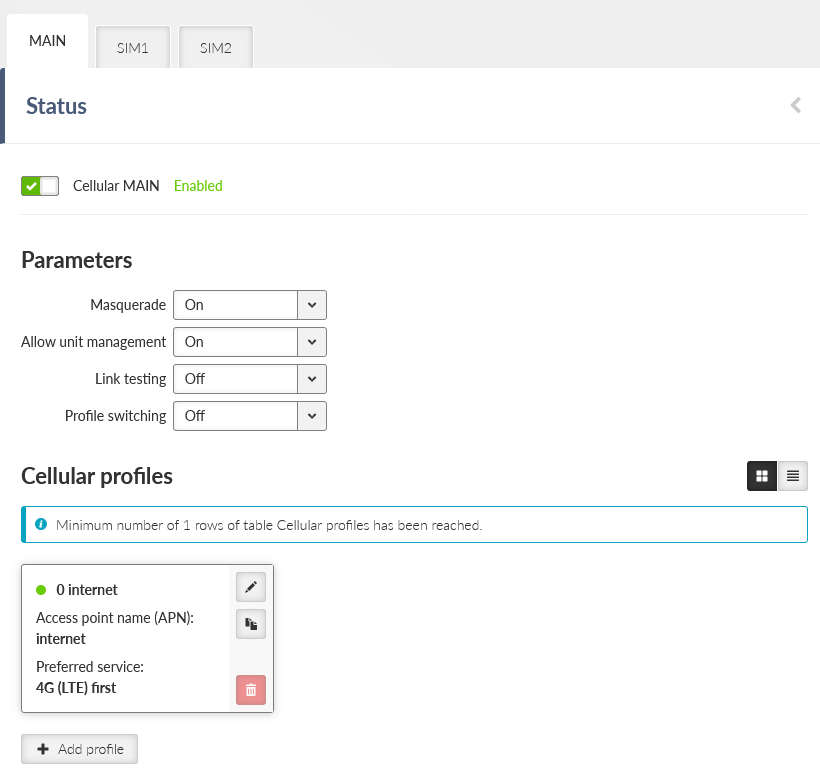
- Enable / Disable cellular MAIN/EXT:
Enables / Disables the cellular MAIN/EXT. When disabled (default), the module power is off.
| Note | |
|---|---|
Routing Mode “WWAN MAIN/EXT” is added to the Static routing rules definition. When this mode is selected, the routing Gateway parameter is ignored. The packet is forwarded to the Cellular (WWAN) interface instead. Routing rules are enabled / disabled automatically when the Cellular (WWAN) interface is opened / closed. No routing rules are added automatically after configuring a new cellular profile. Add all appropriate routing manually (e.g., default route 0.0.0.0/0 via WWAN interface). |
| Note | |
|---|---|
This section closely cooperates with Section 7.7.5, “SMS”. |
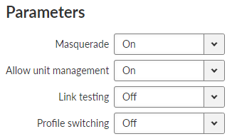
- Masquerade
List box {On; Off}, default = “On”
Enables / Disables SNAT (MASQUERADE) for the packets outgoing from the WWAN interface.
When on, the source address of packets outgoing via the Cellular WWAN interface will be changed to the address assigned to this interface (WWAN IP address is used instead of internal/LAN IP addresses). Returning packets will be correctly routed back to its original source (internal device).
- Allow unit management
List box {On; Off}, default = “On”
Allows to manage the unit over WWAN interface.
- Link testing
List box {On; Off}, default = “Off”
Enables / Disables Link testing.
- Profile Switching
List box {On; Off}, default = “Off”
Enables / Disables automatic Profile switching.
Set of defined profiles (at least one profile is required), which are setting parameters of requested service of the network (e.g APN).
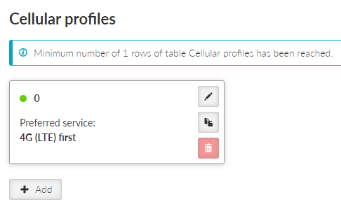
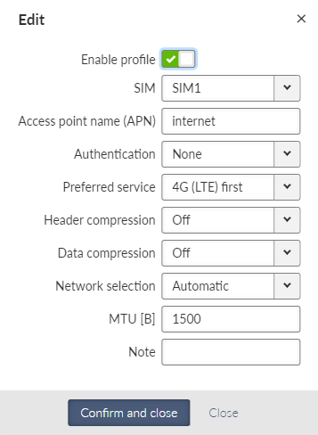
- Enable profile
Enables / Disables specific profile.
- Access point name (APN)
String {up to 99 char}, default = <empty>
The APN for access into the cellular network. Valid APN is provided by customers Cellular provider.
- Authentication
List box {None; PAP (legacy); CHAP}, default = “None”
Selects the method of authentication into the APN.
- None
No authentication is used for the APN access.
- PAP (legacy)
PAP (Password Authentication Protocol) authentication. We do not recommend to use this option because of security issues (the option is provided to offer legacy systems compatibility). Username and Password are required.
- CHAP
CHAP (Challenge-Handshake Authentication Protocol) authentication. Username and Password are required.
- Preferred service
List box {2G (GSM) first; 2G (GSM) only; 3G (UMTS) first; 3G (UMTS) only; 2G/3G (GSM/UMTS) only; 4G (LTE) first; 4G (LTE) only; 3G/4G (UMTS/LTE) only}, default = “4G (LTE) first”
Sets preferences and/or permission of the individual cellular network services.
Note Default value for cellular module ‘R’ and ‘S’ is set to Cat. M1. If the used service is different, you have to change it manually.
- Header compression
List box {On; Off}, default = “Off”
Enables / Disables the user data traffic IP headers compression. Not used with 4G service.
- Data compression
List box {On; Off}, default = “Off”
Enables / Disables the user data traffic data compression. Not used with 4G service.
- Network selection
List box {Automatic; Prefer manual; Lock to manual; Lock to home}, default = “Automatic”
Defines the network selection preferences:
- Automatic
Network is selected automatically.
- Prefer manual
The network according to the Location area identity (LAI) is preferred. Another network will be selected when the preferred network is not available.
- Lock to manual
Only the LAI filled in the Location area identity (LAI) parameter will be used.
- Lock to home
Only the home network will be used (if the SIM supports PLMN reading). This option can also be used as a “switch-off” for the roaming.
- Location area identity (LAI)
String {00000 – 999999}, default = 00000
The Public Land Mobile Network (PLMN) identification number of the cellular network.
This parameter occurs only, if parameter Network selection is set to “Prefer manual” or “Lock to manual”.
- MTU [B]
Number {70 – 1500}, default = 1430
Outgoing packets MTU. Default value matches to the value of the mPLS83W module and it is the most common value within cellular networks.
Minimum MTU value for IPv6 (Babel) = 1280 B.
- Note
Optional comment.
To enable continuous checking of the functional connection via the Cellular interface, Link testing can be activated. This service (Link testing) adds to the basic testing of the connection to the cellular network (Connection check) a test of the end-to-end connectivity through the entire network up to the specified target address(es). The test is carried out by sending an ICMP ping to the defined address(es) and waiting for a response.It is possible to test against one or two target addresses.

The test result is indicated by the link status:
START – initial status before the start of testing
RUNNING – the test succeeded, the link is considered to be OK, the test is performed with a Test period
SUSPECT – the test began to fail, the test is performed with a Repeat period
FAILED – the link is inoperative, the test is performed with a Repeat period
In a situation where the link is declared inoperative (test in FAILED status), the following actions are performed:
If Profile switching is disabled, a disconnection and re-login to the Cellular network is initiated.
If Profile switching is enabled, the switch to the next Profile is initiated.
Settings of Link testing for MAIN (EXT):
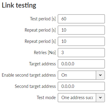
- Test period [s]
Number {3 – 3600}, default = 60
Time period, during which is the connection being tested.
- Repeat period [s]
Number {3 – 3600}, default = 10
If the test results as failed, the connection is tested again after defined time period.
- Retries [No]
Number {1 – 20}, default = 3
Amount of failed tests, after which is the link declared to be non-functional.
- Target address
IP address, default = 0.0.0.0
Primary tested IP address.
- Enable second target address
List box {On; Off}, default = “On”
Enables / Disables testing of the second IP address.
- Second target address
IP address, default = 0.0.0.0
Secondary tested IP address.
- Test mode
List box {One address succeeds; Both addresses succeeds}, default = “One address succeeds”
Defines the success of the test:
One address succeeds – only one address is enough to pass the test.
Both addresses succeeds – both addresses must pass the test.
| Note | |
|---|---|
If the connection to SIM card fails (missing SIM, wrong PIN), all profiles using that SIM will be blocked. If all profiles are blocked, the whole Cellular interface service will be blocked. |
In case of a malfunction of the current running profile, the module switches automatically to another (if it is defined). If the module has no more defined profiles to switch to, it switches back to the first one. After defined time period, the module can try to reconnect via the first profile again (independently on the profile queue). This section occurs only, if parameter Profile switching is set to “On”.
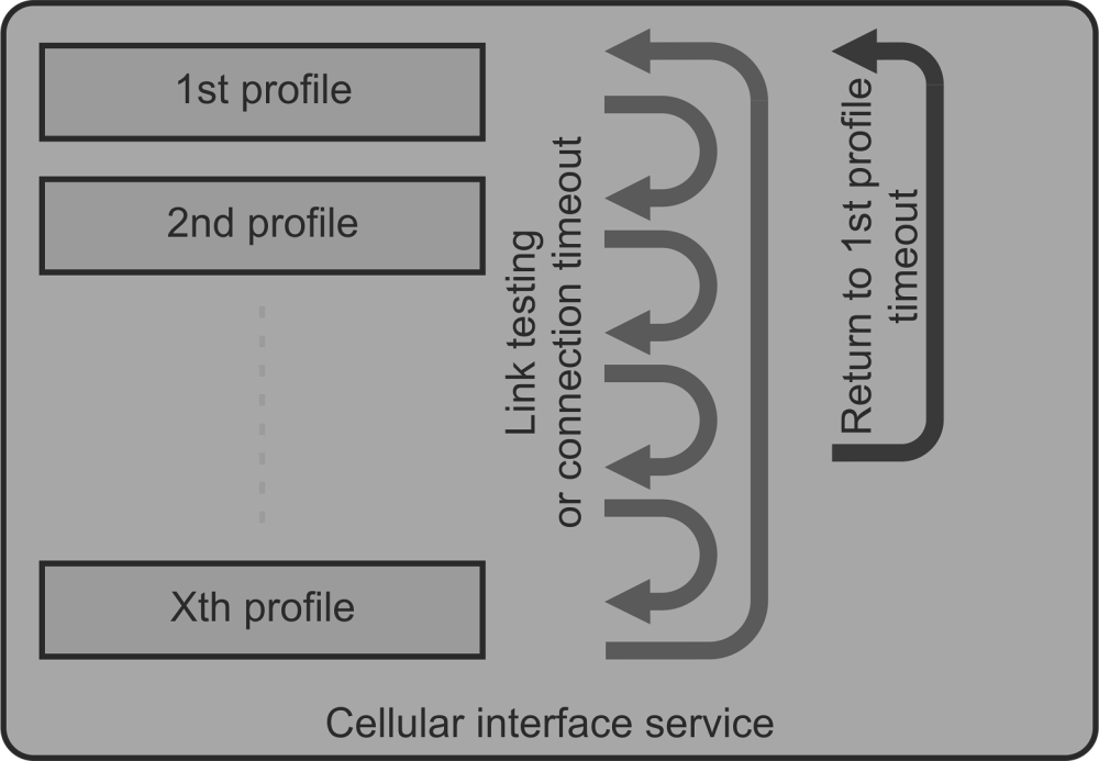
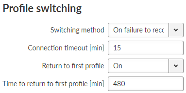
- Switching method
List box {On first failure; On failure to reconnect, On timeout}, default = “On first failure”
Defines the way of switching to the next profile, when the connection fails.
On first failure – after first failure, the module switches to another profile.
On failure to reconnect – after failure, the module tries to reconnect. If the reconnection is unsuccessful, the module switches to another profile.
On timeout – the module keeps reconnecting to its current profile for the time period of its timeout (parameter Connection timeout [min]).
- Connection timeout [min]
Number {3 – 60}, default = 15
Time period, during which is the module waiting for connection (after initial opening of the interface).
- Return to first profile
List box {On; Off}, default = “On”
When enabled, the module will switch back to its first profile after defined time period.
- Time to return to first profile [min]
Number {5 – 10080}, default = 480
Time period, after which is the current profile switched back to the first one.
SIM1 and SIM2 tabs contain the same setting for SIM1 and SIM2 respectively.
- PIN protection
List box {On; Off}, default = “Off”
Enables / Disables the SIM module PIN protection. It has to be switched on if the PIN is required. The parameter is ignored if the SIM does not require a PIN.
- PIN code
String {0000 – 9999}, default = “0000”
The PIN is used only when PIN protection is On and the module requires the PIN.
- Firewall L3
Parameters Input interface and Output interface can filter the traffic either coming to WWAN or leaving to WWAN (List box WWAN or EXT).
- NAT
SNAT – parameter Output interface can filter the traffic (List box WWAN or EXT).
Rules of SNAT (user settings) have higher priority than rules of MASQUERADE in this section (parameter Masquerade).
DNAT – parameter Input interface can filter the traffic (List box WWAN or EXT).
- IPsec
Automatic rules of MASQUERADE do not overwrite the source address of packets, which are encapsulated into IPsec.
It is recommended for IPsec to enable MOBIKE, if guided through Cellular.
Values are displayed from the moment of opening the SETTINGS menu. The values can be updated by using Refresh button.
Common status information and SIMs information are available.
Tab. 7.1: Signal levels for individual services
| Signal level | LED color | 2G: RSSI | 3G: RSCP | 4G: RSRP |
|---|---|---|---|---|
| Weak / No signal | Red | <= -95 dBm | <= -100 dBm | <= -100 dBm |
| Medium | Orange | -95 to -84 dBm | -100 to -89 dBm | -100 to -80 dBm |
| Good | Green | -84 dBm <= | -89 dBm <= | -80 dBm <= |
| Note | |
|---|---|
When using both antennas, the system measures the signal level on each antenna and uses the stronger signal. If ANT1 is disconnected, damaged, and ANT2 is connected, the menu (LED color) will display the signal level from ANT2, but transmission (Tx) communication will not be possible. Refer to sub-chapter 7.1.4.1.3 for link testing instructions. |
PPPoE (Point-to-Point Protocol over Ethernet) is a network protocol that encapsulates PPP frames within Ethernet frames. The PPP protocol itself is already described among serial protocols. With PPPoE, we distinguish between two basic phases: “Discovery” and “PPP Session”.
- Discovery phase
The primary goal of the PPPoE Discovery Phase is to acquire essential information for establishing the PPP Session Phase. This information includes the MAC address of the peer device and the PPPoE session ID.
- PPP Session phase
The primary goal of the PPP Session Phase is to establish and maintain a connection between the client and the server. This phase utilizes standard PPP frames for data exchange. All frames within this phase carry an ETHER_TYPE value of 0x8864 and are considered Ethernet unicasts.
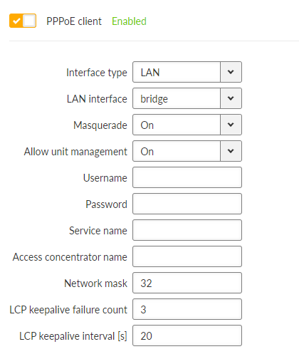
- Interface type
List box {LAN; VLAN}, default = “LAN”
This parameter specifies from which table the interface will be selected using a name.
LAN – The name of the LAN interface to be used for PPPoE connection establishment.
VLAN – The name of the VLAN interface to be used for PPPoE connection establishment.
- Masquarade
List box {On; Off}, default = “On”
Enables/disables SNAT (masquerade) on packets sent over the PPP interface.
With masquerade, outgoing packets from the station over the PPP interface have their source address rewritten to the address assigned to this interface. Returning packets are then correctly routed back through the station.
- Allow unit management
List box {On; Off}, default = “On”
Allows to manage the unit over PPP interface.
- Username
String {up to 64 characters}, default = <empty>
The username to be used for authentication with the peer, regardless of the protocol required.
- Passphrase
String {up to 64 characters}, default = <empty>
The passphrase to be used for authentication with the peer, regardless of the protocol required.
- Service name
String {up to 64 characters}, default = <empty>
The service name to be used when searching for the server to connect to.
- Access concentrator name
String {up to 64 characters}, default = <empty>
The name of the server to connect to.
- Network mask
Number {0 – 32}, default = 0
Used together with the peer’s IP address to determine the destination range of the routing rule pointing to the PPP interface.
- LCP keepalive failure count
Number {0 – 255}, default = 3 (disabled if 0)
A non-zero value specifies the maximum number of LCP request messages sent before the peer is considered disconnected and the connection is terminated.
- LCP keepalive interval
Number {0 – 255}, default = 10
The interval for sending LCP request messages, to which the peer normally responds with an LCP reply message.
This parameter can be used in conjunction with LCP keepalive failure count to detect whether the peer is connected.
This parameter is active only when LCP keepalive failure count is greater than 0.
M!DGE3 optionally provides cellular Wi-Fi interface using embedded Wi-Fi module. Wi-Fi interface can be used in Access point (AP) mode only. Client mode is not implemented.
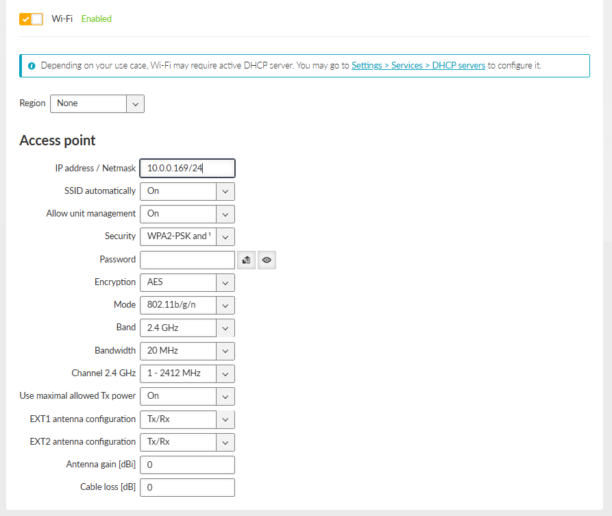
- Enable/Disable Wi-Fi
Check box {On; Off}, default = “Off”
Enables / Disables the Wi-Fi.
- Region
List box {ISO 3166-1 alpha-2 countries}, default = “None”
Setting the region in which the unit is operated. The purpose is to activate any regional restrictions on transmission power. These restrictions vary by region and by transmission band. The specific value of the maximum allowed EIRP in the selected region can be verified in the Status – the value “Maximum allowed EIRP [dBm]”.
- IP address / Netmask
IP address, default = “10.0.0.169”
Netmask {0-32}, default = “24”
Wi-Fi interface IP address, must not conflict with another address range.
- SSID automatically
List box {On; Off}, default = “On”
When automatic definition of SSID is enabled, the SSID contains unit Serial number.
- Hide SSID
List box {On; Off}, default = “Off”
Hides the SSID (network name) of a Wi-Fi AP
- Allow unit management
List box {On; Off}, default = “On”
Enables access to unit management through the Wi-Fi interface.
- Security
List box {Off, WPA-PSK (legacy), WPA2-PSK, WPA-PSK (legacy) and WPA2-PSK, WPA3-SAE, WPA2-PSK and WPA3-SAE}, default = “WPA2-PSK and WPA3-SAE”
Wi-Fi network security.
Note 802.1w (PMF) is enabled automatically with the mode set to any of “802.11a, 802.11b/g/n, 802.11a/n, 802.11a/n/ac” && security set to any of “WPA, WPA2, WPA3-SAE”. Otherwise, it is not enabled.
- Passphrase
String {up to 63 characters}, default = <empty>
Passphrase to connect to Wi-Fi Access Point.
- Encryption
List box {TKIP (legacy), AES (default), TKIP (legacy) and AES}, default = AES
Wi-Fi network encryption.
- Mode
List box {802.11a, 802.11b, 802.11b/g, 802.11b/g/n , 802.11a/n, 802.11a/n/ac}, default = 802.11b/g/n
IEEE 802.11 mode in which the Wi-Fi module will operate.
- Band
List box {2.4 GHz, 5 GHz}, default = 2.4 GHz
Band in which the Wi-Fi module will operate.
- Bandwitdh
List box {20 MHz ,40 MHz, 80 MHz}, default = 20 MHz
Wi-Fi network bandwidth.
- Channel 2.4 GHz
List box {Automatic, 1 – 2412 MHz, 2 – 2417 MHz, 3 – 2422 MHz, 4 – 2427 MHz, 5 – 2432 MHz, 6 – 2437 MHz, 7 – 2442 MHz, 8 – 2447 MHz, 9 – 2452 MHz, 10 – 2457 MHz, 11 – 2462 MHz, 12 – 2467 MHz, 13 – 2472 MHz, 14 – 2484 MHz}, default = “Automatic”
Select your 2.4 GHz Wi-Fi network channel. Includes ACS and automatic channel options, not only manual configuration. Available options depend on your Wi-Fi bandwidth settings.
- Channel 5 GHz
List box {Automatic, 36 – 5180 MHz, 40 – 5200 MHz, 44 – 5220 MHz, 48 – 5240 MHz, 52 – 5260 MHz, 56 – 5280 MHz, 60 – 5300 MHz, 64 – 5320 MHz, 100 – 5500 MHz, 104 – 5520 MHz, 108 – 5540 MHz, 112 – 5560 MHz, 116 – 5580 MHz, 120 – 5600 MHz, 124 – 5620 MHz, 128 – 5640 MHz, 132 – 5660 MHz, 136 – 5680 MHz, 140 – 5700 MHz, 144 – 5720 MHz, 149 – 5745 MHz, 153 – 5765 MHz, 157 – 5785 MHz, 161 – 5805 MHz, 165 – 5825 MHz}, default = “Automatic”
Select your 5 GHz Wi-Fi network channel. Includes ACS and automatic channel options, not only manual configuration. Available options depend on your Wi-Fi bandwidth settings.
Note Channels that require DFS cannot be used.
- Use maximal allowed Tx power
List box {On; Off}, default = “On”
Automatic selection of the transmitting power of the Wi-Fi module.
If the option is disabled:
- Maximal Tx power
Full number {0-16}, default = “16” [dBm]
Transmitting power of the Wi-Fi module.
- EXT1 antenna configuration
List box {Off, Tx, Rx, Tx/Rx}, default = “Tx/Rx”
Determines the functionality of the antenna connected to the Wi-Fi module via EXT1 port.
- EXT2 antenna configuration
List box {Off, Tx, Rx, Tx/Rx}, default = “Tx/Rx”
Determines the functionality of the antenna connected to the Wi-Fi module via EXT2 port.
- Antenna gain
Full number {0-30}, default = “0” [dBi]
Gain of the antenna connected to the Wi-Fi module.
Used in the calculation of the transmit power of the Wi-Fi module with a positive sign.
- Cable loss
Full number {0-30}, default = “0” [dB]
Used in the calculation of the transmit power of the Wi-Fi module with a negative sign.
The Access Control table allows you to control client access based on their MAC addresses.
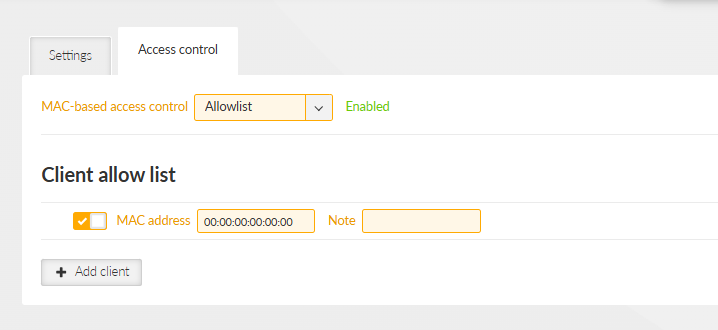
- MAC-based access control
List box {Off, Allowlist, Blocklist}, default = “Off”
Manage client access by MAC address.
- Allowlist
Alows only clients with MAC addresses in the list, others are blocked.
- Blocklist
Blocks clients with MAC addresses in the list, others are allowed
- Enable/Disable client
List box {On; Off}, default = “On”
Activates a rule for a given MAC address.
MAC address | MAC address , default = 00:00:00:00:00:00 MAC address of the client |
- DHCP server
It is possible to run a DHCP server over the Wi-Fi interface.
The DHCP server must be configured to allocate IP addresses from the address range specified by the configuration IP address / Netmask in the Wi-Fi interface.
- Events
Connection and disconnection of clients to the Wi-Fi AP is reported by events “Wi-Fi AP (EXT) reports client connected” and “Wi-Fi AP (EXT) reports client disconnected”
- Firewall L3
The firewall can filter traffic coming from the Wi-Fi interface by using the “EXT” option in the I/O interface settings.
- Hot standby
Wi-Fi is deactivated in passive mode and activated in active mode.
In passive mode, the module’s power supply is active, but the Wi-Fi interface is not active.
- Link manager
The Wi-Fi interface can be used in Link Manager as a WWAN (EXT) interface when configuring the link.
- NAT
SNAT and DNAT rules can modify traffic passing through the Wi-Fi interface by using the “EXT” option in the I/O interface settings.
The Wi-Fi interface name can be used when setting the manual I/O interface name (“Other”), but only if Wi-Fi (EXT) is active.
- Sleep mode
When sleep mode is active, it is possible to delay putting the device to sleep if user traffic is detected on the Wi-Fi interface.
M!DGE3 router supports both static and dynamic IP routing.
Static routing is based on fixed – static – definition of routing tables. Dynamic routing is based on automatic creating and updating of routing tables. Various methods and protocols are used for this purpose. Babel, OSPF and BGP standard routing protocols are available in M!DGE3 networks.
Link management option was added allowing to set the switchover of the main link (in the event of its failure) to an existing backup link by automatic changes of routing rules.
| Note | |
|---|---|
Due to static internal routing to clients, OpenVPN L3 is incompatible with dynamic routing protocols. Dynamic routing over the OpenVPN L3 interface will not function. |
| Note | |
|---|---|
M!DGE3e not supports Dynamic routing functionalities (Link management, Babel, OSPF, BGP). |
M!DGE3 works as a standard IP router with multiple independent interfaces: Network interfaces (bridging physical Ethernet interfaces), COM ports, Terminal servers, Cellular interface etc. Each of the interfaces has its own IP addresses and Masks. All IP packets are processed according to the Routing table.
Unlimited number of subnets can be defined on the Network interface. They are routed independently.
The COM ports are treated in the standard way as router devices, messages can be delivered to them as UDP datagrams to selected UDP port numbers. Destination IP address of COM port is IP of a Network interface (bridging Ethernet interfaces). The IP address source of outgoing packets from COM ports is equal to IP address of interface (Network interface) through which packet has been sent. The source address can also be assigned to Local preferred source address value – see description below. Outgoing interface is determined in Routing table according to the destination IP.
The IP addressing scheme can be chosen arbitrarily, only 127.0.0.0/8 and 192.0.2.233/30 and 192.0.2.228/30 restriction applies. It may happen that also the subsequent addresses from the 192.0.2.0/24 subnet according to RFC5737 may be reserved for internal usage in the future.
- Active
{On / Off}
Switches the rule on / off.
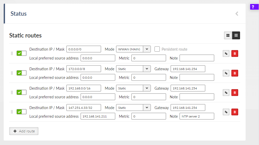
- Destination IP / mask
IP address, default = 0.0.0.0/0
Each IP packet, received by M!DGE3 through any interface (ETH, COM, …), has got a destination IP address. M!DGE3 (router) forwards the received packet either directly to the destination IP address or to the respective Gateway, according to the Routing table. Any Gateway has to be within the network defined by IP and Mask of one of the interfaces, otherwise the packet is discarded.
Each item in the routing table defines a Gateway (the route, the next hop) for the network (group of addresses) defined by Destination IP and Mask. When the Gateway for the respective destination IP address is not found in the Routing table, the packet is forwarded to the Default gateway, when Default gateway (0.0.0.0/0) is not defined, the packet is discarded.
The network (Destination IP and Mask) is written in CIDR format, e.g. 10.11.12.0/24.
Note Network defined by the same combination of Destination IP and Mask cannot be used for two different rules.
- Mode
List box {Static; WWAN (MAIN); WWAN (EXT); PPP1; PPP2; PPP3; Link manager; PPPoE Client}, default = Static
Static – Used for static IP routing rules.
WWAN (MAIN); WWAN (EXT) – Routing rule to the primary/secondary WWAN, which has a dynamically assigned address. The next hop will be directed through the “wwan” interface when it is open.
PPP1; PPP2; PPP3 – Routing rule to the PPP interface associated with the COM protocol. The interface may have a dynamically assigned address. Can only be set if the corresponding COM port is enabled and with the PPP protocol.
Link manager – Routing rule via active link selected by the Link manager. The rule will be dynamically switched in case of a link change or loss. It can be set if the Link manager is enabled.
PPPoE Client – Routing rule to the PPP interface created by the PPPoE client. The interface has a dynamically assigned address. It can only be set if the PPPoE client is active.
- Local preferred source address
IP address, default = 0.0.0.0
Local IP address used as a source address for packets originating in the local M!DGE3 unit being routed by this routing rule. It might be for example packets originating from the COM port or from the Terminal Server. If the address is set to 0.0.0.0 it is not considered active. The IP address has to belong to the Network interfaces.
- Metric
Number {0 – 4294967294}, default = 0
Routing rule metric value.
- Note
You may add a name to each route with your comments up to 16 characters (UTF8 is supported) for your convenience.
- Persistent route
List box {On; Off}, default = Off
Sets the persistence (time of presence) of dynamic routing rule.
This parameter is available only if parameter Mode is set to “WWAN (MAIN)” or “WWAN (EXT)”.
On – Routing rule is always present. When the WWAN interface is closed, it reports “unreachable” messages (via ICMP) and the traffic cannot be caught by a different rule.
Off – Routing rule exists only if the WWAN interface is open. If it is closed, the traffic can be caught by a different rule.
Table of loopback addresses contains IP addresses of M!DGE3, which are set on the loopback interface as “support” addresses independent on specific interface. Maximum number of addresses is 256. Loopback addresses can be useful e.g. for specific routing purposes or specific user data traffic. For example using different routing rules for different traffic.
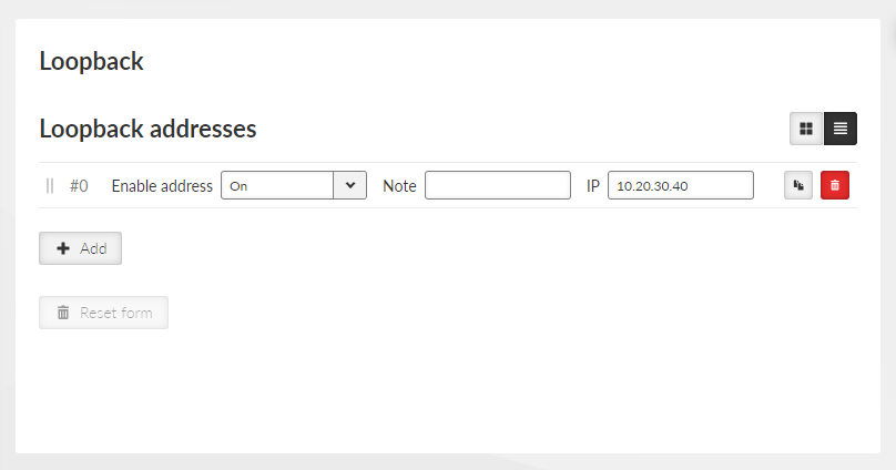
- Enable address
List box {On; Off}, default = “On”
- Note
Optional comment.
- IP
IP address, default = 0.0.0.0
Defines the IP address which will be set on the loop-back interface. The mask is automatically /32.
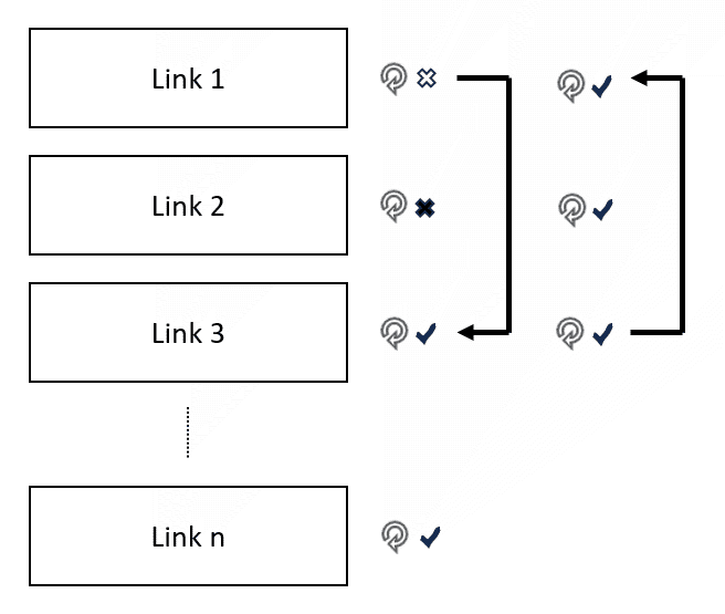
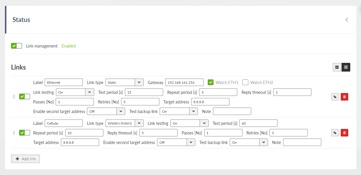
Link manager is a mechanism providing switching of several pre-configured alternative links (alternative routes). Link switch is triggered in case of the active link failure. Link failure can be detected passively – by checking link interface status (see Watched interface parameter) and actively by ICMP ping (see Link testing parameter).
Link testing is active on currently active link and all higher priority links (to detect when they are available again). Lower priority links can also be tested (see Test backup link parameter). When the current link fails, link manager switches to the next functional lower priority link. If the link is not being checked (Test backup link parameter is disabled), it is assumed to be functional. Routing rules are updated automatically on link switchover.
- Enable Link manager
Enables/disables the Link manager
- IPsec control
List box {Off; On}, default = “Off”
Enables / disables binding between a link and particular IPsec tunnel. This option is available only when IPsec is enabled and configured. Configuration parameter: SETTINGS > VPN > IPsec > IPsec associations > Management mode provides two options:
- Link manager (Master)
One of the IPsec associations is declared as Master. Traffic selectors (CHILD SA) define the traffic to be encrypted.
- Link manager (Slave)
All other associations are declared as Slave. No Traffic selectors are defined for such a tunnel. The Master’s traffic selectors are used.
Every alternative link is configured separately. The priority of individual links is determined by their order. Maximal number of links is 16.
- Possible link states:
down: link is not present
untested: link is present, no Link test result is available yet
up: link is present and functional. Should the Link test be activated, the test result is successful
test failed: link is present, the Link test failed
- Possible link roles:
active: link is selected as the active one. Only one of the links can be active
backup: link has a lower priority compared to the active link
rejected: link has a higher priority compared to the active link, but can not be used
- Enable link
Enables / disables individual link
- Label
String {a..z A..Z 0..9 @ _ -}, max 42 char, default = “LINK”
Name of the link that’s used in the Status info and System logs
- Link type
List box {Static; WWAN (MAIN); WWAN (EXT)}, default = “Static”
Static – LAN, GRE or radio interfaces
Gateway needs to be configured. Watched interfaces can be selected.
WWAN (both MAIN or EXT)
The cellular interface status is checked automatically (incl. Cellular Link tester – when enabled). The link state is up in case the Cellular interface is enabled and the link test succeeded. The gateway IP is not configured manually – IP address assigned by the cellular network is used.
- Gateway
IP address, default = 0.0.0.0
Next-hop (gateway) address for the Static type of the link
- Watched interface (ETH1 .. ETH5, Radio)
Enables / Disables checking of individual interface.
When all checked interfaces are down, the link state is down
ETHx Link status is checked for ETH1-ETH5 options. Successful establishment of Radio interface is checked for the Radio option
- IPsec association
List box {list of available Peer IDs}, default = first Peer ID
When IPsec control is On, the individual link is paired with an individual IPsec tunnel defined by its Peer ID. In such a case the individual IPsec tunnel is activated/deactivated together with the respective link. It is automatically switched back to the higher priority link once it is restored..
- Link testing
List box {Off; On}, default = “Off”
Enables active link testing. Links are tested using ICMP echo packets
- Test period [s]
Number {3 – 3600}, default = 60
Testing period of a link that is in the up state
- Repeat period [s]
Number {3 – 3600}, default = 10
Testing period of a link that has to be tested (above the active link) and it is normally not tested or the test failed
- Reply timeout [s]
Number {1 – 60}, default = 5
ICMP ping reply timeout
- Passes [No]
Number {1 – 20}, default = 1
Uninterrupted number of successful tests (pings) after which the link status is up
- Retries [No]
Number {1 – 20}, default = 3
Uninterrupted number of failed tests (pings) after which the link status is test failed
- Target address
IP address, default = 0.0.0.0
Primary tested IP address
- Enable second target address
List box {Off; On}, default = “Off”
Enables / Disables testing of the second IP address
- Second target address
IP address, default = 0.0.0.0
Secondary tested IP address.
- Test mode
List box {One address succeeds; Both addresses succeed}, default = “One address succeeds”
One address succeeds – only one address is enough to pass the test
Both addresses succeed – both addresses must pass the test
- Test backup link
List box {Off; On}, default = “Off”
Enables active link testing of a link having lower priority compared to active link
- Note
String {0–42 char}, default = <empty>
NOTE: Link manager is not a full featured dynamic routing protocol (as Babel, OSPF or BGP). Dynamic routing protocols provide synchronization of alternative packet routes across the whole network. Link manager works locally – there is no synchronization of the selected link (route) with other units across the network. Keep in mind this fact when planning Link manager configuration across your network and preserve symmetrical behaviour. One effect of the fact that each Link manager instance in the network operates independently is the occasional asymmetric traffic when switching alternate routes.
NOTE: Link test packets (ICMP echo to test addresses) must actually test the individual link (be routed through it). In combination with IPsec control, it must not happen that the IPsec tunnel captures and encrypts these packets. Otherwise, non-standard behaviour may occur (oscillation, test never succeeds, stuck on broken link).
Babel is a loop-avoiding distance-vector routing protocol that is designed to be robust and efficient both in networks using prefix-based routing and in networks using flat routing (“mesh networks”), and both in relatively stable wired networks and in highly dynamic wireless networks (for more information see RFC 6126).
Babel is also a dynamic routing protocol for Internet Protocol (IP) networks. It is an Interior Gateway Protocol (IGP) working within one Autonomous system. It is based on OSPF protocol (see the next chapter for OSPF protocol description) with the following differences:
Works within one autonomous system
Babel provides both wired and wireless type of network interface
Babel protocol is typically used within the network hops or other networks with limited data throughput.
Configuration parameters are described in the following chapters. Several use case scenarios and configuration examples are described in the Babel Application note.
Every router defines which interfaces are used for Babel protocol to search for available network neighbors.
Each router is periodically transmitting and receiving Hello packets to determine existence and quality of a connection to neighboring network nodes. The result information about available routes (paths) and their quality is shared across the network. Routing tables are exchanged periodically and also after their update.
Routing path decision is based on a “metric”:
Metric is set on each interface. It reflects a “price” for the packet reception. The higher the metric value, the more disadvantageous is usage of such a path.
Maximum value is 65535.
There are two types of interfaces:
Wired: assumes a reliable link. The quality is evaluated according to the number of received Hello packets. If configured limit of lost packets is exceeded, the line is considered down.
Wireless: assumes a variable connection quality. The price of the interface increases gradually witch each lost Hello packet until the line is declared down.
Routing decision:
SETTINGS > Routing > Static routes are valid even if the Dynamic routing is enabled. Dynamic routing protocols “export” resulting routing rules into Linux and they are added to the existing (static) routing rules.
Particular routing decision takes IP mask as a primary decision rule (narrower mask has a higher priority) and metric as a secondary decision rule. Rules received from dynamic protocols have higher metric compared to Static routes (they always have the highest possible metric).
Internal metrics of dynamic protocols are processed only inside them. Only the final set of routing rules is exported to the Linux router.
Example 1:
SETTINGS > Routing > Static routes rule: 0.0.0.0/0 → 10.10.1.11
Dynamic rule: 192.168.1.0/24 → 192.168.11.1 metric 32
Packet with DST 192.168.1.42 will be routed to 192.168.11.1 because the dynamic rule has a narrower mask.
Example 2 – similar situation with additional static rule:
SETTINGS > Routing > Static routes rule: 0.0.0.0/0 → 10.10.1.11
SETTINGS > Routing > Static routes rule: 192.168.1.0/24 → 192.168.22.1
Dynamic rule: 192.168.1.0/24 → 192.168.11.1 metric 32
Packet with DST 192.168.1.42 will be routed to 192.168.22.1 because the static rule has the same mask, but better metric.
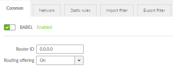
- Router ID
IP address, default = 0.0.0.0
M!DGE3 unit acts in the Babel network as a dynamic router. Every router is identified by an ID having the format of IP address. This IP address does not have to be ‘real’.
Router ID is shared across all dynamic protocols.
- Randomize ID
List box {On; Off}, default = “Off”
Advanced feature: Enables randomization of the upper 4 Bytes of the router identification. The lower 4 Bytes are set by a Router ID parameter. This feature might be used in a case the Babel node is often restarted resulting in refusing its messages by its neighbors.
- Routing offering
List box {On; Off}, default = “On”
Enables propagation of routing rules acquired from the neighbors. When disabled, the incoming rules are not propagated to other routers and this router behaves as an end point terminal – network paths are started or terminated in such a point, but do not travel through.
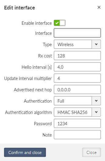
- Active
List box {On; Off}, default = “Off”
Enables / disables the interface.
- Interface
String {a..z A..Z 0..9}, max 16 char, default = <empty>Interfaces which will be used by Babel for searching the available connections. Name of an existing unit interface has to be used. Following interfaces can be used:
LAN – “if_” prefix must be used followed by Network interface name, e.g. “if_LAN-141”
VLAN – “if_” prefix must be used followed by Network interface name, ‘.’ dot and VLAN number, e.g. “if_LAN-141.29”
GRE L3 – “gre_tunX” where ‘X’ is the tunnel number, starting from zero
Cellular – “wwan”, “ext”
Interface MTU must be 1280 Bytes or bigger in order to operate Babel protocol correctly.
- Type
List box {Wired; Wireless}, default = “Wireless”
Type of network interface and also the type of link status evaluation. “Wired” link status is evaluated by checking the limit of received Hello packets – if not met, the link is considered down. “Wireless” link is status is evaluated using ETX criteria – each lost Hello packet gradually decreases the link metric.
- Rx cost
Number {1 – 65534}, default = 128
The cost of using this interface to receive packet from a neighbor. It is added to Babel path metric.
- Hello limit
Number {1 – 16}, default = 12
For “Wired” interface only: limit of received Hello packets from the 16 expected; if not met, the link is considered down.
- Hello interval
Number {0.1 – 327.0}, default = 4.0
Interval (in seconds) of sending Hello packets.
- Update interval multiplier
Number {2 – 30}, default = 4
Interval of sending the routing table update packets – to share the network topology information across the Babel network. The update interval is calculated as a multiplication of this parameter and Hello interval. The maximum length of the update interval (after the multiplication) is 655 seconds.
- Advertised next hop
IP address, default = 0.0.0.0
This is the Next hop address which is announced to neighbors to be routed over this interface. Should this interface serve more IP addresses, this parameter enables selection of which of the addresses should be used for this station in the network neighbors routing tables.
- Authentication
List box {None; Full; Only sign}, default = “None”
Enables packets authentication of Babel protocol.
Full – packets are signed during transfer and the signature is validated when receiving incoming packets. Packets with invalid signature are reported to the log and thrown away.
Only sign – Packets are signed during transfer and the signature is validated when receiving incoming packets. Packets with invalid signature are reported to the log and accepted. This settings is intended for gradual network switch to safe mode.
- Authentication algorithm
List box {HMAC SHA256; HMAC SHA384; HMAC SHA512; BLAKE2s-128; BLAKE2s-256; BLAKE2b-256; BLAKE2b-512}, default = “HMAC SHA256”
Selects the authentication algorithm. This parameter occurs only, if parameter Authentication is set either to “Full” or “Only sign”.
Each algorithm has its own passphrase length limit.
HMAC SHA256 – string length up to 128 char
HMAC SHA384 – string length up to 128 char
HMAC SHA512 – string length up to 128 char
BLAKE2s-128 – string length up to 32 char
BLAKE2s-256 – string length up to 32 char
BLAKE2b-256 – string length up to 64 char
BLAKE2b-512 – string length up to 64 char
- Passphrase
String {up to 128 char}
Defines the passphrase for packets authentication.
- Note
Optional comment.
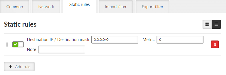
Pre-defined static routing rules to be exported over the Babel protocol. Maximum number of rules is 256.
- Active
List box {On; Off}, default = “On”
Enables / disables the static routing rule.
- Destination IP / Destination mask
IP address, default = 0.0.0.0/0
IP address and mask defining the exported routing rule address range.
- Metric
Number {0 – 65534}, default = 0
Routing rule metric value. The higher the value, the more “expensive” the path is.
- Note
Optional comment.
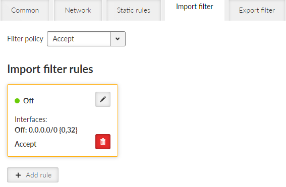
Babel import filter rules. The order of rules matters. Each incoming routing rule is processed by those Import filters. Maximum number of filter rules is 256.
- Active
List box {On; Off}, default = “On”
Enables / disables the filter rule.
- Filter network
List box {Off; Match; Not match}, default = “Off”
Method of the routing rule target range comparison.
- IP address / mask
IP address / mask, default = 0.0.0.0/0
IP address and mask defining the network range to be compared.
- Mask from
Number {0 – 32}, default = 0
- Mask to
Number {0 – 32}, default = 32
Definition of the enabled range of the mask length of the processed routing rule.
Examples:
Rule 0.0.0.0/0 {0,32} captures all IP ranges
Rule 192.168.1.0/24 {24,32} captures 192.168.1.0/24 and all subnets (for example 192.168.1.1/32)
Rule 10.9.8.7/32 {8,32} captures all ranges having the mask longer than 8 covering the address 10.9.8.7 (e.g. 10.9.0.0/16)
- Action
List box {Accept; Reject; Pass}, default = “Accept”
Type of action to be performed when the filter rules above matches the incoming routing rule. When “Pass” is selected, the packet processing continues.
- Set preference
List box {On; Off}, default = “Off”
When enabled, the Preference (see next parameter) will be set to this rule.
- Preference
Number {0 – 65535}, default = 210
Routing rule preference in the routing table (to be used when Set preference is enabled). The higher the number the better the preference.
- Local preferred source address
IP address, default = 0.0.0.0
Preferred source IP address for the locally generated packets. When disabled (default value 0.0.0.0 is used), the source IP address is set according to the outgoing interface.
- Note
Optional comment.
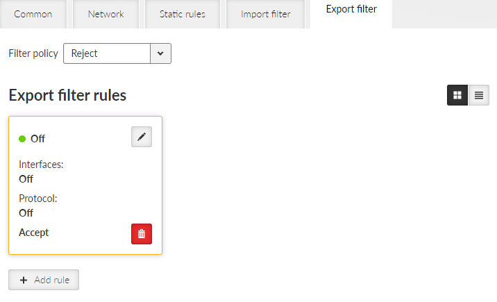
Babel export filter rules define set of routing rules to be exported from the unit to other Babel routers. The order of rules matters. Maximum number of filter rules is 256.
- Active
List box {On; Off}, default = “On”
Enables / disables the filter rule.
- Filter network
List box {Off; Match; Not match}, default = “Off”
Method of the routing rule target range comparison.
- IP address / mask
IP address / mask, default = 0.0.0.0/0
IP address and mask defining the network range to be compared.
- Mask from
Number {0 – 32}, default = 0
- Mask to
Number {0 – 32}, default = 32
Definition of the enabled range of the mask length of the processed routing rule.
- Filter protocol
List box {Off; Match; Not match}, default = “Off”
Selects the way how the routing rule source protocol is compared.
- Protocol
List box {System; BGP; BGP external; BGP internal; OSPF}, default = “System”
Selection of the protocol origin. “System” – stands for rules from the ordinary routing table.
- Filter BGP path
List box {Off; Is empty; Not empty}, default = “Off”
Compares BGP routing rule path if it is empty (i.e. the rule originates in this AS).
- Filter OSPF source
List box {Off; Match; Not match}, default = “Off”
Selects the way how the routing rule from the OSPF protocol is compared.
- OSPF source
List box {Internal; Inter-area; External type 1; External type 2}, default = “External type 2”
OSPF sources. “Internal” – stands for internally generated rule (e.g. interface range). “Inter-area” – stands for rule generated on the area borders.
- Filter OSPF tag
List box {Off; Match; Not match}, default = “Off”
OSPF tag based filtering method.
- OSPF tag
Number {0 – (232-1)}, default = 0
OSPF tag to be compared.
- Action
List box {Accept; Reject; Pass}, default = “Accept”
Defines what action is taken on the routing rule. When “Pass” is selected, the packet processing continues.
- Metric from other protocol
List box {Off; BGP MED; OSPF Metric 1; OSPF Metric 2; OSPF Metric Sum}, default = “Off”
Defines source of metric.
Off: The static Metric value (see the following parameter) is used.
BGP MED: MED (Multi-Exit Discriminator) rules from the BGP protocol. If the rule does not have a MED value filled in, the static Metric value is used.
OSPF metric 1: Metric of OSPF type 1. If the rule does not have a metric value filled in, the static Metric value is used.
OSPF metric 2: Metric of OSPF type 2. If the rule does not have a metric value filled in, the static Metric value is used.
OSPF metric sum: Sum of OSPF type 1 a type 2 metrics. If the rule does not have both metric values filled in, the static Metric value is used.
- Metric
Number {0 – 65534}, default = 0
Routing rule metric value. The higher the value, the more “expensive” the path is.
- Note
Optional comment.
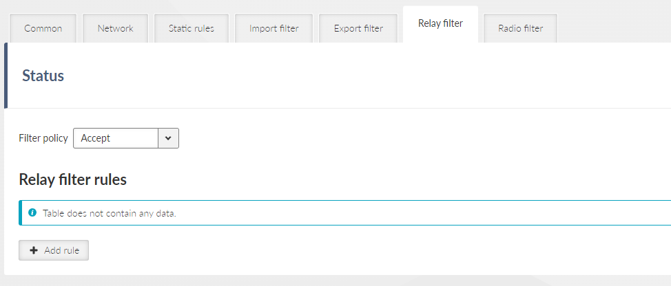
Relay filter selects what happens to a rule received from another Babel instance that were not captured in the filter. When disabled, the rules will not be forwarded to other routers and this station will act as a terminal where paths begin and end in the Babel network, but do not pass through it.
- Filter policy
List box {Accept; Reject}, default = “Accept”
- Enable rule
Check box {On; Off}, default = “On”
Activates/disables the rule
- Filter network
List box {Off; Match; Not match}, default = “Off”
Selects a way to compare the target range of the rule
Network IP/Network mask
IP address / mask, default = 0.0.0.0/0
Compares network prefix
Mask from
Number {0 – 32}, default = 0
Defines the allowed mask length range of the compared rule
Mask to
Number {0 – 32}, default = 32
Defines the allowed mask length range of the compared rule
- Action
List box {Accept; Reject; Pass}, default = “Accept”
Chooses what to do with the rule
- Filter metric
List box {Off; <; <=; >=; >}, default = “Off”
Selects a way to compare Babel metrics rules
Metric value
Number {0 – 65534}, default = 0
The compared value of the rule metric
- Increase metric
List box {Off; On}, default = “Off”
Enables incrementing Babel rule metrics on forwarding. It is used to penalize paths through this router. Only when Action is Accept or Pass.
Added metric
Number {1 – 65534}, default = 1
Value added to the rule metric
The Radio Filter is a function designed to improve the reliability of Babel, by ensuring user traffic is only routed over high-quality radio links. The filter excludes links with weak signals or poor quality. This prevents routing via unreliable links when signal is strong enough to transmit/receive short Babel Hello packets (Babel overhead/logic), but too weak for regular user traffic.
The filter operates by applying configurable Soft and Hard thresholds to Received Signal Strength (RSS) and Mean Square Error (MSE) in received Babel Hello packets. Packets exceeding the Hard limit are always discarded; packets falling between the thresholds are discarded with a probability that increases linearly as quality degrades; and only packets meeting the Soft threshold are always accepted.
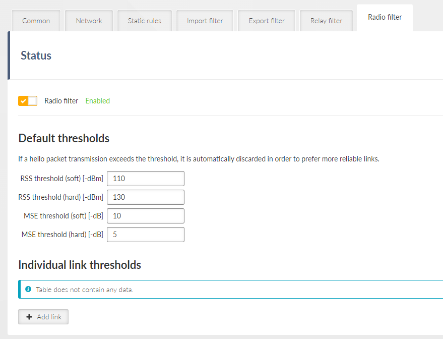
The Default thresholds contain settings for filtering Babel Hello packets based on the quality metrics of the received signal, these settings are applied to all links unless specific individual thresholds are configured.
- RSS threshold (soft)
Number {50 – 150}, default = 110
RSS level limits [-dBm] of the received Hello packet
Soft limit is the worst value below which the packet is not discarded
- RSS threshold (hard)
Number {50 – 150}, default = 130
RSS level limits [-dBm] of the received Hello packet
Hard limit is the best value to always discard the packet
Note Must be Soft threshold <= Hard threshold
- MSE threshold (soft)
Number {0 – 60}, default = 10
MSE data level limits [-dB] of the received Hello packet
Soft limit is the worst value below which the packet is not discarded
- MSE threshold (hard)
Number {0 – 60}, default = 5
MSE data level limits [-dB] of the received Hello packet
Hard limit is the best value to always discard the packet
Note Must be Soft threshold >= Hard threshold
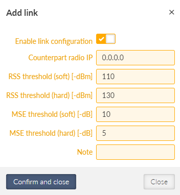
Individual link thresholds contain settings for filtering Babel Hello packets with specific remote based on the source link address.
- Enable link configuration
List box {Off; On}, default = “On”
Activates individual settings
- Counterpart radio IP
IP address, default = 0.0.0.0
Radio IP address of the Hello packet source for which the individual filter setting applies
- Note
Optional note
Advanced settings
- Filter poisoned routes
List box {Off; On}, default = “Off”
Enables filtering of poisoned route rules (which arise, for example, when a routing rule is revoked) when importing from the Babel protocol to the babel_ipv4 table (and thus to other tables). It does not affect their retranslation (special behavior of the Babel protocol).
- Filter routes with high metric
List box {Off; On}, default = “Off”
Enables filtering of rules with metrics higher than the set metric when importing from the Babel protocol to the babel_ipv4 table. These rules cannot be used for routing in the station or propagated to other stations. They serve to limit the size of routing tables, but if set incorrectly, they can result in remote network stations having no valid path between them.
- Maximal accepted route metric
Number {1 – 65534}, default = 1000
The highest value of the imported routing rule metric that will still be accepted.
Open Shortest Path First (OSPF) is a routing protocol for Internet Protocol (IP) networks. It uses a link state routing (LSR) algorithm and falls into the group of interior gateway protocols (IGPs), operating within a single autonomous system (AS). OSPF Version 2 defined in RFC 2328 (1998) for IPv4 is implemented in the M!DGE3 router. OSPF provides Layer 2 dynamic routing. In the context of M!DGE3 networks it is typically used for the backhaul network routing.
OSPF splits the network into “areas” to simplify the network topology. There is a primary “backbone” (0.0.0.0) area and the other areas are connected to this backbone area via border routers.
The route decision process is affected by the path “metric”. There are two types of metrics:
Metric Type 1 – path length; individual interfaces pass-over costs are added.
Metric Type 2 – is setup on the rules which are exported to the OSPF from outside. Rules having metric ‘Type 2’ are always treated as worse (i.e. longer path) comparing to metric ‘Type 1’.
Routers in a specific area are always connected via interfaces.
An address range can be defined for an interface where is the OSPF working. Multiple address ranges can be defined (behaving as another interface).
Router to router interconnection can be protected by encryption with the passphrase.
Specific “Cost” is defined for each interface which is added to metric ‘Type 1.’
There are multiple types of interfaces:
Stub – interface only announces to OSPF: its presence and its address ranges to be propagated further to the network.
Broadcast – to be used in the network where all the participants always hear each other (Ethernet). Designated Router (DR) and Backup DR (BDR) are setup between the neighbors. They are responsible for the update propagation (broadcast).
NBMA (Non-Broadcast Multiple Access) – to be used in the network where only specific participants can communicate between each other; all the participants hear each other but multicast is not available. DR and BDR is setup.
Point2Point – network having only two participants. They discover each other using multicast.
Point2Multipoint – network where only predefined pairs of participants can hear each other (e.g. star topology); multicast is not available.
Static rules can be defined. Such a routing rules are propagated to the network from this router.
It is possible to define exported routing rules aggregation or specific routing rule hiding.
It is possible to control the routing rules which are imported into the M!DGE3 unit from the OSPF protocol and those that are exported into the OSPF protocol from the unit by using ‘filters’.
Export filters – to control rules exported from the unit to the OSPF protocol which is propagating them further.
Import filters – to control rules imported from the OSPF into the unit.
- Active
List box {On; Off}, default = “Off”
Enables the dynamic routing and the OSPF protocol.
- Router ID
IP address, default = 0.0.0.0
M!DGE3 unit acts in the OSPF network as a dynamic router. Every router is identified by an ID having the format of IP address. This IP address does not have to be ‘real’. Router ID is shared across all dynamic protocols.
- Instance ID
Number {0 – 255}, default = 0
OSPF protocol instance number. This number is needed in case of running multiple OSPF protocols (for example on the border of 2 independent OSPF networks).
OSPF areas M!DGE3 unit belongs to are described here. Maximum number of areas is 32.
- Enable / Disable
Enables / disables the specific area.
- Area ID
IP address, default = 0.0.0.0
OSPF area identifier. The ID has a format of an IP address. This IP address does not have to be ‘real’. The ‘Router ID’ value is used typically. The default value of 0.0.0.0 is called ‘backbone’ and it has to be present somewhere in the OSPF network.
- Stub area
Click box {On; Off}, default = “Off”
Defines if the area is of a ‘stub’ type – which means, the traffic is not routed through such an area. Every traffic is originated or terminated in the ‘stub’ area.
- Stub default GW (ADVANCED parameter)
List box {On; Off}, default = “On”
If ‘On’ – only default GW is routed to the ‘stub’ area. Of ‘Off’ – individual routes are routing the traffic into the area. It may be effective to disable this parameter when multiple border routers are present.
- Note
Optional comment. It is a good practice to enter some descriptive area name since this value is displayed (when filled) instead of the Area ID as an Area name in other configuration dialogs (e.g. Networks configuration).
OSPF interfaces of the respective OSPF area are defined here. Maximum number of interfaces is 128.
- Active
List box {On; Off}, default = “Off”
Enables / disables the interface.
- Interface
String {a..z A..Z 0..9}, max 16 char, default = <empty>
OSPF interface name. Name of an existing unit interface has to be used. Following interfaces can be used:
LAN – “if_” prefix must be used followed by Network interface name, e.g. “if_LAN-141”
VLAN – “if_” prefix must be used followed by Network interface name, ‘.’ dot and VLAN number, e.g. “if_LAN-141.29”
GRE L3 – “gre_tunX” where ‘X’ is the tunnel number, starting from zero
Cellular – “wwan”, “ext”
- IP address / mask
IP address / mask, default = 0.0.0.0/0
IP address and mask of the address range above which the OSPF protocol will be working on this interface. The default value is 0.0.0.0/0, which means the whole address range on this interface is available for the OSPF protocol.
- Network type
List box {Broadcast; Point2Point; Point2Multipoint; NBMA; Stub}, default = “Broadcast”
Defines the type of the network behind the interface.
- Cost
Number {1 – 65535}, default = 10
The cost of traffic over this interface. The higher the Cost, the worse the path. It is added to OSPF metric ‘Type 1’.
- Hello interval
Number {1 – 3600}, default = 10
Interval (in seconds) of sending Hello packets. The interval must be the same for the all participants of the given interface.
- Poll interval
Number {1 – 3600}, default = 20
Interval (in seconds) of sending Hello packets to inactive neighbors in the NMBA type of interface.
- Retransmit interval
Number {1 – 3600}, default = 5
Interval (in seconds) of repeating unacknowledged packets.
- Dead count
Number {2 – 64}, default = 4
Number of lost Hello packets from the neighbor to treat the connection as interrupted.
- TTL security
List box {On; Off}, default = “On”
Protection against OSPF packets spoofing.
- Authentication, Passphrase
List box {None; Keyed MD5 (OSPFv2); HMAC SHA256; HMAC SHA384; HMAC SHA512}, default = “None”
Selection of a method to authenticate the OSPF messages. Passphrase is used as a secret key for the selected hash function. Maximum length of the passphrase is 128 characters.
- Priority
Number {0 – 255}, default = 1
Priority is used to select primary or backup router responsible for the routing updates propagation. The higher the number, the higher the priority. ‘0’ states the router cannot be used as a primary or backup router.
- Use broadcast
List box {On; Off}, default = “Off”
Defines if OSPF packets distribution is provided using multicasts (default behavior) or broadcasts (nonstandard behavior).
- Note
Optional comment. It is possible to enter some descriptive OSPF interface name. This value is used (when filled) instead of the original Interface identification as an Interface name in other configuration dialogs (e.g. Neighbors configuration).
Network neighbors of Point2Multipoint and NBMA types of OSPF interfaces are defined here. Maximum number of neighbors is 512.
- Active
List box {On; Off}, default = “Off”
Enables / disables the interface.
- Interface
List box {list of existing OSPF interfaces}
OSPF interface the neighbor belongs to. The interface – Note value is used when defined. The interface – Interface value is used otherwise.
- IP
IP address, default = 0.0.0.0
IP address of the neighbor.
- Note
Optional comment.
The Networks table modifies networks announced out of the area. It enables partial networks aggregation into the common prefixes or specific network hiding. Maximum number of rules is 256.
- Active
List box {On; Off}, default = “Off”
Enables / disables the interface.
- Area
List box {list of existing OSPF areas}
OSPF area the record belongs to.
- IP address / mask
IP address / mask, default = 0.0.0.0/0
IP address and mask of the range (i.e. network) which will be aggregated or hidden.
- Action
List box {Aggregate; Hide}, default = “Aggregate”
Aggregate – small network prefixes will be exported from this area aggregated into this range (defined by IP / mask)
Hide – this network prefix will be hidden and will not be exported
Example:
Area 0.0.0.1 exports two subnets: 192.168.1.0/24 and 192.168.2.0/24. Area border router between Area 0.0.0.1 and 0.0.0.0 defines a rule for network aggregation: 192.168.0.0/16. As a result of this, the area border router announces to the area 0.0.0.0 only one route 192.168.0.0/16 instead of the two individual routes.- Note
Optional comment.
Pre-defined static routing rules to be exported over the OSPF protocol. Maximum number of rules is 256.
- Active
List box {On; Off}, default = “Off”
Enables / disables the static routing rule.
- Destination IP / Destination mask
IP address, default = 0.0.0.0/0
IP address and mask defining the exported routing rule address range.
- Metric type
List box {Type 1; Type 2}, default = “Type 1”
Metric type of the routing rule. Metric 1 is added to the path cost. Metric 2 stays apart and compared to metric 1 is always bigger.
- Metric
Number {1 – 65535}, default = 1000
Routing rule metric value.
- OSPF tag
Number {0 – (232-1)}, default = 0
OSPF tag is added to a rule at the moment of its insertion to the network. The tag travels through the OSPF without any modification so it can be used to distinguish the rule in the filters.
- Note
Optional comment.
OSPF import filter rules. The order of rules matters. Each incoming routing rule is processed by those Import filters. Maximum number of filter rules is 256.
- Active
List box {On; Off}, default = “Off”
Enables / disables the filter rule.
- Filter network
List box {Off; Match; Not match}, default = “Off”
Method of the routing rule target range comparison.
- IP address / mask
IP address / mask, default = 0.0.0.0/0
IP address and mask defining the network range to be compared.
- Mask from
Number {0 – 32}, default = 0
- Mask to
Number {0 – 32}, default = 32
Definition of the enabled range of the mask length of the processed routing rule.
Examples:
Rule 0.0.0.0/0{0,32} captures all IP ranges
Rule 192.168.1.0/24{24,32} captures 192.168.1.0/24 and all subnets (for example 192.168.1.1/32)
Rule 10.9.8.7/32{8,32} captures all ranges having the mask longer than 8 covering the address 10.9.8.7 (e.g. 10.9.0.0/16)
- Filter source
List box {Off; Match; Not match}, default = “Off”
Method of the OSPF routing rule source comparison.
- Source
List box {Internal; Inter-area; External type 1; External type 2}, default = “External type 1”
Source types comments:
Internal – internally generated rule, for example interface range
Inter-area – rule generated on the area border
- Filter OSPF tag
List box {Off; Match; Not match}, default = “Off”
Method of the OSPF routing rule OSPF tag comparison
- OSPF tag
Number {0 – (232-1)}, default = 0
OSPF tag to be compared.
- Action
List box {Accept; Reject; Pass}, default = “Accept”
Type of action to be performed when the filter rules above matches the incoming routing rule.
- Set preference
List box {On; Off}, default = “Off”
When enabled, the Preference (see next parameter) will be set to this rule.
- Preference
Number {0 – 65535}, default = 200
Routing rule preference in the routing table (to be used when Set preference is enabled). The higher the number the better the preference.
- Local preferred source address
IP address, default = 0.0.0.0
Preferred source IP address for the locally generated packets. When disabled (default value 0.0.0.0 is used), the source IP address is set according to the outgoing interface.
- Note
Optional comment.
OSPF export filter rules define set of routing rules to be exported from the unit into the OSPF area. The order of rules matters. Maximum number of filter rules is 256.
- Active
List box {On; Off}, default = “Off”
Enables / disables the filter rule.
- Note
Optional comment.
- Filter network
List box {Off; Match; Not match}, default = “Off”
Selects a method of the routing rule destination range comparison.
- IP address / mask
IP address / mask, default = 0.0.0.0/0
IP address and mask defines the network prefix to be compared.
- Mask from
Number {0 – 32}, default = 0
- Mask to
Number {0 – 32}, default = 32
Definition of the enabled range of the mask length of the processed routing rule.
- Filter protocol
List box {Off; Match; Not match}, default = “Off”
Selects the way how the routing rule source protocol is compared.
- Protocol
List box {System; BGP; BGP external; BGP internal}, default = “System”
Selection of the protocol origin. “System” – stands for rules from the ordinary routing table.
- Filter BGP path
List box {Off; Is empty; Not empty}, default = “Off”
Compares BGP routing rule path if it is empty (i.e. the rule originates in this AS).
- Action
List box {Accept; Reject; Pass}, default = “Accept”
Defines what action is taken on the routing rule. “Pass” continues in processing.
Border Gateway Protocol (BGP) is a standardized exterior gateway protocol designed to exchange routing and reachability information among autonomous systems. BGP is classified as a path-vector routing protocol, and it makes routing decisions based on paths, network policies, or rule-sets configured by a network administrator.
BGP splits the network into Autonomous Systems (AS) which are identified by a specific number. Individual BGP routers are interconnected with their neighbors using TCP connections. Any connection can travel over multiple hops. Any connection can be secured using MD5 signatures.
Connections inside the AS are called ‘internal’ (iBGP):
All BGP routers within given AS must be fully interconnected – every router must have connection to all other routers.
It is possible to define ‘Route reflectors’ – they must be fully interconnected. The other routers behave as Route reflector clients and they need a connection to their reflector only. Route reflector and its clients form a ‘cluster’. It is possible to create a cluster with multiple Route reflectors for the purpose of backup.
The iBGP router having a higher local preference will be preferred during the internal AS path selection.
Connections to another AS are called ‘external’ (eBGP):
It is possible to communicate from the router to the neighbor AS the MED (Multi-Exit Discriminator) metric designating which of the AS border routers will be used as an input point.
When the routing rules are spread across the multiple AS, those AS are added into the accumulated path (BGP path). Path length is the primary criteria during the decision which of the routing rules will be used.
It is possible to prescribe routing rules toward this router which will be spread across the network (Static rules).
It is possible to control the routing rules which are imported into the M!DGE3 unit from the BGP protocol and those that are exported into the BGP protocol from the unit by using ‘filters’.
Import IGP filter – controls which of the routing rules from the BGP are accepted to the dynamic routing table and how
Export IGP filter – controls which of the routing rules from the dynamic routing table are exported to the BGP and how
Import OUT filter – controls which of the routing rules from the other AS are accepted to the BGP and how
Export OUT filter – controls which of the routing rules are exported from the BGP to other AS and how
Routing rules passed on between iBGP and BGP tables are not filtered
- Active
List box {On; Off}, default = “Off”
Enables the dynamic routing and the BGP protocol.
- Router ID
IP address, default = 0.0.0.0
M!DGE3 unit acts in the BGP network as a dynamic router. Every router is identified by an ID having the format of an IP address. This IP address does not have to be ‘real’. Router ID is shared with the OSPF protocol.
- Local AS
Number {0 – (232-1)}, default = 65000
Local Autonomous System identification number. AS numbers are assigned by IANA. Part of the range is reserved for private network usage: 64512 – 65534 and 4200000000 – 4294967294. AS numbers from this range can be safely used by anyone.
- Preference
Number {0 – (232-1)}, default = 100
Router preference within the local AS. The higher the number, the higher the preference.
- MED (Multi-Exit Discriminator)
List box {Off; Static; OSPF metric 1}, default = “Off”
Setting of MED (Multi-Exit Discriminator) on the routing rules being exported to other AS. MED makes it possible to advertise which of the routers in the local AS is the preferred input point to the AS. “Static” option sets the fixed value for all rules (Static MED). “OSPF metric 1” copies the OSPF metric to MED; for the rules which are not from the OSPF it enters the fixed value Static MED.
- Static MED
Number {0 – (232-1)}, default = 0
Metric to be used for the preferred input point to the AS selection (see MED (Multi-Exit Discriminator) description). The higher the number the lower the preference.
- Route reflector
List box {Off; On}, default = “Off”
Enables the Route reflector function on this router. iBGP requires connection in between all routers under normal circumstances. Route reflector makes it possible to avoid this requirement by distributing routing updates to all its clients. Such clients do not need any other connection except connection to this Route reflector. Route reflector and its clients form a ‘cluster’. See more details at the beginning of the BGP chapter.
- Cluster ID type
List box {Router ID; Manual}, default = “Router ID”
Controls the iBGP cluster identification. Cluster identification must be the same inside the cluster and it has to be different in another cluster. If the “Router ID” is selected, the Router ID value is used as a cluster id.
- Cluster ID
IP address, default = 0.0.0.0
Cluster identification in the format of an IP address. This IP address does not have to be ‘real’ (valid).
Neighboring BGP routers. Maximum number of neighbors is 256.
- Active
List box {On; Off}, default = “On”
Enables the specific neighbor.
- Note
Optional comment.
- Neighbor type
List box {Internal; External}, default = “External”
Neighbor router type selection. “Internal” neighbor belongs to the same AS (iBGP). “External” belongs to other AS (eBGP).
- Neighbor AS
Number {0 – (232-1)}, default = 65000
Neighbor AS number.
- Neighbor IP
IP address, default = 0.0.0.0
Neighbor router IP address.
- Local IP of the connection
IP address, default = 0.0.0.0
Local IP address of the connection. Default value 0.0.0.0 provides automatic set up of this address – from the routing.
- Neighbor connection
List box {Direct; Multihop}, default = “Direct”
Network connection type between the neighbors. “Direct” means direct – one hop – connection. This is typical for eBGP routers. “Multihop” means connection over the multiple routers. This is typical for iBGP routers.
- MD5 authentication
List box {On; Off}, default = “Off”
Enables BGP packets authentication using TCP MD5 Signature extension.
- Passphrase
String {up to 80 characters}
Passphrase for the MD5 authentication.
- Passive
List box {On; Off}, default = “Off”
Passive BGP router does not initiate connection to a neighbor, it is waiting for the neighbor activity.
- Hold interval [s]
Number {3 – 10800}, default = 240
Time (in seconds) to wait for the keepalive message from the neighbor. It is negotiated with the neighbor. When it expires, the connection is treated as interrupted.
- Keepalive interval [s]
Number {1 – 3600}, default = 80
Period (in seconds) of sending keepalive messages. It should not be longer than 1/3 of the Hold interval.
- Connection retry interval [s]
Number {1 – 3600}, default = 120
Time (in seconds) to wait before trying to re-connect the interrupted connection.
- TTL security
List box {On; Off}, default = “On”
Protection against BGP packets spoofing. [PP1] The Generalized TTL Security Mechanism (GTSM – RFC 5082) is used. BGP transmits packets with known TTL value. Incoming packets having lower than expected value (expected number of hops) are discarded.
- Expected hops
Number {2 – 32}, default = 2
Number of expected hops between the neighbors.
- Route reflector client
List box {On; Off}, default = “Off”
Defines if this neighbor is a client of this Route reflector.
- Set cost
List box {On; Off}, default = “Off”
Enables to set a specific Cost of the BGP connection.
- Cost
Number {0 – (232-1)}, default = 10
The cost of connection to this neighbor. The higher the number the higher the cost. It enables to make decisions inside the router between multiple paths from the same neighbor.
- Next hop self
List box {Off; Always; Internal; External}, default = “Off”
Defines it the exported routing rules should have ‘next hop’ addresses overwritten to the address of this router. “Internal” overwrites only the rules from the local AS. “External” overwrites only the rules from the other AS.
Pre-defined static routing rules to be exported over the BGP protocol. Maximum number of rules is 256.
- Active
List box {On; Off}, default = “Off”
Enables / disables the static routing rule.
- Destination IP / Destination mask
IP address, default = 0.0.0.0/32
IP address and mask defining the exported routing rule destination address range.
- Note
Optional comment.
Import IGP filter [PP1] rules. The order of rules matters. Maximum number of filter rules is 256.
- Filter policy
List box {Accept; Reject}, default = “Reject”
Defines what action is taken on the routing rules which were not captured (i.e. fallback) in the Import IGP filter.
- Active
List box {On; Off}, default = “On”
Enables / disables the filter rule.
- Note
Optional comment.
- Filter network
List box {Off; Match; Not match}, default = “Off”
Selects a method of the routing rule destination range comparison.
- IP address / mask
IP address / mask, default = 0.0.0.0/0
IP address and mask defines the network prefix to be compared
- Mask from
Number {0 – 32}, default = 0
- Mask to
Number {0 – 32}, default = 32
Definition of the enabled range of the mask length of the processed routing rule.
- Filter source
List box {Off; Internal; External}, default = “Off”
Selection based on the routing rule source. “Internal” selects rules received from the internal (iBGP) connection. “External” selects rules received from the other AS (eBGP).
- Filter BGP path
List box {Off; Is empty; Not empty; Contain; Not contain}, default = “Off”
Filtering based on the BGP Path (routing rule path over different AS). “Is empty” – defines an empty path (routing rule from the local AS). “Contain” – defines paths containing specific AS.
- Path position
List box {Any; Neighbor; Source}, default = “Any”
Selects position of the specific AS (Path AS). “Any” – anywhere on the path. “Neighbor” – the path was received from this AS (last on the path). “Source” – routing rule was originated from this AS (first on the path).
- Path AS
Number {0 – (232-1)}, default = 65000
The number of the AS searched for.
- Action
List box {Accept; Reject; Pass}, default = “Accept”
Defines what action is taken on the captured [PP1] routing rule. “Pass” continues in processing.
- Set preference
List box {Off; On}, default = “Off”
Defines if the specific Preference will be set up for this rule.
- Preference
Number {0 – 65535}, default = 100
Routing rule preference in the routing table. The higher the number the higher the preference.
- Local preferred source address
IP address, default = 0.0.0.0
Preferred source IP address for the locally generated packets. When disabled (default value 0.0.0.0 is used), the source IP address is set according to the outgoing interface.
Export IGP filter rules. The order of rules matters. Maximum number of filter rules is 256.
- Filter policy
List box {Accept; Reject}, default = “Reject”
Defines what action is taken on the routing rules which were not captured (i.e. fallback) in the Export IGP filter.
- Active
List box {On; Off}, default = “On”
Enables / disables the filter rule.
- Note
Optional comment.
- Filter network
List box {Off; Match; Not match}, default = “Off”
Selects a method of the routing rule destination range comparison.
- IP address / mask
IP address / mask, default = 0.0.0.0/0
IP address and mask defines the network prefix to be compared
- Mask from
Number {0 – 32}, default = 0
- Mask to
Number {0 – 32}, default = 32
Definition of the enabled range of the mask length of the processed routing rule.
- Filter protocol
List box {Off; Match; Not match}, default = “Off”
Selects the way how the routing rule source protocol is compared.
- Protocol
List box {System; OSPF}, default = “System”
Selection of the protocol origin. “System” – stands for rules from the ordinary routing table. “OSPF” stands for rules from the OSPF protocol.
- Filter OSPF source
List box {Off; Match; Not match}, default = “Off”
Selects the OSPF routing rule source comparison mode.
- OSPF source
List box {Internal; Inter-area; External type 1; External type 2}, default = “External type 2”
OSPF sources. “Internal” – stands for internally generated rule (e.g. interface range). “Inter-area” – stands for rule generated on the area borders.
- Filter OSPF tag
List box {Off; Match; Not match}, default = “Off”
Selects the way of filtering based on OSPF tag.
- OSPF tag
Number {0 – (232-1)}, default = 0
OSPF tag to be compared. The tag is added to a rule when inserted to OSPF.
- Action
List box {Accept; Reject; Pass}, default = “Accept”Defines what action is taken on the routing rule. “Pass” continues in processing.
Import OUT filter [PP1] rules. The order of rules matters. Maximum number of filter rules is 256.
- Filter policy
List box {Accept; Reject}, default = “Accept”
Defines what action is taken on the routing rules which were not captured (i.e. fallback) in the Import OUT filter.
- Filter limit
Number {1 – 65535}, default = 1024
Limit of the accepted routing rules from the neighbor. The limit applies before this Import OUT filter. Excess rules are dropped.
- Active
List box {On; Off}, default = “On”
Enables / disables the filter rule.
- Note
Optional comment.
- Filter network
List box {Off; Match; Not match}, default = “Off”
Selects a method of the routing rule destination range comparison.
- IP address / mask
IP address / mask, default = 0.0.0.0/0
IP address and mask defines the network prefix to be compared
- Mask from
Number {0 – 32}, default = 0
- Mask to
Number {0 – 32}, default = 32
Definition of the enabled range of the mask length of the processed routing rule.
- Filter BGP path
List box {Off; Is empty; Not empty; Contain; Not contain}, default = “Off”
Filtering based on the BGP Path (routing rule path over different AS). “Is empty” – defines an empty path (routing rule from the local AS). “Contain” – defines paths containing specific AS.
- Path position
List box {Any; Neighbor; Source}, default = “Any”
Selects position of the specific AS (Path AS). “Any” – anywhere on the path. “Neighbor” – the path was received from this AS (last on the path). “Source” – routing rule originates from this AS (first on the path).
- Path AS
Number {0 – (232-1)}, default = 65000
The number of the AS searched for.
- Action
List box {Accept; Reject; Pass}, default = “Accept”
Defines what action is taken with the matching routing rule. “Pass” continues in processing.
- Prepend local AS
Number {0 – 8}, default = 0
Enables to append (even multiple times) local AS number to the BGP path end – making the path virtually longer. The longer path is handicapped during the comparisons and selections.
Export OUT filter rules. The order of rules matters. Maximum number of filter rules is 256.
- Filter policy
List box {Accept; Reject}, default = “Accept”
Defines what action is taken on the routing rules which were not captured (i.e. fallback) in the Export OUT filter.
- Active
List box {On; Off}, default = “On”
Enables / disables the filter rule.
- Note
Optional comment.
- Filter network
List box {Off; Match; Not match}, default = “Off”
Selects a method of the routing rule destination range comparison.
- IP address / mask
List box {Off; Match; Not match}, default = “Off”
IP address and mask defines the network prefix to be compared
- Mask from
Number {0 – 32}, default = 0
- Mask to
Number {0 – 32}, default = 32
Definition of the enabled range of the mask length of the processed routing rule.
- Filter protocol
List box {Off; Match; Not match}, default = “Off”
Selects the way how the routing rule source protocol is compared.
- Protocol
List box {System; OSPF; BGP; BGP external; BGP internal}, default = “System”
Selection of the protocol origin. “System” – stands for rules from the ordinary routing table.
- Filter OSPF tag
List box {Off; Match; Not match}, default = “Off”
Selects the way of filtering based on OSPF tag.
- OSPF tag
Number {0 – (232-1)}, default = 0
OSPF tag to be compared. The tag is added to a rule when inserted to OSPF.
- Filter BGP path
List box {Off; Is empty; Not empty; Contain; Not contain}, default = “Off”
Filtering based on the BGP Path (routing rule path over different AS). “Is empty” – defines an empty path (routing rule from the local AS). “Contain” – defines paths containing specific AS.
- Path position
List box {Any; Neighbor; Source}, default = “Any”
Selects position of the specific AS (Path AS). “Any” – anywhere on the path. “Neighbor” – the path was received from this AS (last on the path). “Source” – routing rule was originated from this AS (first on the path).
- Path AS
Number {0 – (232-1)}, default = 65000
The number of the AS searched for.
- Action
List box {Accept; Reject; Pass}, default = “Accept”
Defines what action is taken on the routing rule. “Pass” continues in processing.
A firewall is a critical security tool that monitors and controls network traffic based on predefined rules. It acts as a protective barrier, filtering data packets to prevent unauthorized access, malicious attacks, and other threats.
Firewalls operate at Layer 2 (L2) and Layer 3 (L3) of the OSI model, offering features like packet filtering, traffic inspection, and stateful connection tracking for robust network protection.
An L2 firewall operates at the data link layer, managing traffic based on MAC addresses and Ethernet frames within the same local network or broadcast domain. It can block or allow traffic based on source and destination MAC addresses, VLAN tags, or specific Ethernet frame types. L2 firewalls are essential for enforcing network segmentation, controlling device access, and optimizing bandwidth in narrowband networks.
L2 firewalls enable MAC address filtering to control network access. Administrators can define rules to allow or block traffic from specific devices, enhancing security and isolating compromised endpoints.
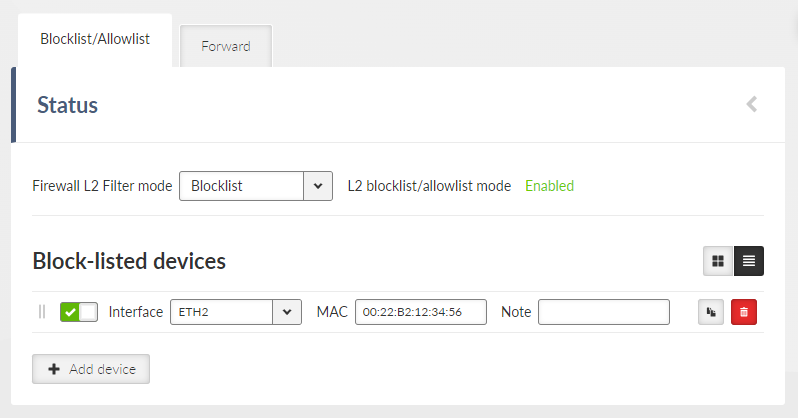
- Filter mode
List box {Off; Blocklist; Allowlist}, default = “Off”
- Blocklist
The MAC addresses listed in the table are blocked, i.e. all packets to/from them are discarded. The traffic to/from other MAC addresses is allowed.
- Allowlist
Only the MAC addresses listed in the table are allowed, i.e. only packets to/from them are allowed. The traffic to/from other MAC addresses is blocked.
- Active
List box {Off; On}, default = “On”
If “On”, Layer 2 Linux firewall rule is activated.
- Interface
List box {All; ETH1..ETH5}, default = “All”
- MAC
IPv4 MAC address
These parameters are only visible when “Enable blocklist/allowlist rules logging” is checked.
- Enable rule logging
List box {On, Off}, default = “On”
Activate logging for your blocklist/allowlist rule.
- Rule logging identifier
String matching the regular expression “^[a-zA-Z0-9_-]{0,12}$”, default = <empty>
Set an optional identifier for your rule in the log.
- Rule logging severity
List box {Emergency, Alert, Critical, Error, Warning, Notice, Informational, Debug}, default = “Notice”
Select the log severity level for your rule.
| Note | |
|---|---|
L2 firewall settings do not impact the local ETH access, i.e. settings never deny access to a locally connected M!DGE3 (web interface, ping, …). |
Forward rules manage how Ethernet frames are handled within the broadcast domain. These rules control communication paths, enforce segmentation, and filter unwanted traffic. Forward filtering applies to packets traversing a bridge but not to traffic originating from or destined for the station.
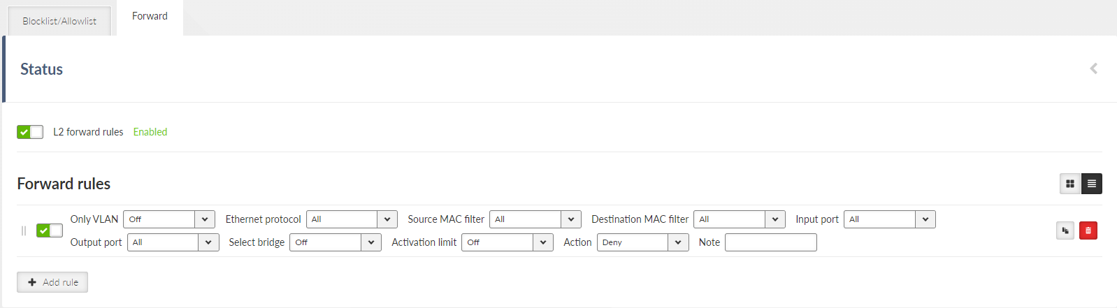
Each individual firewall rule is described by following parameters:
- Enable rule
Check box {On; Off}, default = “Off”
Enables / disables L3 firewall rule.
- Only VLAN
List box {Off; On}, default = “Off”
Enables packet filtering for a specific VLAN and deep packet inspection.
If enabled:
- VLAN
Number (0-4094), default = 1
ID of the filtered VLAN
- Ethernet protocol
List box {All; Not VLAN; All VLAN; IPv4; IPv6; ARP; Other}, default = “All”
Filter based on EtherType (protocol carried in the Ethernet frame).
- Source MAC filter
List box {All; Mask; Unicasts; Multicasts; Broadcasts}, default = “All”
Enables filtering based on the source MAC address of the packet.
For Mask option:
- Source MAC address
Address used to compare against the source MAC address of packets.
- Source MAC mask
Mask used to compare against the source MAC address of packets.
- Destination MAC filter
List box {All; Mask; Unicasts; Multicasts; Broadcasts}, default = “All”
Enables filtering based on the destination MAC address of the packet.
For Mask option:
- Destination MAC address
Address used to compare against the destination MAC address of packets.
- Destination MAC mask
Mask used to compare against the destination MAC address of packets.
- Input port
List box {All; Radio; All ETH; ETH1; ETH2; ETH3; ETH4; ETH5; GRE L2; OpenVPN L2; Other”}, default = “All”
Filters based on the port that the packet entered the bridge through.
For Other option:
- Input port name
String {0–16 char}, default = <empty>
Name of the input port. Must be the name of an existing interface used as a bridge port.
- Output port
List box {All; Radio; All ETH; ETH1; ETH2; ETH3; ETH4; ETH5; GRE L2; OpenVPN L2; Other”}, default = “All”
Filters based on the port that the packet exits the bridge through.
For Other option:
- Output port name
String {0–16 char}, default = <empty>
Name of the output port. Must be the name of an existing interface used as a bridge port.
- Select bridge
List box {Off; On}, default = “Off”
Enables limiting of the rule to a specific bridge. The rule will only be applied to packets that pass through the selected bridge.
- Activation limit
List box {Off; On}, default = “Off”
Enables limiting the number of times the rule can be triggered per time unit.
If enabled:
- Frame count
Number (1-10000), default = 3
Average packet/activation rate limit per time unit.
- Measurement period
List box {Second, Minute, Hour, Day}, default = “Minute”
Time unit for limiting the packet/activation rate.
- Burst size
Number (1-10000), default = 3
Initial and maximum number of TBF tokens. After a period of inactivity, TBF allows a burst of traffic to pass through at once. Must be greater than or equal to Frame count.
- Action
List box {Deny; Allow}, default = “Deny”
Selects the action to be taken on a packet that matches the configured filter.
These parameters are only visible when “Enable forward rules logging” is checked.
- Enable rule logging
List box {On, Off}, default = “On”
Activate logging for your forward rule.
- Rule logging identifier
String matching the regular expression “^[a-zA-Z0-9_-]{0,12}$”, default = <empty>
Set an optional identifier for your rule in the log.
- Rule logging severity
List box {Emergency, Alert, Critical, Error, Warning, Notice, Informational, Debug}, default = “Notice”
Select the log severity level for your rule.
An L3 firewall operates at the network layer, filtering traffic based on IP addresses and protocols. It enables control over data packets as they traverse different networks, allowing administrators to block or permit traffic based on source and destination IPs, port numbers, and protocol types. L3 firewalls are crucial for enforcing inter-network security, managing traffic flow, and protecting against external threats.
Forward rules in an L3 firewall control how IP packets are routed between networks. These rules specify whether traffic should be allowed or blocked as it passes through the router. Packets coming from addresses on the Blocklist are automatically dropped. By applying forward rules, administrators can manage traffic flow, enforce security policies, and prevent unauthorized access between different network segments.
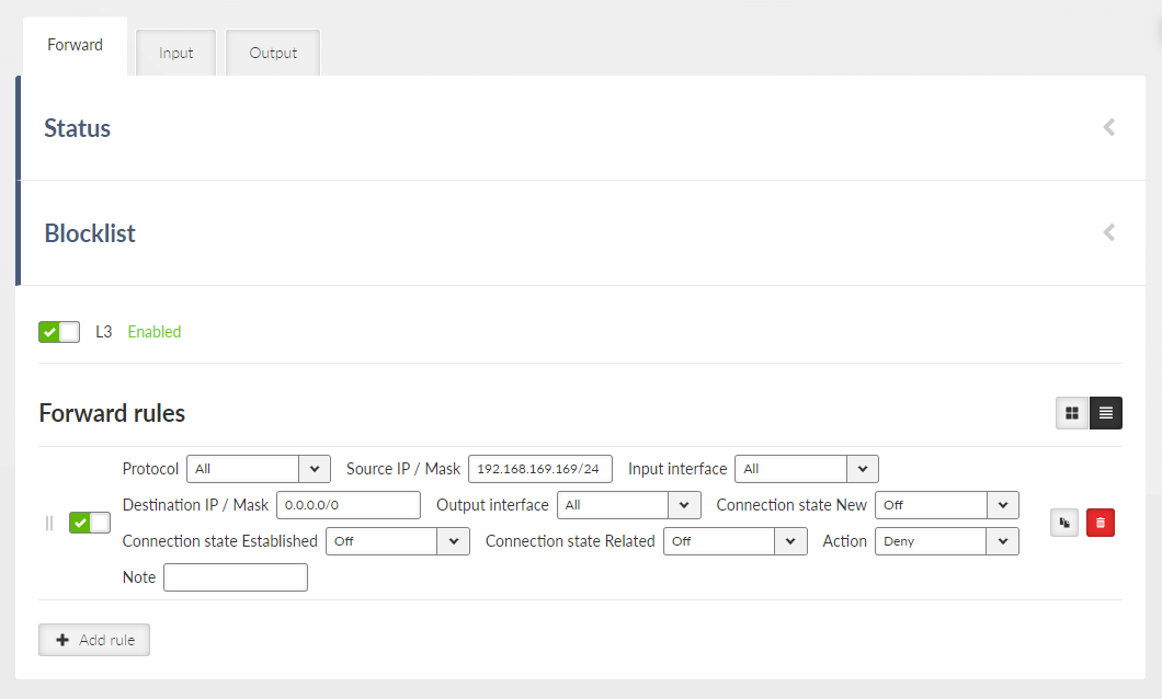
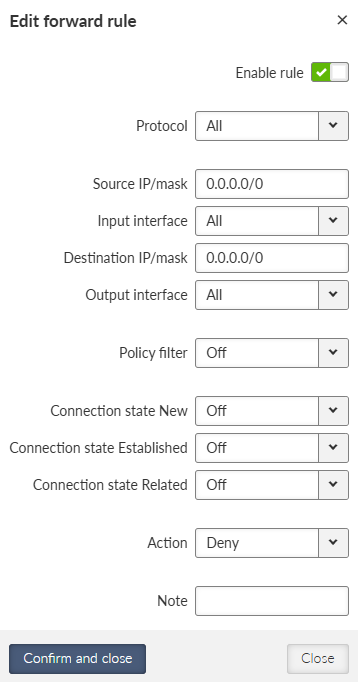
Each individual firewall rule is described by following parameters:
- Enable rule
Check box {On; Off}, default = “Off”
Enables / disables L3 firewall rule.
- Protocol
List box {All; ICMP; UDP; TCP; GRE; ESP; Other}, default = “All”
Select the transport protocol to filter by. The “All” option disables filtering by protocol.
- Protocol number
Number (1-255), default = 1
The transport protocol number by which it is filtered. This parameter occurs only when parameter Protocol is set to “Other”.
- Source IP / Mask
IP address, Mask, default = 0.0.0.0/0
Source IP address/Mask of the packet. If mask is set to 0, it is not filtered by source IP address.
The rule with narrower mask has higher priority. The rules order does affect priority.
- Source port (from) / Source port (to)
Number (0-65536), default = 0
Interval of source ports. This parameter occurs only when parameter Protocol is set either to “UDP” or “TCP”.
- Input interface
List box {All; WWAN; All ETH; EXT; ETH1..ETH5; All serial PPP; PPPoE client; GRE L2; GRE L3; OpenVPN L2; OpenVPN L3; Other}, default = “All”
Selects the input device (interface, port) from which the packet came.
- Input interface name
String (0-16 symbols), default = <empty>
The name of the input interface (or bridge port) of the packet.
This parameter occurs only when parameter Input interface is set to “Other”.
- Destination IP / Mask
IP address, Mask, default = 0.0.0.0/0
Destination IP address/Mask of the packet. If mask is set to 0, it is not filtered by destination IP address.
The rule with narrower mask has higher priority. The rules order does affect priority.
- Destination port (from) / Destination port (to)
Number (0-65536), default = 0
Interval of destination ports. This parameter occurs only when parameter Protocol is set either to “UDP” or “TCP”.
- Output interface
List box {All; WWAN; All ETH; EXT; All serial PPP; PPPoE client; GRE L3; OpenVPN L3; Other}, default = “All”
Selects the output interface from which the packet leaves. Cannot select the bridge port.
- Policy filter
List box {Off; On}, default = “Off”
Enables packet filtering according to the applied policy – IPsec.
- Direction
Listbox: {In (Decapsulation), Out (Encapsulation)}, default = “Out (Encapsulation)”
Filters by packet processing direction.
- Policy
Listbox: {None, IPsec}, default = “None”
Filters according to the policy applied to the packet:
None – The packet will not be processed by IPsec (decapsulation and encapsulation)
IPsec – The packet will be processed by IPsec
- Connection state New
List box {Off; On}, default = “Off”
Relates to the first packet when a TCP connection starts (Request from TCP client to TCP server for opening a new TCP connection). Used e.g. for allowing to open TCP only from M!DGE3 network to outside.
- Connection state Established
List box {Off; On}, default = “Off”
Relates to an already existing TCP connection. Used e.g. for allowing to get replies for TCP connections created from M!DGE3 network to outside.
- Connection state Related
List box {Off; On} default = “Off”
A connection related to the “Established” one, e.g. FTP typically uses 2 TCP connections control and data, where data connection is created automatically by using dynamic ports.
Note Management connection to a remote M!DGE3 may be lost, when another M!DGE3 acts as a router along the management packets path and TCP port 8889 (Remote Access) is disabled (DENY rule) in L3 firewall settings of that routing M!DGE3 (FORWARD chain).
- Action
List box {Deny; Allow}, default = “Deny”
Selects the action to perform on a packet that matches the configured filter.
Input rules in an L3 firewall regulate how IP packets destined for the router itself are handled. These rules determine whether traffic should be accepted or dropped based on factors like source IP address, protocol, and port number.
Packets coming from addresses on the Blocklist are automatically dropped. Addresses are added to the Blocklist as a result of an Input firewall rule with the Action set to “Deny, Add to Blocklist.”
Additionally, the system creates automatic Input rules based on interface settings:
Management access is limited on individual interfaces according to the “Allow unit management” setting for that interface.
Remote access is restricted on individual interfaces based on the “Allow Remote access” setting for that interface.
By configuring input rules and interface settings, administrators can ensure robust protection against unauthorized access and direct attacks targeting the device.
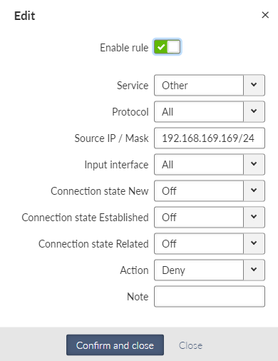
Each individual firewall rule is described by following parameters:
- Enable rule
Check box {On; Off}, default = “Off”
Enables / disables L3 firewall rule.
- Service
List box {Other; COM1; COM2; COM3; TS1; TS2; TS3; TS4; TS5; SSH; HTTP; HTTPS; Remote access; SNMP; NTP}, default = “Other”
Allows you to select a known service on the station whose protocol and destination port the rule filter will capture.
- Protocol
List box {All; ICMP; UDP; TCP; GRE; ESP; Other}, default = “All”
Select the transport protocol to filter by. The “All” option disables filtering by protocol.
- Protocol number
Number (1-255), default = 1
The transport protocol number by which it is filtered. This parameter occurs only when parameter Protocol is set to “Other”.
- Source IP / Mask
IP address, Mask, default = 0.0.0.0/0
Source IP address/Mask of the packet. If mask is set to 0, it is not filtered by source IP address.
The rule with narrower mask has higher priority. The rules order does affect priority.
- Source port (from) / Source port (to)
Number (0-65536), default = 0
Interval of source ports. This parameter occurs only when parameter Protocol is set either to “UDP” or “TCP”.
- Input interface
List box {All; WWAN; All ETH; EXT; ETH1..ETH5; All serial PPP; PPPoE client; GRE L2; GRE L3; OpenVPN L2; OpenVPN L3; Other}, default = “All”
Selects the input device (interface, port) from which the packet came.
- Input interface name
String (0-16 symbols), default = <empty>
The name of the input interface (or bridge port) of the packet.
This parameter occurs only when parameter Input interface is set to “Other”.
- Destination IP / Mask
IP address, Mask, default = 0.0.0.0/0
Destination IP address/Mask of the packet. If mask is set to 0, it is not filtered by destination IP address.
The rule with narrower mask has higher priority. The rules order does affect priority.
- Destination port (from) / Destination port (to)
Number (0-65536), default = 0
Interval of destination ports. This parameter occurs only when parameter Protocol is set either to “UDP” or “TCP”.
- Policy filter
List box {Off; On}, default = “Off”
Enables packet filtering according to the applied policy – IPsec.
- Policy
Listbox: {None, IPsec}, default = “None”
Filters according to the policy applied to the packet:
None – The packet will not be processed by IPsec (decapsulation)
IPsec – The packet will be processed by IPsec
- Connection state New
List box {Off; On}, default = “Off”
Relates to the first packet when a TCP connection starts (Request from TCP client to TCP server for opening a new TCP connection). Used e.g. for allowing to open TCP only from M!DGE3 network to outside.
- Connection state Established
List box {Off; On}, default = “Off”
Relates to an already existing TCP connection. Used e.g. for allowing to get replies for TCP connections created from M!DGE3 network to outside.
- Connection state Related
List box {Off; On} default = “Off”
A connection related to the “Established” one. e.g. FTP typically uses 2 TCP connections control and data, where data connection is created automatically by using dynamic ports.
Note Management connection to a remote M!DGE3 may be lost, when another M!DGE3 acts as a router along the management packets path and TCP port 8889 (Remote Access) is disabled (DENY rule) in L3 firewall settings of that routing M!DGE3 (FORWARD chain).
- Action
List box {Deny; Allow; Deny, Add to Blocklist}, default = “Deny”
Selects the action to perform on a packet that matches the configured filter.
Deny, Add to Blocklist – all traffic from the particular address will be automatically dropped. Blocklist has limited capacity of 512 addresses. Once its capacity is exceeded, the oldest address is overwritten. Addresses added to the blocklist remain in for one week (604,800s) and are deleted from it afterwards. Change of configuration including firewall, or unit reboot will delete those addresses as well.
Output rules in an L3 firewall govern how IP packets originating from the router itself are handled. These rules allow administrators to control traffic sent by the router, specifying whether it should be allowed or blocked based on factors such as destination IP address, protocol, and port number. By configuring output rules, administrators can restrict unnecessary or potentially harmful outbound traffic, enforce security policies, and manage communication initiated by the router.
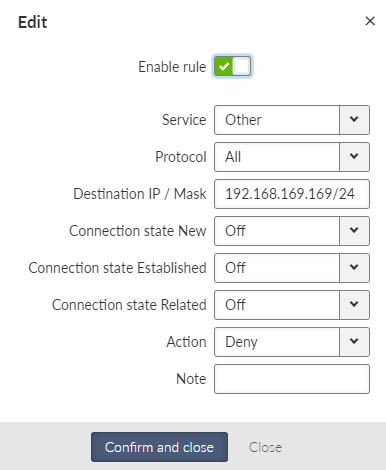
Each individual firewall rule is described by following parameters:
- Enable rule
Check box {On; Off}, default = “Off”
Enables / disables L3 firewall rule.
- Service
List box {Other; COM1; COM2; COM3; TS1; TS2; TS3; TS4; TS5; SSH; HTTP; HTTPS; Remote access; SNMP; NTP}, default = “Other”
Allows you to select a known service on the station whose protocol and destination port the rule filter will capture.
- Protocol
List box {All; ICMP; UDP; TCP; GRE; ESP; Other}, default = “All”
Select the transport protocol to filter by. The “All” option disables filtering by protocol.
- Protocol number
Number (1-255), default = 1
The transport protocol number by which it is filtered. This parameter occurs only when parameter Protocol is set to “Other”.
- Source IP / Mask
IP address, Mask, default = 0.0.0.0/0
Source IP address/Mask of the packet. If mask is set to 0, it is not filtered by source IP address.
The rule with narrower mask has higher priority. The rules order does affect priority.
- Source port (from) / Source port (to)
Number (0-65536), default = 0
Interval of source ports. This parameter occurs only when parameter Protocol is set either to “UDP” or “TCP”.
- Destination IP / Mask
IP address, Mask, default = 0.0.0.0/0
Destionation IP address/Mask of the packet. If mask is set to 0, it is not filtered by destination IP address.
The rule with narrower mask has higher priority. The rules order does affect priority.
- Destination port (from) / Destination port (to)
Number (0-65536), default = 0
Interval of destination ports. This parameter occurs only when parameter Protocol is set either to “UDP” or “TCP”.
- Output interface
List box {All; WWAN; All ETH; EXT; All serial PPP; PPPoE client; GRE L3; OpenVPN L3; Other}, default = “All”
Selects the output interface from which the packet leaves. Cannot select the bridge port.
- Output interface name
String (0-16 symbols), default = <empty>
The name of the output interface of the packet.
This parameter occurs only when parameter Input interface is set either to “Other”.
- Policy filter
List box {Off; On}, default = “Off”
Enables packet filtering according to the applied policy – IPsec.
- Policy
Listbox: {None, IPsec}, default = “None”
Filters according to the policy applied to the packet:
None – The packet will not be processed by IPsec (encapsulation)
IPsec – The packet will be processed by IPsec
- Connection state New
List box {Off; On}, default = “Off”
Relates to the first packet when a TCP connection starts (Request from TCP client to TCP server for opening a new TCP connection). Used e.g. for allowing to open TCP only from M!DGE3 network to outside.
- Connection state Established
List box {Off; On}, default = “Off”
Relates to an already existing TCP connection. Used e.g. for allowing to get replies for TCP connections created from M!DGE3 network to outside.
- Connection state Related
List box {Off; On} default = “Off”
A connection related to the “Established” one. e.g. FTP typically uses two TCP connections control and data, where data connection is created automatically by using dynamic ports.
Note Management connection to a remote M!DGE3 may be lost, when another M!DGE3 acts as a router along the management packets path and TCP port 8889 (Remote Access) is disabled (DENY rule) in L3 firewall settings of that routing M!DGE3 (FORWARD chain).
- Action
List box {Deny; Allow}, default = “Deny”
Selects the action to perform on a packet that matches the configured filter.
Network address and port translation (NAPT) is a method of mapping an IP address (or port) space into another by modifying network address information in the IP header of packets while they are in transit across a traffic routing device.
Source Network Address Translation (SNAT) – rewrites the source address and/or port within the leaving connection and performs opposite changes for returning packets.
SNAT:
Allows to pretend, that the packets come from a device, that performs SNAT.
Performs during packet output from a device (after routing and filtering in firewall).
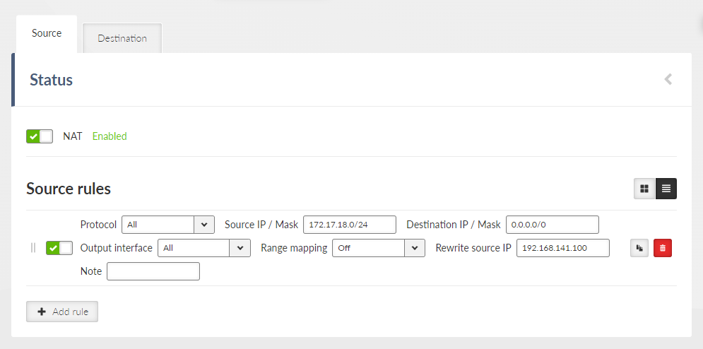
Parameters “Protocol”, “Source IP / Mask”, “Destination IP / Mask”, “Output Interface”,“Source port from”, “Source port to”, “Destination port from”, “Destination port to” and “Protocol number” define a filter, which is capturing specified packets. SNAT rule applies for those packets.
Parameters “Source port from”, “Source port to”, “Destination port from” and “Destination port to” occur only if parameter “Protocol” is set to “UDP” or “TCP”.
Parameter “Protocol number” occurs only if parameter “Protocol” is set to “Other”.
Each individual NAT rule is described by following parameters:
- Enable rule
List box {Enable; Disable}, default = “Disable”
Enables / disables all Source NAT rules.
- Protocol
List box {All; ICMP; UDP; TCP; GRE; ESP; Other}, default = “All”
Filters selected protocol. If none of the mentioned values suits, select “Other”.
- Protocol number
Number {0 – 255}, default = 1
This parameter occurs only, if parameter “Protocol” is set to “Other”.
- Source IP / Mask
IP address, default = 0.0.0.0/0
Defines the source IP subnet.
- Source port (from) / Source port (to)
Number {0 – 65535}, default = 0
Defines the range of values of source port. Value 0 means, that it is not filtered according to the source port. If only one port is required, set both parameters to the same number. These parameters occur only, if parameter “Procotol” is set to “UDP” or “TCP”.
- Destination IP / Mask
IP address, default = 0.0.0.0/0
Defines the destination IP subnet.
- Destination port (from) / Destination port (to)
Number {0 – 65535}, default = 0
Defines the range of values of destination port. Value 0 means, that it is not filtered according to the destination port. These parameters occur only, if parameter “Procotol” is set to “UDP” or “TCP”.
- Output Interface
List box {All; ; ;WWANAll ETH; EXT; GRE L3; Other}, default = “All”
Filters selected interfaces.
- Output interface name
Has to be set as one of existing interfaces (the name of LAN (or VLAN) interface, the name of GRE tunnel, etc.). This parameter occurs only, if parameter “Output Interface” is set to “Other”.
- Range mapping
List box {Off; IP address to IP address}, default = “Off”
Off – Source address and (or) port will be replaced by values from parameters “Rewrite source IP” and “Rewrite source port”. This applies only if those parameters are set (they are not set as 0.0.0.0).
IP address to IP address (NETMAP) – Rewriting the Range mapping of source IP address. New source address will contain prefix from parameters “Rewrite Source IP” and “Rewrite Source IP / Mask”. Rest of the source address will be filled by the original source address.
- Rewrite source IP
IP address, default = 0.0.0.0/0
Defines a new source address. Value 0.0.0.0/0 means, that the source address is not changed.
- Rewrite source port
Number {0 – 65535}, default = 0
Defines a new source port (rewriting multiple defined ports into one). Value 0 means, that the source port is not changed.
- Note
Optional comment.
Destination Network Address Translation (DNAT) – rewrites the destination address and/or port within incoming connection and performs opposite changes for returning packets.
DNAT:
Allows to redirect connection destination to a device, that performs DNAT.
Performs during packet input to a device (before redirecting and filtering in firewall).
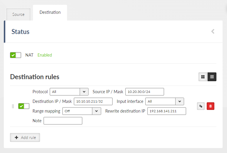
Parameters “Protocol”, “Source IP / Mask”, “Destination IP / Mask”, “Output Interface”,“Source port from”, “Source port to”, “Destination port from”, “Destination port to” and “Protocol number” define a filter, which is catching specified packets. SNAT rule applies for those packets.
Parameters “Source port from”, “Source port to”, “Destination port from” and “Destination port to” occur only if parameter “Protocol” is set to “UDP” or “TCP”.
Parameter “Protocol number” occurs only if parameter “Protocol” is set to “Other”.
Each individual NAT rule is described by following parameters:
- Enable rule
List box {Enable; Disable}, default = “Disable”
Enables / disables all Destination NAT rules.
- Protocol
List box {All; ICMP; UDP; TCP; GRE; ESP; Other}, default = “All”
Filters selected protocol. If none of the mentioned values suits, select “Other”.
- Protocol number
Number {0 – 255}, default = 1
This parameter occurs only, if parameter “Protocol” is set to “Other”.
- Source IP / Mask
IP address, default = 0.0.0.0/0
Defines the source IP subnet.
- Source port (from) / Source port (to)
Number {0 – 65535}, default = 0
Defines the range of values of source port. Value 0 means, that it is not filtered according to the source port. If only one port is required, set both parameters on the same number. These parameters occur only, if parameter “Procotol” is set to “UDP” or “TCP”.
- Destination IP / Mask
IP address, default = 0.0.0.0/0
Defines the destination IP subnet.
- Destination port (from) / Destination port (to)
Defines the range of values of destination port. Value 0 means, that it is not filtered according to the destination port. These parameters occur only, if parameter “Procotol” is set to “UDP” or “TCP”.
- Input interface
List box {All; WWAN; All ETH; EXT; GRE3; Other}, default = “All”
Filters selected interfaces.
- Input interface name
Has to be set as one of existing interfaces (the name of LAN (or VLAN) interface, the name of GRE tunnel, etc.). This parameter occurs only, if parameter “Input Interface” is set to “Other”.
- Range mapping
List box {Off; IP address to IP address}, default = “Off”
Off – Destination address and (or) port will be replaced by values from parameters “Rewrite destination IP” and “Rewrite destination port”. This will apply only if those parameters are set (they are not set as 0.0.0.0).
IP address to IP address (NETMAP) – Rewriting the Range mapping of source IP address. New source address will contain prefix from parameters “Rewrite Source IP” and “Rewrite Source IP / Mask”. Rest of the source address will be filled by the original source address.
Port to IP address (PORTMAP): Range mapping of destination ports (parameters “Destination port from”, “Destination port to”). New range mapping of destination ports origins in parameter “Rewrite destination IP”. It can be additionally overwritten to parameter “Rewrite destination port”.
Explanation of non-typical and interesting parameters:
- Destination port (from) and Destination port (to)
DNAT rule applies to UDP data with destination ports within the 20001-20015 range only
- Input interface
Data must be received on any ETH port
- Range mapping
Set to “Port to IP address” – i.e., destination ports change the destination IP address(es) accordingly.
- Rewrite destination IP and Rewrite destination port
Set to IP 10.10.10.1 and port 502 – resulting in a range of IPs 10.10.10.1 – 10.10.10.15 due to Destination ports of received UDP data in a range of 20001-20015 (15 ports = 15 IP addresses). A new port is always 20000 (i.e., DNP3 default port).
- Rewrite destination IP
IP address, default = 0.0.0.0/0
Defines a new destination address. Value 0.0.0.0/0 means, that the destination address is not changed.
- Rewrite destination port
Number {0 – 65535}, default = 0
Defines a new destination port (rewriting multiple defined ports into one). Value 0 means, that the destination port is not changed.
- Note
Optional comment.
| Note | |
|---|---|
FTP connection is a special type of TCP with multiple sessions being opened and internal functionality. If you configure DNAT for the connected FTP server, enable the “FTP connection tracker” parameter and specify a correct port (default is 21). These parameters can only be set in the Advanced menu. |
MASQUERADE rule for Cellular connection has lower priority that user NAT (it is tested after the NAT), thus it is possible to create exceptions in NAT settings.
By using DNAT it is possible to intercept a passing connection and redirect it into the M!DGE3 (similar to a proxy behavior).
For redirection
Local IP address will be filled into “Rewrite destination IP” parameter.
Service port, to which is the local address being redirected will be filled into “Rewrite destination port” parameter.
NAT and IPsec
DNAT can be used before packing a packet into the IPsec. For more information see Section 7.4.1.3.3, “Interaction with DNAT”.
SNAT works on packets unpacked from IPsec.
SNAT can be used before packing a packet into the IPsec (parameter “Output interface” must be set to “All”)
Rules of SNAT and MASQUERADE (from Cellular) changes packets addresses before capturing by IPsec traffic selector.
VPN (Virtual Private Network) extends a private network across a public network, and enables users to send and receive data across shared or public networks as if their computing devices were directly connected to the private network. Applications running across the VPN may therefore benefit from the functionality, security, and management of the private network.
Internet Protocol Security (IPsec) is a network protocol suite that authenticates and encrypts the packets of data sent over a network. IPsec includes protocols for establishing mutual authentication between agents at the beginning of the session and negotiation of cryptographic keys for use during the session. IPsec uses cryptographic security services to protect communications over Internet Protocol (IP) networks. IPsec supports network-level peer authentication, data-origin authentication, data integrity, data confidentiality (encryption), and replay protection. IPsec is an end-to-end security scheme operating within the Internet Layer of the Internet Protocol Suite. IPsec is recognized as a secure, standardized and well-proven solution by the professional public.
There are 2 modes of operation, M!DGE3 offers both the Tunnel mode and the Transport mode. In Tunnel mode, the entire IP packet is encrypted and authenticated. It is then encapsulated into a new IP packet (ESP – Encapsulating Security Payloads) with a new IP header. In Transport mode, only the payload of the original IP packet is encrypted and authenticated. The original IP header remains intact, allowing for direct routing, while the data itself is secured using AH or ESP protocols.
Symmetrical cryptography is used to encrypt the packets. The symmetric keys must be safely delivered to the peer. In order to maintain a secure connection, symmetric keys must be regularly exchanged. The protocol used for secure key exchange is IKE (Internet Key Exchange). Both IKE version 1 and the newer version 2 are available in M!DGE3.
IKE protocol communication with the peer is established using UDP frames on port 500. However, if NAT-T (NAT Traversal) or MOBIKE (MOBile IKE) are active, the UDP port 4500 is used instead.
| Note | |
|---|---|
NAT-T is automatically recognized by IPsec implementation in M!DGE3. |
The IPsec tunnel is provided by Security Association (SA). There are 2 types of SA:
IKE SA: IKE Security Association providing SA keys exchange with the peer.
CHILD SA: IPsec Security Association providing packet encryption.
Every IPsec tunnel contains 1 IKE SA and at least 1 CHILD SA. In M!DGE3 can be set maximum of 24 IKE_SA and 48 CHILD_SA (TS).
Link partner (peer) secure authentication is assured using Pre-Shared Key (PSK) authentication method: Both link partners share the same key (passphrase).
As and when the CHILD SA expires, new keys are generated and exchanged using IKE SA.
As and when the IKE SA version IKEv1 expires – new authentication and key exchange occurs and a new IKE SA is created. Any CHILD SA belonging to this IKE SA is re-created as well.
As and when the IKE SA version IKEv2 expires one of two different scenarios might occur:
If the re-authentication is required – the behavior is similar to IKEv1 (see above).
It the re-authentication is not required – only new IKE SA keys are generated and exchanged.
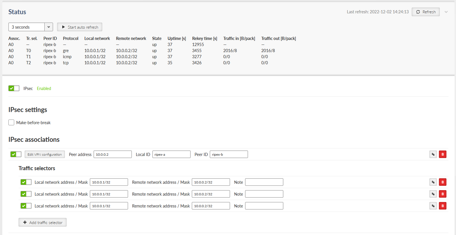
- IPsec
{Enable; Disable}, default = “Disable”
IPsec system turning On/Off
There can be a maximum of 16 active CHILD SA (in total over all Active IKE SA).
Every “Active” line must have an equivalent on the peer side with reversed “Local network…” and “Remote network…” fields.
“Local network…” and “Remote network…” fields must contain different address ranges and must not interfere with the USB service connection (10.9.8.7/28) or internal connection to FPGA (192.0.2.233/30).
Each “Active” Traffic selector in the configuration table must be unique.
- Make-before-break
{On; Off}, default = “Off”
This parameter is valid for all IKE SA using IKEv2 with re-authentication. A temporary connection breaks during IKE_SA re-authentication is suppressed by this parameter. This function may not operate correctly with some IPsec implementations (on peer side).
To further configure IPsec VPN tunnel, click the Add VPN configuration button.
- Operation mode
List box {Tunnel; Transport}, default = “Tunnel”
Selects IPsec mode
Note The Tunnel mode is usually used for site-to-site and host-to-site connections. The Transport mode is used for host-to-host connection and very often combined with GRE and dynamic routing.
- Add / Edit IPsec VPN tunnel associations
Every item in the table represents one IKE SA. There can be a maximum of 24 active IKE SA (limited by system resources).
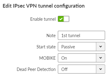
- Local address
IP address, default = “0.0.0.0”
IP address used as the source address for IKE negotiation. If specified, must be a valid local address.
When left at 0.0.0.0 the Local address becomes dynamic.
- Peer address
IP address, default = “0.0.0.0”
IP address of the peer running the IKE daemon that will be negotiated with. It must not be the same as Local address.
- Local ID
IP address or FQDN (Fully Qualified Domain Name), default = “Local-0”
IP address or FQDN used as the Local side identification. It must be the same as “Peer ID” of the IKE peer.
- Peer ID
IP address or FQDN (Fully Qualified Domain Name), default = “Peer-0”
IP address or FQDN used as the IKE peer identification. It must be the same as “Local ID” of the IKE peer. The “Peer ID” must be unique in the whole table.
- Start state
List box {Passive; On demand; Start}, default = “Passive”
Passive – the connection is not established, it is waiting for the other side.
On Demand – The connection will start to establish when a packet tries to pass through it.
Start – the connection is established immediately.
- MOBIKE
List box {On; Off}, default = “On”
Enables MOBIKE for IKEv2 supporting mobility or migration of the tunnels. Please note IKE is moved from port 500 to port 4500 when MOBIKE is enabled. The peer configuration must match.
It is strongly recommended to use MOBIKE mode in case of routing the traffic over the Cellular interface.
- Dead Peer Detection
List box {On; Off}, default = “Off”
Detection of lost connection with the peer. IKE test packets are sent periodically. When packets are not acknowledged after several attempts, the connection is closed (corresponding actions are initialized). In the case when Detection is not enabled, a connection loss is discovered when regular key exchange process is initiated.
- DPD period [s]
Number {5 – 28800}, default = 30
Dead Peer Detection check period.
This parameter is available only if parameter Dead Peer Detection is set to “On”.
- DPD action
List box {Clear; Hold; Restart}, default = “Hold”
One of three connection states automatically activated when connection loss is detected:
Clear – connection is closed and waiting
Hold – connection is closed. Connection is established when first packet transmission through tunnel is attempted.
Restart – connection is established immediately
This parameter is available only if parameter Dead Peer Detection is set to “On”.
- Management mode
List box {Off; Master; Slave}, default = “Off”
Selects how to manage the IPsec association.
Master – Managed by the Link Manager. Defines the Traffic selector of the tunnel.
Slave – Managed by the Link Manager. Takes over Traffic selectors from the Master Association.
This parameter is available only if parameter Link management is set to “On”.
- Phase 1 IKE
Parameters related to IKE SA (IKE Security Association) provide SA keys exchange with the peer.
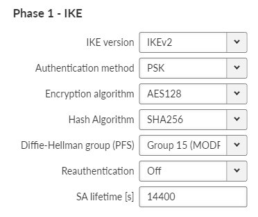
- IKE version
List box {IKEv2, IKEv1}, default = “IKEv2”
IKE version selection.
Must match the settings on the peer.
- IKE Authentication method
List box {PSK}, default = “PSK”
Peer authentication method. Peer configuration must match.
The “main mode” negotiation is the only option supported. The “aggressive mode” is not supported; it is recognized as unsafe when combined with PSK type of authentication.
- IKE Encryption algorithm
List box {3DES (legacy); AES128; AES192; AES256; AES128CCM (AEAD); AES192CCM (AEAD); AES256CCM (AEAD); AES128GCM (AEAD); AES192GCM (AEAD); AES256GCM (AEAD); ChaCha20Poly1305 (AEAD)}, default = “AES128”
IKE SA encryption algorithm. The “legacy” marked methods are recognized as unsafe. Peer configuration must match.
- IKE Integrity Algorithm
List box {MD5 (legacy); SHA1 (legacy); SHA256; SHA384; SHA512}, default = “SHA256”
IKE SA integrity algorithm. The “legacy” marked methods are recognized as unsafe. Peer configuration must match.
- IKE Diffie-Hellman group (PFS)
List box {None (legacy); Group 2 (MODP1024, legacy); Group 5 (MODP1536, legacy); Group 14 (MODP2048); Group 15 (MODP3072); Group 25 (ECP192); Group 26 (ECP224); Group 19 (ECP256); Group 20 (ECP384); Group 21 (ECP521); Group 27 (ECP224BP); Group 28 (ECP256BP); Group 29 (ECP384BP); Group 30 (ECP512BP); Group 31 (X25519); Group 32 (X448)}, default = “Group 15 (MODP3072)”
The PFS (Perfect Forward Secrecy) feature is performed using the Diffie-Hellman group method.
PFS increases IKE SA key exchange security. The “legacy” marked methods are recognized as unsafe. Peer configuration must match.
The higher the Diffie-Hellman group, the higher the security but also the higher the network and CPU load.
- IKE Reauthentication
List box {On; Off}, default = “Off”
This parameter is valid if IKEv2 is used. It determines the next action after IKE SA has expired. When enabled: the new IKE SA is negotiated including new peer authentication. When disabled: only the new keys are exchanged.
- IKE SA lifetime [s]
Number {180 – 86400}, default = 14400 s (4 hours)
Time of SA validity. The new key exchange or re-authentication is triggered immediately the key expires. The true time of expiration is randomly selected within the range of 90-110%.
Unfortunately, the more frequent the key exchange, the higher the network and CPU load.
Note If low capacity channel is used, the M!DGE3’s channel load can affected during the key exchange process.
- IKE Post-quantum PSK (PPK)
List box {On; Off}, default = “Off”
Enables additional protection using PPK when using IKEv2.
- IKE PPK ID
String {0–64 char}, default = <empty>
PPK key identifier, which can be an FQDN. It must not be empty or the same as the identifier in another IKE SA. It is used to identify and select the PPK key between peers, and they must have the same identifier.
- IKE PPK KEY ID
List box {None; Radio Encryption Key}, default = “None”
Key identifier in the keyring. The key must exist and be populated with the type ‘psk’ and a length of at least 32B (256 bits).
- Phase 2 – IPsec
Certain parameters are shared by all subordinate CHILD SA. IPsec Security Association provides packet encryption (user traffic encryption).
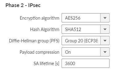
- Encryption algorithm
List box {3DES (legacy); AES128; AES192; AES256}, default = “AES128”
IKE CHILD SA encryption algorithm. The “legacy” marked methods are recognized as unsafe. Peer configuration must match.
- IPsec Integrity algorithm
List box {MD5 (legacy); SHA1 (legacy); SHA256; SHA384; SHA512}, default = “SHA256”
IKE CHILD SA integrity algorithm. The “legacy” marked methods are recognized as unsafe. Peer configuration must match.
- IPsec Diffie-Hellman group (PFS)
List box {None (legacy); Group 2 (MODP1024, legacy); Group 5 (MODP1536, legacy); Group 14 (MODP2048); Group 15 (MODP3072); Group 25 (ECP192); Group 26 (ECP224), Group 19 (ECP256); Group 20 (ECP384); Group 21 (ECP521); Group 27 (ECP224BP); Group 28 (ECP256BP); Group 29 (ECP384BP); Group 30 (ECP512BP); Group 31 (X25519); Group 32 (X448)}, default = “Group 15 (MODP3072)”
The PFS (Perfect Forward Secrecy) feature is performed using the Diffie-Hellman group method.
PFS increases IKE CHILD SA key exchange security. The “legacy” marked methods are recognized as unsafe. Peer configuration must match.
The higher the Diffie-Hellman group, the higher the security but also the higher the network and CPU load.
- Payload compression
List box {On; Off}, default = “Off”
This parameter enables payload compression. This takes place before encryption. Peer configuration must match.
- IPsec SA lifetime [s]
Number {180 – 86400}, default = 3600
Time of CHILD SA validity. The new key exchange or re-authentication is triggered immediately the key expires. The true time of expiration is randomly selected within the range of 90-110%.
The SA lifetime for CHILD SA is normally much shorter than SA lifetime for IKE SA because the CHILD SA normally transfers much more data than IKE SA (key exchange only). Changing the keys serves as protection against breaking the cypher by analyzing big amounts of data encrypted by the same cypher.
Note If low capacity channel is used, the M!DGE3’s channel load can affected during the key exchange process.
- PSK
PSK (Pre-shared key) authentication is used for IKE SA authentication. The relevant peer is identified using it’s “Peer ID”. The key must be the same for both local and peer side of the IPsec.
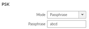
- Mode
List box {Passphrase; Key ID}, default = “Passphrase”
- Passphrase
The PSK key is entered as a passphrase. An empty passphrase is not allowed (max. length is 128 characters). Passphrase for the FW version 2.1.1.0 must not contain any unsupported characters. Unsupported characters are: “, `, \, $, ;. The full UTF-8 character set is available since FW 2.1.2.0.
Note If the passphrase starts with the characters 0x or 0s, then the connection between M!DGE3 with FW 2.1.2.0 (and newer) and M!DGE3 with FW 2.1.1.0 (and older) will not be established. Likewise, any other device that writes the passphrase into its configuration as a plain string (not ‘hexa’ or ‘base64’ encoded).
- Key
It is possible to set 256 bits long Key instead of Passphrase. This parameter occurs only, if parameter Mode is set to “Key”.
Defines which traffic is forwarded to the IPsec tunnel. The rule that defines this selection matches an incoming packet to “Local network …” and “Remote network …” address ranges.
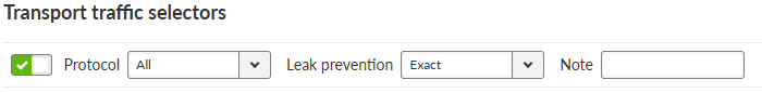

- Local network address / Mask
IP address/Mask, default = “0.0.0.0/32”
Source IP address and mask of the packets to be captured and forwarded to the encrypted tunnel.
- Remote network address / Mask
IP address/Mask, default = “0.0.0.0/32”
Destination IP address and mask of the packets to be captured and forwarded to the encrypted tunnel.
- Protocol
List box {All; ICMP; UDP; TCP; GRE; ESP; Other}, default = “All”
Defines the transport protocol of packets which will be caught and encrypted.
- Protocol number
Number {1 – 255}, default = 1
Defines the number of the transport protocol of packets which will be caught and encrypted. This parameter is available only if parameter Protocol is set to “Other”.
- Leak prevention
List box {Off; Exact; Paranoid}, default = “Exact”
The level of automatic protection against leaking or receiving unencrypted traffic.
Off – No automatic protection rules. The user must write his own in the L3 firewall.
Exact – Automatic rules exactly copy the CHILD SA settings.
Paranoid – For input/forward rules it’s the same as Exact. For output, the automatic rules are stricter because they do not filter by the source address of the packet.
For Tunnel mode, a special IPsec routing table is created to correctly fill in the source IP address of packets sent from the unit over IPsec.
For each traffic selector (CHILD SA), the service tries to find a local IP address that matches the address and mask of the local part of the selector. If such an address exists, an auxiliary routing rule is created in the IPsec table that has the address and mask of the remote part of the selector as the destination and the found local address as the local preferred source address. With this rule, the locally generated packets will have addresses that match the CHILD SA selector and will be encrypted.
At the same time, the existence of a routing rule for the packet is ensured. If the routing rule did not exist, the packet would be dropped before being captured and encrypted by IPSec.
| Note | |
|---|---|
If the selector is limited to a specific protocol, however, a routing rule will not be created because it would cover all protocols, including traffic that the selector does not capture. |
User routing is required for Transport mode; without it, the IKE SA association could not be established. This mode does not use the special IPsec routing table.
A user-defined firewall filters packets before or after encryption in IPsec. If automatic protection against leakage of unencrypted traffic is disabled, custom protection rules (Policy filter) can be applied.
- Handwritten protection rules must prevent
Sending traffic to be encrypted as unencrypted (data leakage).
Receiving unencrypted traffic that should have been encrypted (data insertion).
- Tunnel mode
INPUT – For each traffic selector (CHILD SA) a rule discarding traffic with Policy “None” and with swapped address ranges.
OUTPUT – For each traffic selector (CHILD SA) a rule discarding traffic with Policy “None” and with the same address ranges.
FORWARD – For each traffic selector (CHILD SA) 2 rules:
Discarding traffic with Policy “None” and Direction “Out (Encapsulation)” and with the same address ranges.
Discarding traffic with Policy “None” and Direction “In (Decapsulation)” and with swapped address ranges.
- Transport mode
INPUT – For each traffic selector (CHILD SA), a rule to discard traffic with a Policy set to “None” and with a source address of the IPsec peer address and a destination address of the IPsec local address.
OUTPUT – For each traffic selector (CHILD SA), a rule to discard traffic with a Policy set to “None” and with a source address of the IPsec local address and a destination address of the IPsec peer address.
If IPsec captures packets which were modified by DNAT, routing rules automatically created by IPsec rules will not apply to them, because DNAT rewrites their destination address. Therefore a new static routing rule must be created (SETTINGS > Routing > Static) for those packets.
GRE L2 tunnel is interconnected to the bridge (LAN interface) as one of the bridge’s port, it captures Ethernet frames of the bridge and sends them to the other end of the tunnel. It enables to build bridge via the complex network and combine the local partial networks to one network.
GRE L2 tunnel can be used to tunnel the Q-in-Q and IPv6 traffic over the M!DGE3 IPv4 network.
- GRE L2 Enable
Switches all L2 tunnels On or Off.
Individual L2 tunnels:
- Enable
Enables particular L2 tunnel. Maximum number of configurable tunnels is 256.
- Tunnel name
The base of the tunnel interface name, prefixed with “gre_”.
- Peer address
IP address of the equipment with the second end of the tunnel. This address is the expected source address of incoming GRE packets from the peer.
- Interface
Has to be set as one of existing bridge’s name in SETTING/Interfaces/Ethernet/ Network interface Name.
- MTU [B]
MTU of the L2 tunnel. Number {74 – 1500}, default = 1430 B
Overhead of the L2 tunnel is 38 B, so it should be GRE MTU = Path MTU – 38.
Minimum MTU value to establish TCP between M!DGE3 units = 576 B.
Note For traffic in bridged network (e.g. when using Transparent protocol), it is necessary to set the MTU to a proper value, otherwise there is a risk of packet fragmentation and thus compromising efficiency and reliability of the transfer.
- Key enabled
Enables using key identification of the tunnel from/to the same peer.
- Key
Identification number of the tunnel Number {0 – 4,294,967,295}, default = 0
- Note
Optional comment.
GRE L3 tunnel works as an additional unit’s interface with its own IP address (and mask). The routing rules are used for sending packets to this interface. It bridges part of the network, so it seems to be one hop for the user traffic.
- GRE L3 Enable
Switches all L3 tunnels On or Off.
Individual L3 tunnels:
- Enable
Enables particular L3 tunnel. Maximum number of configurable tunnels is 256.
- Tunnel name
The base of the tunnel interface name, prefixed with “gre_”.
- Peer address
IP address of the equipment with the second end of the tunnel. This address is the expected source address of incoming GRE packets from the peer.
- Tunnel address / Mask
IP address and mask of the GRE tunnel interface
- MTU
MTU of the L2 tunnel. Number {70 – 1476}, default = 1476
Overhead of the L3 tunnel is 24 B, so it should be GRE MTU = Path MTU – 24. If the MTU is bigger than is allowed along the route, the GRE packets will be discarded and ICMP report will be send back to the source of the original packet (Path MTU discovery).
Minimum MTU value to establish TCP between M!DGE3 units = 576 B.
- Key enabled
Enables using key identification of the tunnel from/to the same peer.
- Key
Identification number of the tunnel Number {0 – 4,294,967,295}, default = 0
- Allow unit management
Allows / disables unit management via GRE tunnel.
- Note
Optional comment.
OpenVPN is a virtual private network (VPN) system that allows to create secure encrypted point-to-multipoint connections in routed (TUN) or bridged (TAP) modes. Up to four instances (clients and/or servers) can be used simultaneously in one unit. Each server is capable of establishing connections with several tens of clients.
OpenVPN allows peers to authenticate to each other using pre-shared secret keys and certificates. An OpenVPN server is capable to release an authentication certificate for every client, using signatures and certificate authority (certificates can be generated / uploaded in the SETTINGS>Security>Credentials menu).
A time synchronisation of individual units is required for proper OpenVPN function.
Link for OpenVPN application note.
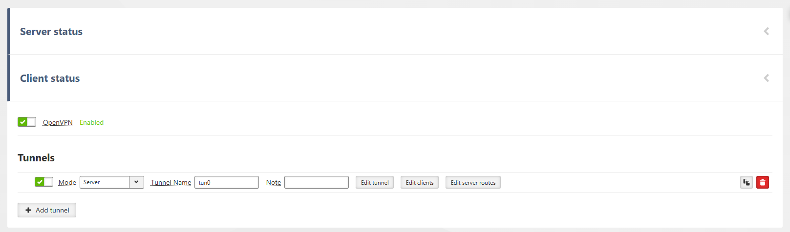
- OpenVPN Enable
List box {Off; On}, default = “Off”
Turns on the entire OpenVPN system.
- OpenVPN Tunnel Enable
List box {Off; On}, default = “On”
Enables / disables a particular OpenVPN tunnel.
- Mode
List box {Client; Server}, default = “Client”
Instance mode selection.
Server: Server passively listens and waits for client connections (one or more), then assigns addresses and sets up routing.
Client: Client actively connects to the server and retrieves part of the configuration.
- Tunnel name
String, default = “tun0”
String matching regular expression ‘^[a-zA-Z0-9_-]{1,10}$’. User part of the OpenVPN tunnel interface name, prefixed with ‘ovpn_’. Must be unique among active OpenVPN instances.
- Note
Optional comment.
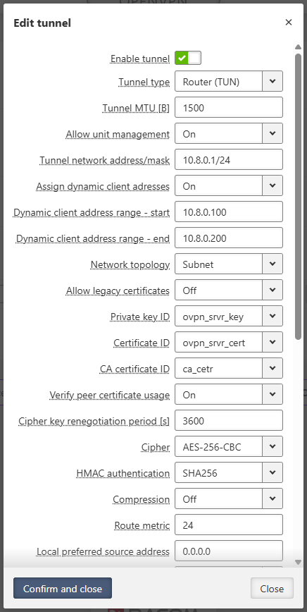
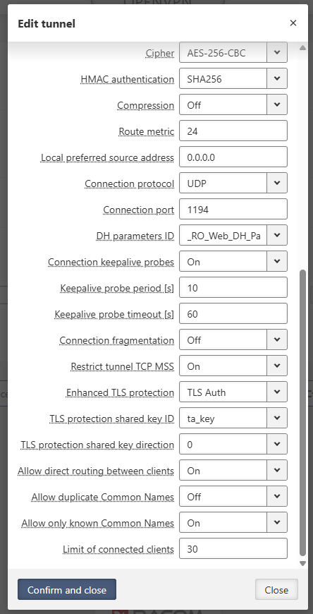
- Enable tunnel
List box {Off; On}, default = “On”
Enables / disables OpenVPN tunnel.
- Tunnel type
List box {Bridge, Router}, default = “Router”
Tunnel interface type selection.
Bridge: L2 interface (TAP) without its own address, connects as a port into a bridge (from Ethernet interfaces table).
Router: L3 interface (TUN) with its own IP address, routed using routing rules.
- Tunnel MTU [B]
Number {100 – 1500}, default = “1500”
MTU size on the tunnel interface.
Must be consistent on all ends (server and all clients). The server can override client settings, but correct MTU setup on clients is important for consistency.
- Network interface
List box {user defined bridge IDs}, default = “bridge”
Select your bridge interface. Your tunnel connects as a port into this bridge from your LAN interfaces table.
Only in Bridge (TAP)
- Allow unit management
List box {On, Off}, default = “On”
Permit administration access to your station through your tunnel interface.
Only in Router (TUN)
- Tunnel network address/mask
IP address and mask [16 – 29], default = “0.0.0.0/24”
Defines your address range on the tunnel interface. Your server receives the first unicast address in this range. The system assigns addresses from this range to your clients and sends the same mask for subnet topology.
Only in Router (TUN)
- Assign dynamic client addresses
List box {On, Off}, default = “Off”
Turns on dynamic address allocation for your clients without a static address. Your server attempts to maintain persistent address allocation for your client via the Common Name on their certificate.
Only in Router (TUN)
- Dynamic client address range – start
IP address, default = “0.0.0.100”
Defines your IP address range start for dynamic client allocation. This address must fall within your Tunnel network address/mask range. This start address must be less than or equal to your end address.
Only in Router (TUN)
- Dynamic client address range – end
IP address, default = “0.0.0.200”
Defines your IP address range end for dynamic client allocation. This address must fall within your Tunnel network address/mask range. This end address must be greater than or equal to your start address.
Only in Router (TUN)
- Network topology
List box {Subnet, Net30}, default = “Subnet”
Selects your network topology for address distribution.
Subnet: Assigns one address from the range to your clients and server.
Net30: Provides backward compatibility. Assigns a /30 subrange of 4 addresses to each participant. The two middle unicast addresses serve as the local and peer tunnel addresses.
Only in Router (TUN)
- Allow legacy certificates
List box {On, Off}, default = “Off”
Allows certificates signed with weak algorithms like SHA1. OpenVPN rejects these certificates by default. Using weak signature certificates compromises your network security.
- Private key ID
Keyring identifier
Choose your instance private key. The key must exist in your keyring with the Certificate key (PRI).
- Certificate ID
Keyring identifier
Choose your instance certificate. The key must exist in your keyring with the Certificate (PUB). The fingerprint of the contained public key must match its private key.
- CA certificate ID
Keyring identifier
Choose your Certificate Authority certificate. The key must exist in your keyring with the Certificate (PUB) or CA chain (PUB). This authority signs all participant certificates.
- Verify peer certificate usage
List box {On, Off}, default = “On”
Strictly check the Extended Key Usage attribute on peer certificates. This prevents your clients from impersonating your server. Clients check server certificates for TLS Web Server Authentication. Servers check client certificates for TLS Web Client Authentication.
- Cipher key renegotiation period [s]
Number [60, 86400], default = “3600”
Sets your data encryption key renegotiation period in seconds. The system uses the shorter period if your client and server settings differ. The system accepts the expired key for an equal duration from the start of renegotiation to maintain smooth traffic.
- Cipher
List box {Default, AES-128-CBC, AES-128-CFB, AES-128-CFB1, AES-128-CFB8, AES-128-GCM, AES-128-OFB, AES-192-CBC, AES-192-CFB, AES-192-CFB1, AES-192-CFB8, AES-192-GCM, AES-192-OFB, AES-256-CBC, AES-256-CFB, AES-256-CFB1, AES-256-CFB8, AES-256-GCM, AES-256-OFB, ARIA-128-CBC, ARIA-128-CFB, ARIA-128-CFB1, ARIA-128-CFB8, ARIA-128-GCM, ARIA-128-OFB, ARIA-192-CBC, ARIA-192-CFB, ARIA-192-CFB1, ARIA-192-CFB8, ARIA-192-GCM, ARIA-192-OFB, ARIA-256-CBC, ARIA-256-CFB, ARIA-256-CFB1, ARIA-256-CFB8, ARIA-256-GCM, ARIA-256-OFB, CAMELLIA-128-CBC, CAMELLIA-128-CFB, CAMELLIA-128-CFB1, CAMELLIA-128-CFB8, CAMELLIA-128-OFB, CAMELLIA-192-CBC, CAMELLIA-192-CFB, CAMELLIA-192-CFB1, CAMELLIA-192-CFB8, CAMELLIA-192-OFB, CAMELLIA-256-CBC, CAMELLIA-256-CFB, CAMELLIA-256-CFB1, CAMELLIA-256-CFB8, CAMELLIA-256-OFB, CHACHA20-POLY1305, SM4-CBC, SM4-CFB, SM4-OFB, DES-EDE-CBC (legacy), DES-EDE-CFB (legacy), DES-EDE-OFB (legacy), DES-EDE3-CBC (legacy), DES-EDE3-CFB (legacy), DES-EDE3-CFB1 (legacy), DES-EDE3-CFB8 (legacy), DES-EDE3-OFB (legacy)}, default = “Default”
Selects your ciphers offered to the peer. Default uses the AES-256-GCM:AES-128-GCM:CHACHA20-POLY1305 cipher list. The system uses the first cipher offered by both sides. Connections to older OpenVPN versions use a fallback setting of one algorithm matching the selected cipher. Default uses AES-256-GCM for fallback.
- HMAC authentication
List box {MD5, MD5-SHA1, RIPEMD160, SM3, SHA1, SHA224, SHA256, SHA384, SHA512-224, SHA512-256, SHA512, SHA3-224, SHA3-256, SHA3-384, SHA3-512, BLAKE2s256, BLAKE2b512}, default = “SHA1”
Selects your hash algorithm for HMAC authentication on data packets. This applies to the encrypt-then-mac method and TLS Auth. The system applies the internal MAC algorithm instead if you use a GCM cipher.
- Compression
List box {Off, On, Asymmetric}, default = “Off”
Sets your data compression. Using compression compromises data security by allowing encryption breaking. Keep compression turned off. On enables two-way compression. Asymmetric accepts compressed packets but sends uncompressed packets. Set compression consistently across all participants. The migrate algorithm is an exception.
- Compression algorithm
List box {LZO, LZ4, LZ4v2, Migrate}, default = “LZO”
Selects your compression algorithm. Your server overrides your client settings after login.
LZO: Use this older algorithm for backward compatibility.
LZ4: Use this newer, efficient algorithm.
LZ4v2: Use this LZ4 variant to send uncompressible data without compression.
Migrate: Use this option for your server during network migration from compression. Your server accepts client connections with or without compression. Your server forces an empty compression algorithm on clients connecting with compression. Your client treats this state as enabled compression with an empty algorithm.
- Route metric
Number [0, 4294967294], default = “24”
Sets the metric for your routing rules added by OpenVPN.
- Local preferred source address
IP address, default = “0.0.0.0”
Specifies your preferred source address for routing rules added by OpenVPN. Use one of the local addresses on your active device interfaces. The 0.0.0.0 option uses the address assigned to this OpenVPN tunnel.
- Connection protocol
List box {UDP, TCP}, default = “UDP”
Selects your client and server communication protocol. TCP causes issues on lossy or congested links. TCP adds higher overhead. TCP over TCP causes inappropriate interactions.
- Connection port
Number [1, 65535], default = “1194”
Sets the port where your server listens to clients.
- DH parameters ID
Keyring identifier
Selects your Diffie-Hellman parameters for client and server key exchange. The key must exist in your keyring with the DH Parameters (PUB) type.
- Connection keepalive probes
List box {On, Off}, default = “On”
Turns on connection maintenance. The server transfers this setting to the client after connection. Participants send packets to each other at the prescribed period. The system drops the connection if the timeout elapses without a received packet. The client attempts to reconnect.
- Keepalive probe period [s]
Number [10, 3600], default = “10”
Sets your period in seconds for sending keepalive packets.
- Keepalive probe timeout [s]
Number [30, 14400], default = “60”
Sets your timeout in seconds for waiting for a keepalive packet.
- Connection fragmentation
List box {On, Off}, default = “Off”
Enables internal data fragmentation. This adds a small overhead but helps resolve MTU (Maximum Transmission Unit) issues on the network path.
Important: This setting must be enabled on all participants in the connection.
- Fragment size [B]
Number [70, 1500], default = “1300”
Sets the maximum UDP packet size for internal fragmentation.
Guideline: Ensure the fragment size fits within your tunnel MTU. The internal limit is 32 fragments per packet. When calculating, account for approximately 58 bytes of OpenVPN overhead.
- Restrict tunnel TCP MSS
List box {On, Off}, default = “On”
Enables TCP Maximum Segment Size (MSS) rewriting for packets carried inside the tunnel.
Benefit: This prevents TCP sessions from sending packets that would require IP fragmentation, improving performance and reliability.
- Enhanced TLS protection
List box {Off, TLS Auth, TLS Crypt}, default = “Off”
Turns on additional protection for your OpenVPN control packets.
Off: Provides no additional protection.
TLS Auth: Adds authentication to control packets using a shared key. This prevents port scanning, UDP floods, and DoS attacks.
TLS Crypt: Adds authentication and encryption to control packets using a shared key. This provides TLS Auth protection and prevents control packet inspection, certificate attribute eavesdropping, and OpenVPN presence detection.
- TLS protection shared key ID
Keyring identifier
Select your shared key for additional control packet protection. The key must exist in your keyring with the OpenVPN TLS protection key (PRI) type. Match this key across all participants.
- TLS protection shared key direction
List box {0, 1}, default = “0”
Specifies your key direction component for TLS Auth authentication on the server. Set this to the opposite value on your client.
- Allow direct routing between clients
List box {On, Off}, default = “On”
Turns on internal routing between your server clients. Your server forwards packets between clients internally without exiting the tunnel. Turning this off forces all client packets to exit the tunnel. Kernel routing rules take over and route packets back into the tunnel. This causes ICMP REDIRECT packets sent to your source client.
- Allow duplicate Common Names
List box {On, Off}, default = “Off”
Permits simultaneous connections from multiple clients using the same Common Name attribute in their certificate.
- Allow only known Common Names
List box {On, Off}, default = “On”
Rejects connections from clients without a Common Name listed in your OpenVPN client table for this server. Turn on dynamic address allocation if you allow unlisted clients and use Router mode. Otherwise, unlisted clients receive no address.
- Limit of connected clients
Number [1, 30], default = “30”
Sets your maximum number of concurrent connected clients. Keep the sum of maximum connected clients across all your active servers under 30.
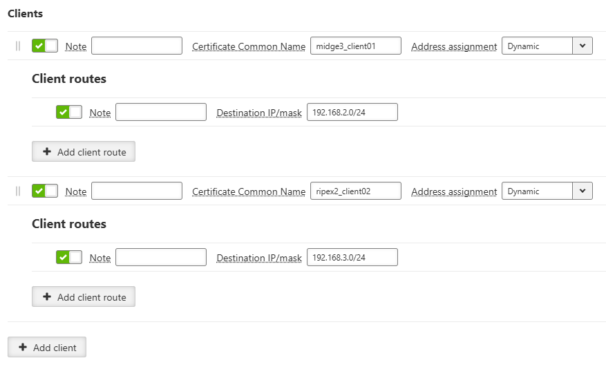
Clients:
- Enable client
Checkbox {On, Off}, default = “On”
Activate your client configuration. Deactivate the checkbox to turn off your client instance.
- Note
Text input
Add a custom description for your client.
- Certificate Common Name
Text input
Enter the Common Name attribute from your client certificate. The system uses this attribute to identify your client. OpenVPN replaces unsupported characters with an underscore.
- Address assignment
List box {Dynamic, Static}, default = “Dynamic”
Select your tunnel address allocation method for your client. Dynamic assignment requires an active dynamic client address setting on your server.
- Assigned address
IP address, default = “0.0.0.0”
Assign a specific IP address to your client. Apply this setting when your server operates in Router mode. Prevent IP address conflicts with other clients and your dynamic address pool.
Client routes:
- Enable route
Checkbox {On, Off}, default = “On”
Activate your client routing rule. Deactivate the checkbox to turn off your route.
- Note
Text input
Add a custom description for your client route.
- Destination IP/mask
IP address and mask, default = “0.0.0.0/0”
Define the destination network range for your packets. Prevent address conflicts with other active client routes. Your server uses this rule to direct traffic to your client and its subnets. Your server exports this route to other connected clients to enable direct client-to-client communication.
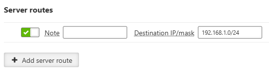
- Enable route
Checkbox {On, Off}, default = “On”
Activate your server routing rule. Deactivate the checkbox to turn off your route.
- Note
Text input
Add a custom description for your server route.
- Destination IP/mask
IP address and mask, default = “0.0.0.0/0”
Define the destination network range for your packets. Your server exports this rule to connected clients. This rule directs traffic from your client to your server and its subnets. Prevent address conflicts with other active routes on the same server.
- Enable server
Checkbox {On, Off}, default = “On”
Activate your server connection profile. Deactivate the checkbox to turn off your profile.
- Note
Text input
Add a custom description for your server profile.
- Server address
IP address or hostname, default = “0.0.0.0”
Specify your OpenVPN server IP address or hostname. You must enable DNS forwarding on your device to use a hostname.
- Connection protocol
List box {UDP, TCP}, default = “UDP”
Select your communication protocol with the server.
- Server port
Number [1, 65535], default = “1194”
Specify the destination port where your server listens.
- Accept packets from any address
List box {On, Off}, default = “Off”
Permit server packets arriving from varying source addresses. Use this setting when your server has a dynamic address or changes routing dynamically. Enable enhanced TLS protection alongside this setting.
- Connection retry period (initial) [s]
Number [1, 60], default = “1”
Set your initial connection retry interval in seconds. The interval doubles every five failed attempts until it reaches the maximum retry period.
- Connection retry period (maximal) [s]
Number [1, 600], default = “300”
Set your maximum connection retry interval in seconds.
- Connection timeout [s]
Number [1, 3600], default = “120”
Set your connection timeout limit in seconds. The system measures this limit from the start of the connection attempt with this profile.
- Connection fragmentation
List box {On, Off}, default = “Off”
Turn on internal data fragmentation between your participants.
- Fragment size [B]
Number [70, 1500], default = “1300”
Set your maximum UDP packet size for internal fragmentation.
- Restrict tunnel TCP MSS
List box {On, Off}, default = “On”
Turn on Maximum Segment Size rewriting in your TCP packets carried over the tunnel.
- Enhanced TLS protection
List box {Off, TLS Auth, TLS Crypt}, default = “Off”
Turn on additional protection for your OpenVPN control packets.
- TLS protection shared key ID
Keyring identifier
Select your shared key for additional control packet protection. The key must exist in your keyring with the OpenVPN TLS protection key (PRI) type. Match this key across all participants.
- TLS protection shared key direction
List box {0, 1}, default = “1”
Specify your key direction component for TLS Auth authentication on the client. Set this to the opposite value on your server.
| Warning | |
|---|---|
Attention is required to prevent routing loops, where traffic from the link between OpenVPN endpoints is directed back into the OpenVPN tunnel. Unlike IPsec, there is no protective mechanism against packet wrapping. |
User authentication is required to access M!DGE3 unit management. There are two types of user authentication which differ in the user account location:
Local authentication – user accounts are stored directly in the M!DGE3 unit
Remote authentication – user accounts are stored on a remote authentication server (RADIUS is implemented)
There are four different levels of user access privileges – they are bound with four different user access roles:
- Guest (role_guest)
Read only access for configuration parameters (except secured part of configuration). Diagnostics tools are available.
- Technician (role_tech)
All privileges of Guest role plus: write access for non-secured part of configuration; unit firmware up/down-grade.
- Security technician (role_sectech)
All privileges of Technician role plus: write access for secured part of configuration (except unit authentication related parts).
- Administrator (role_admin)
No access level restrictions. All privileges of Security technician role plus: user accounts management; remote authentication configuration.
Limitations:
Tab. 7.2: Overview of roles and rights in each section
| Section | Features | Roles / Rights | ||||
| Guest | Tech | Sec tech | Admin | |||
| SETTINGS | Interfaces | Ethernet, COM, Terminal servers, Cellular | Read-only | Write | Write | Write |
| Routing | Static | Read-only | Write | Write | Write | |
| Babel, OSPF, BGP, Link management | Non-visible | Non-visible | Write | Write | ||
| Firewall | L2, L3, NAT | Read-only | Write | Write | Write | |
| VPN | IPsec | Non-visible | Non-visible | Write | Write | |
| OpenVPN | Non-visible | Non-visible | Write | Write | ||
| GRE | Read-only | Write | Write | Write | ||
| Quality of service | Read-only | Write | Write | Write | ||
| Security | Policy | Non-visible | Non-visible | Non-visible | Write | |
| Local authentication | Non-visible | Non-visible | Non-visible | Write | ||
| Credentials | Non-visible | Non-visible | Non-visible | Write | ||
| Management access | Non-visible | Non-visible | Non-visible | Write | ||
| RADIUS | Non-visible | Non-visible | Non-visible | Write | ||
| Tamper reset | Non-visible | Non-visible | Non-visible | Write | ||
| Device | Unit | Read-only | Write | Write | Write | |
| Configuration | Read-only | Write | Write | Write | ||
| Events | Read-only | Write | Write | Write | ||
| Software keys | Read-only | Write | Write | Write | ||
| Firmware | Non-visible | Write | Write | Write | ||
| Services | Firmware distribution | Non-visible | Write | Write | Write | |
| SNMP | Non-visible | Non-visible | Write | Write | ||
| SMS | Non-visible | Non-visible | Write | Write | ||
| Hot standby | Read-only | Write | Write | Write | ||
| DIAGNOSTICS | Monitoring | Non-visible | Write | Write | Write | |
| Tools | Read-only | Write | Write | Write | ||
At least one Administrator type of account must be defined in the unit.
Maximal number of concurrently active sessions is 64. One user can have multiple sessions opened in the same time. If this limit is reached and a new session is to be opened, the oldest active session is deactivated and a new one is opened.
Maximal number of Local user accounts (all roles together) is 100.
Note The Remote access uses local identity and role of the user – there is no additional login to the remote unit (the login into local unit serves as login to the whole network).
- Passphrase – Minimal length
Number {5 – 64}, default = 5
The minimum length of the passphrase.
- Passphrase – Minimal number of lower case characters
Number {0 – 5}, default = 0
The minimum number of lowercase letters (English letters) which are required in the passphrase.
- Passphrase – Minimal number of uppercase characters
Number {0 – 5}, default = 0
The minimum number of uppercase letters (English letters) which are required in the passphrase.
- Passphrase – Minimal number of digits
Number {0 – 5}, default = 0
The minimum number of number characters (0 to 9) which are required in the passphrase.
- Passphrase – Minimal number of special characters
Number {0 – 5}, default = 0
The minimum number of special characters (not English upper or lower cases or numbers) which are required in the passphrase. Non-English letters (like Greek, Russian, Arabic) are counted as special characters.
This setting applies to the download of Credentials, Users, Configuration backups, and Diagnostics packages. The Require encrypted backup and restore parameter enforces the use of encrypted files for all users. The following parameters allow you to define passphrase complexity rules for encryption.
The following settings are available only for user with the Administrator role.
Following user account parameters can be changed: password, user role. Any account (expect the last one of Administrator role) can be deleted.
Export all users button provides backup of all Local user accounts into a file.
Import all user button provides restoration of all Local user accounts from a backup file. Active session is logged out automatically after this command.
+ Add user account button invokes new user account creation dialog:
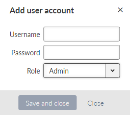
- Username
String {1–128 char}, default = <empty>
New Username. Every username in the unit must be unique.
- Password
String {5–128 char}, default = <empty>
Password is stored in a secure way.
- Role
List box {Admin; Security Technician; Technician; Guest}, default = “Admin”
Note It is highly recommended to create a new administrator type of account and delete the default “Admin” account.
Export all users
The exported user accounts are stored in a text file (.json file type) or in an encrypted .zip file. The rules for encryption (forced requirement and password complexity) shall be set in SETTINGS > Security > Policy see section 7.5.1 Policy.
Overwrite all users
All existing current users will be deleted and replaced by users stored in imported file. You will be logged off after the import and you have to log in using the imported user account.”
Advanced feature
When the user account is not active for some time, the user will be automatically logged-out. The inactivity timeout of the account is set for 1 day by default. It is possible to change in the range of 5 minutes up-to 2 days (menu ADVANCED > Generic > UserAccess > Web inactivity timeout).
Allows to set password complexity rules.
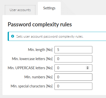
- Min. length [No]
Number {8 – 64}, default = 8
The minimum length of the password for all users.
- Min. lowercase letters [No]
Number {0 – 5}, default = 1
The minimum number of lowercase letters (English letters) which are required in the user password.
- Min. UPPERCASE letters [No]
Number {0 – 5}, default = 1
The minimum number of uppercase letters (English letters) which are required in the user password.
- Min. numbers [No]
Number {0 – 5}, default = 1
The minimum number of number characters (0 to 9) which are required in the user password.
- Min. special characters [No]
Number {0 – 5}, default = 1
The minimum number of special characters (not English upper or lower cases or numbers) which are required in the user password. Non-English letters (like Greek, Russian, Arabic) are counted as special characters.
Note The settings are applicable for new passwords only, already existing passwords will not be affected.
M!DGE3 units feature a unified storage solution for keys, certificates and other credentials. This storage is secured and only accessible to users with Sectech permission and higher.
Credentials are separate from configuration to improve security and it also is protected using checksum to prevent unauthorised modification. Because of this all Repository/Key changes are executed immediately and do not go through the “Changes” workflow like the regular configuration.
Note: In this manual and in the user interface we are calling all Credential storage entries “Keys”. While this is a simplification, we believe it is understandable. Further on “Keys” are all keys, public and private certificates, DH parameters, CA chains etc.
Warning: Downgrading the Unit will always reset all Credentials to defaults.
Credentials are stored in Repositories. Repository is a reserved space, which contains 0-1 Key and is addressable via its ID in the rest of the unit configuration. This construct, while it may seem complicated at first, brings major benefits. Mainly the user can simply update expired certificates in a repository without any need to change configuration using that Repository.
There are two types of Keys: Read-only, easily identifiable by a lock icon and “_RO_” prefix. These Keys are built into firmware, or generated automatically on device. The rest are user-defined keys.
Admin website allows users to perform various operations with the keys and repositories.
Using buttons on the bottom of the page we also allow users to download complete credential backup.
There are two ways to restore credentials: Replace, which replaces all Keys with ones from the file, and Update, which merges current and new Keys.
Credentials show all Repositories and Keys currently on the device. Users can filter them by type and show only valid or all Keys. The card border and bottom label indicate whether the Repository is empty, or whether the Key is valid or invalid.
Each card represents a Repository. Card title is Repository ID. All user-defined repositories can be edited using the “Edit” button and deleted using the red “Delete” button.
- ID
Unique identifier used to reference Repository in configuration.
Validated according to regular expression: [a-zA-Z0-9\_]\\{1,128\\}. IDs starting with underscore “_” are reserved for Read Only keys.
- Type
Defines the type of Key the Repository can contain.
- Note
Optional comment.
There are several operations, that can be performed on a repository:
- Info
Displays Key info including checksums.
- Generate
Generates a new Key using local Certification authority (see below).
- Update
Updates the Key with a new one. Both file and text, encrypted and unencrypted Keys are supported.
- Download
Allows download of the Key. Both encrypted and unencrypted downloads are supported. The rules for encryption (forced requirement and password complexity) shall be set in SETTINGS > Security > Policy see section 7.5.1 Policy.
- Generate CSR (Certificate Signing Request)
Generates and downloads CSR from eligible Keys.
- Sign CSR (Certificate Signing Request)
Signs CSR. Both file and text certificates are supported. Signed certificate is automatically downloaded. It is possible to add “extended key usage” Certificate modifier for OpenVPN client/server.
Operation “Add repository” creates an empty Repository.
Shortcut operations “Generate credential” and “Add credential” allow users to create a Repository and generate/upload a key into it. These buttons cannot be used to modify existing repositories.
- _RO_Ssh_Host_Key
Type: SSH Key (PRI)
The SSH host key used to authenticate the server on the client. If missing, it is generated when the station boots.
- _RO_Rmt_Access_Host_Key
Type: RMTACCESS Key (PRI)
Host key for the Remote access server (QSSH). It is used to authenticate the server.
If missing, it is generated when the station starts.
- _RO_Rmt_Access_Client_Key
Type: RMTACCESS Key (PRI)
Key for Remote access (QSSH) client login to the server. Must be present on both sides.
Obtained from FW. If it differs from the version in FW, it is updated.
- _RO_Web_Private_Key
Type: Certificate (PRI)
Web server private key (default).
Obtained from FW. If it is different from the version in FW, it is updated.
- _RO_Web_Cert
Type: Certificate Key (PUB)
Web server certificate (default).
Obtained from FW. If it is different from the version in FW, it is updated.
- _RO_Web_CA_Chain
Type: CA Chain (PUB)
The certificate string of the authority that signed the Web server certificate. If self-signed, it will be empty.
Retrieved from FW. If it differs from the version in FW, it is updated.
- _RO_Web_DH_Param
Type: DH Parameters (PUB)
Parameters for the Diffie-Hellman key exchange in the Web server.
Retrieved from FW. If it differs from the version in FW, it is updated.
- _RO_File_Distribution_Key
Type: UFTP Key (PRI)
Key for authenticating stations in the “File distribution” (UFTP) service.
Obtained from FW. If it differs from the version in FW, it is updated.
This tab displays additional settings needed for Local CA authority and Passphrase complexity rules for Key downloads.
Local authority
- Private key ID
Private key used for local certification authority.
- Certificate ID
Public certificate used for local certification authority.
- Signature algorithm
Algorithm used for certificate signing. It depends on the Certification Authority key algorithm and may not be used in case CA uses a specific algorithm.
- Expiration period (days)
Expiration period in days. Default 7300.
Contains organisation identification used for certificate generation.
Country
Country code (pre filled automatically, possible to manually set by using “Other” in “Country”)
Organisation
Department
Location
State
Common name
E-mail
To create local CA you need to follow these steps:
Generate a new private certificate “Certificate key (PRI)”
Generate a new “CA Chain (PUB)” using certificate created in previous step as “Certificate key”
Activate Local CA by going to Settings tab and activating Local CA, selecting newly created “Private key ID” (= new private certificate “Certificate key (PRI)”) and “Certificate ID” (= new “CA Chain (PUB)”)
| Note | |
|---|---|
Web server private key must use “RSA” or “EC (ECDSA)” algorithms. Other algorithms are not supported by web browsers. |
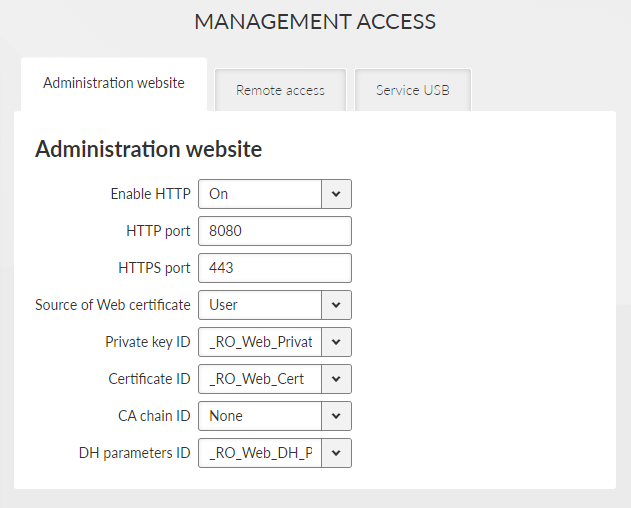
Enable HTTP | List box {On; Off}, default = “On” Enables HTTP access to the station. When enabled, HTTP immediately redirects to HTTPS. |
HTTP port | Number {1 – 65535}, default = 80 The TCP port number on which HTTP access is available. |
HTTPS port | Number {1 – 65535}, default = 443 The TCP port number on which HTTPS access is available. |
Source of Web certificate
List box {Default; User}, default = “Default”
Choses source of Web server certificate. “Default” uses key, certificate and DH parameter distributed in FW (see SETTINGS > Security > Credentials), default values are as follows:
Private key: _RO_Web_Private_Key
Certificate : _RO_Web_Cert
CA chain: _RO_Web_CA_Chain”: CA chain, of the CA which signed the certificate. For self-signed certificate shall remain empty – None).
DH parameters: _RO_Web_DH_Param
Web inactivity timeout [min] | Number {5 – 2880}, default = 1440 When the inactivity timeout is reached, the HTTPS session terminates. Available in ADVANCED > Security > Management access menu. |
“User” allows to use user key and certificate included in the Credentials storage. Add your certificate and other files using menu SETTINGS > Security > Credentials. In the individual list boxes will be shown available certificate of keys for each category and you can choose those previously added.
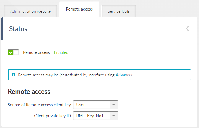
- Enable/Disable
If enabled, allows the unit to be accessed via the Remote access feature.
Note Remote access is enabled or disabled globally in this menu. Individual settings for each interface are available in the ADVANCED menu. By default, Cellular and Ethernet interfaces are enabled, while all other interfaces are disabled. The current settings are displayed in the Status area.
- Source of Remote access client key
List box {Default; User}, default = “Default”
- Client private key ID
When the User in list box above is chosen, then you cab select a key previously downloaded to the Credentials storage (SETTINGS > Security > Credentials) or or generated in the same menu. The Remote access key has to be the same for the whole network (or the part of it for which you will use the Remote access). The remote access to the unit with different Remote access key is not possible.
| Note | |
|---|---|
The use of a dedicated Client private key is highly recommended. |
The USB service interface primary purpose is to provide unit service and management access. Ethernet or Wi-Fi connection can be established using an external ETH/USB or Wi-Fi adapter.
Only adapters supplied with the product can be used for this purpose.
See list of available adapters.
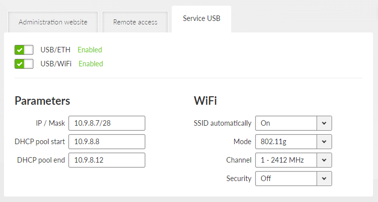
The DHCP server is running on this service interface to enable easier connection of the management device (PC, tablet or smart phone).
- Enable / Disable
Each of the ETH or Wi-Fi service can be enabled or disabled separately. When the Wi-Fi is enabled, the unit acts as a Wi-Fi Access Point (AP).
- IP address / Mask
IP address, default = 0.0.0.0/0
IP address of the DHCP server. This is the IP address to be used when accessing the unit management via this serial interface.
- DHCP pool start
Default = IP address of the DHCP server + 1
DHCP Server assigns addresses to connected clients starting from this address.
- DHCP pool end
DHCP server assigns IP addresses to connected clients in the range defined by DHCP pool start and DHCP pool end (inclusive).
- Wi-Fi
Wi-Fi AP parameters can be customized.
- SSID automatically
List box {On; Off}, default = “On”
When automatic definition of SSID is enabled, the SSID contains unit Serial number.
- SSID
Wi-Fi AP SSID. When entered manually, it must follow SSID naming conventions.
- Mode
List box {802.11g; 802.11g }, default = “802.11g ”
Wi-Fi AP mode.
- Channel
Selected Wi-Fi channel.
- Security
List box {Off; WPA2-PSK}, default = “Off”
It is a good practice to use WPA2-PSK secured connection together with a strong password. It is highly recommended in case of permanent Wi-Fi adapter installation.
User accounts can be managed centrally with an authentication server. RADIUS client-server protocol is used for remote authentication. RADIUS accounts can be mapped to one of the four user roles. This is either managed by the server itself or by local M!DGE3 settings.
Local accounts are checked first and if the account does not exist, RADIUS accounts will be used. If the RADIUS server is not accessible, users may use the local username/password to “fall back” to local authentication.
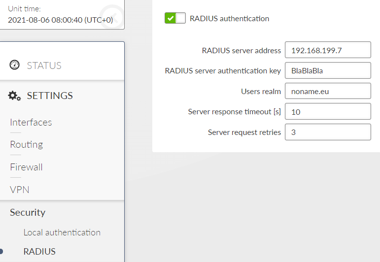
Menu SETTINGS > Security > RADIUS allows to set all the main parameters.
- RADIUS server address
IP Address of RADIUS server used for authentication.
- RADIUS server authentication key
Text {0 – 32 characters}
Password to authenticate against the RADIUS server.
- User realm
Text {must contain at least one dot “.”}
Realm allows to shorten the login name – e.g. when the full login name is “tech@noname.eu” and the realm is “noname.eu” the Username filled in the login page is only “tech”.
- Server response timeout [s]
Number {1 – 30}, default = 10
Time measured while waiting to the server’s response before sending a request retry.
- Server request retries
Number {1 – 7}, default = 3
Number of request retries in case of M!DGE3 did not receive a valid reply.
Additional expert parameters shall be set in the ADVANCED menu.

The level of access is realised by Management-Privilege-Level (RFC 5607, index 136, type integer). The level for each account shall be set during the server configuration. The user access level will be granted according to the integer ranges for individual role levels. When the server does not allow setting of Management-Privilege-Level the static account level option (for all users) has to be used.
Tamper is a detection service, which is triggered, when the M!DGE3 chassis is physically opened. There are 2 contacts (securing top and bottom casing) and the event is triggered even if the unit is without power. When the chassis is opened an alarm is triggered and shown in Status report. Triggered Tamper stops the RTC (real time clock) which means, that every unit reboot resets the unit timer back to the time, when the Tamper was triggered. See the STATUS menu:
| Note | |
|---|---|
M!DGE3e has not the Tamper detection functionality. |
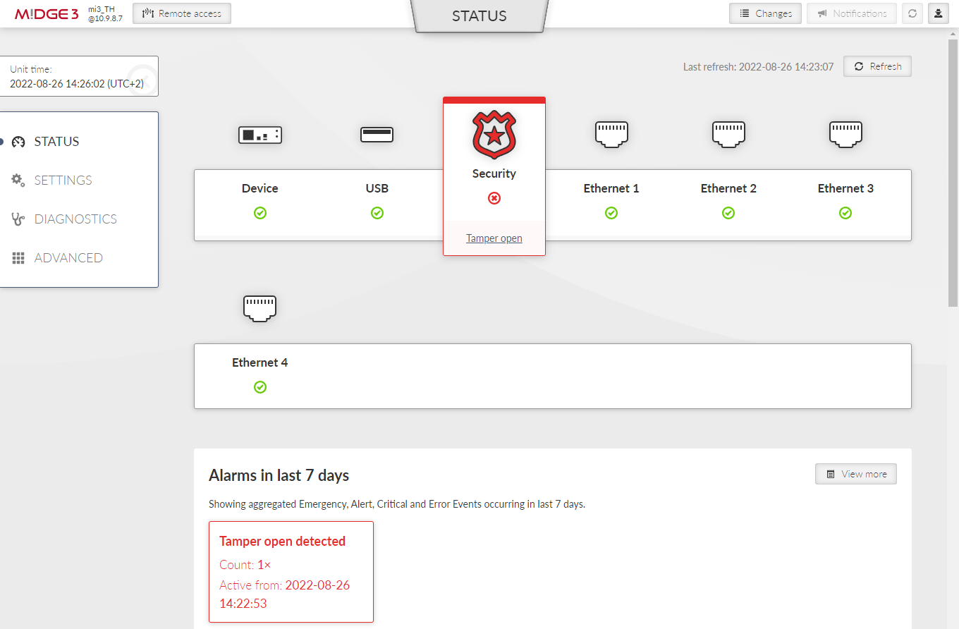
To solve Tamper alarm, re-assemble the unit, via admin user account see SETTINGS > Security > Tamper reset in the menu and click the “Reset tamper” button.
| Note | |
|---|---|
The unit must be re-assembled before clicking the “Reset tamper” button, otherwise it returns an error. 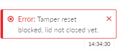 |
Whole process can take a while and ends by rebooting the unit.

If an automatic time synchronization is not set, the time in the RTC needs to be set manually.
The general settings affecting the whole unit.
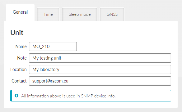
- Unit name
This name is used as a real name of the Linux router, so the allowed characters are strictly limited to:
Text; default = _a..zA..Z0..9
- Unit note
Text; default = _a..zA..Z0..9
Longer unit name without special characters restrictions.
- Unit location, Unit contact
Text; default = _a..zA..Z0..9
Additional SNMP information. All the fields above are typically used in the NMS systems to identify the specific unit.
Unit Event time stamps, unit Statistics records and unit internal logs are using Unit time. It is good practice to keep the Unit time synchronized to ease unit and network diagnostics.
Unit time can be setup manually or it can be synchronized with an NTP server. NTP server synchronization is recommended.
The unit itself serves as an NTP server providing the time synchronization to another IP clients. If no NTP server is defined or no one is available, the unit runs in an “orphan” mode. The unit internal NTP server Stratum is set to 8 in this case. If the unit is synchronized with an NTP server, the unit NTP server Stratum is set a 1 higher comparing to Stratum of the NTP server providing the time synchronization to the unit.
If the unit is synchronized to a time source and the unit (synchronized) time differs from the unit RTC time (by more than 8 seconds), the RTC time is updated.
| Note | |
|---|---|
Each unit can serve as NTP server for further IP equipment, this functionality is always on. |
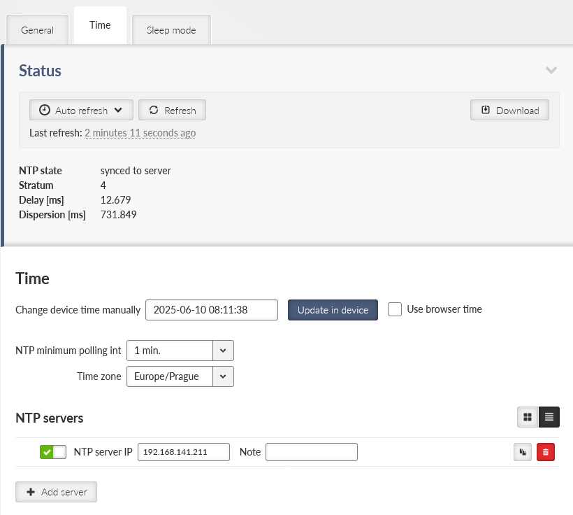
- Status
The Status field provides information about NTP synchronization status.
Refresh button is used to update the Status information.
- Change device time manually
This field is used to setup unit time manually.
- Update in device
Sets the given time to the unit.
- Use browser time checkbox
Continuously updates the Change device time manually field to minimize the delay between the time input and the moment of time setup.
- NTP client synchronization source
Synchronization source of the NTP client. The only option “NTP server” is implemented at this firmware version.
- GNSS synchronization
List box {On; Off }, default = “Off”
Enables / disables synchronization with the GNSS (GPS) (when optional GNSS module is used). Not only GNSS data, but also precise time pulses generated by the GNSS module are used for time synchronization. GNSS (GPS) synchronisation has priority over other NTP sources. This parameter occurs only if GNSS (GPS) is enabled in Section 7.6.1.4, “GNSS (GPS)”.
- NTP server minimum polling time
Minimal period of the NTP server queries. NTP client is allowed to prolong this time in case of poor quality of the server or connection to the server.
- Time zone
Time zone to represent unit internal time. All the unit timestamps are displayed using this time zone. Changing the time zone does not affect unit internal records – they are always recorded using UTC time zone.
NTP status information is based on standard ntpq daemon status output (ntpq -c lpeers, ntpq -c rv) – see https://docs.ntpsec.org/latest/ntpq.html (system, peer and clock variables) for details.
Multiple NTP servers can be configured to get more precise time synchronization or to have a backup solution in case of an individual NTP server unavailability. Maximum number of records in the list is 32. The unit runs in an “orphan” mode if the NTP client synchronization source is set to “NTP server” and there is no NTP server defined in this list.
Enable / Disable | Enables / Disables a NTP server. |
NTP server IP | Defines the IP address of the NTP server. |
Note | Informational comment. |
M!DGE3 offers a mode which periodically switches between the full traffic mode and low power consumption mode. This mode is suitable e.g. for power-consumption sensitive applications. When in Sleep mode, M!DGE3 has extremely low power consumption (10 mW). The time needed for a complete wake-up from the Sleep mode (booting time) is approx. 45 seconds or more – depending on the configuration. Sleeping unit indicates its state by green flashing SYS LED.
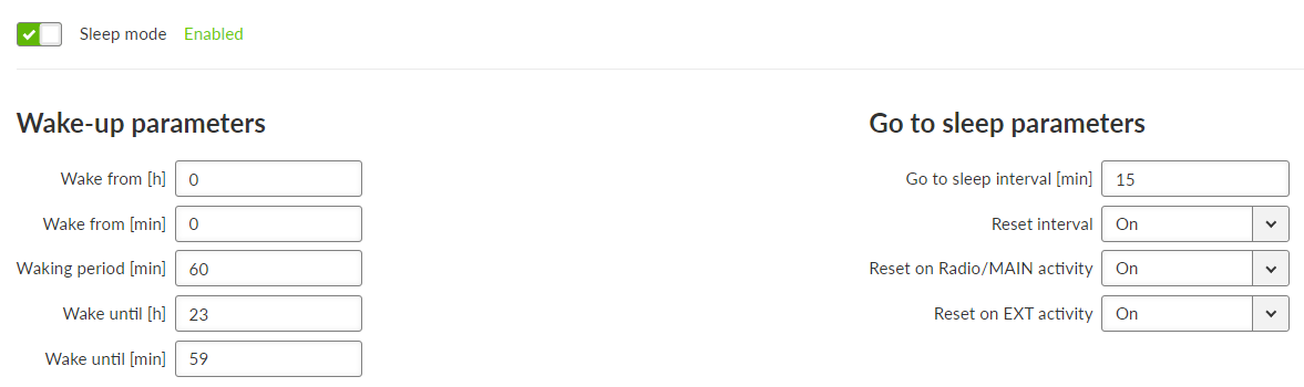
- Sleep mode
Enable / disable, default = disable
Enables / disables Sleep mode. When enabled, the unit will periodically go into Sleep mode depending on conditions defined by the following configuration.
Waking up the M!DGE3 from Sleep mode is possible via setting the time of its awakening. It is also possible to set an interval during which the unit will be woken up regularly. Sleep mode time boundaries are counted in a set Time zone (SETTINGS > Device > Unit > Time).
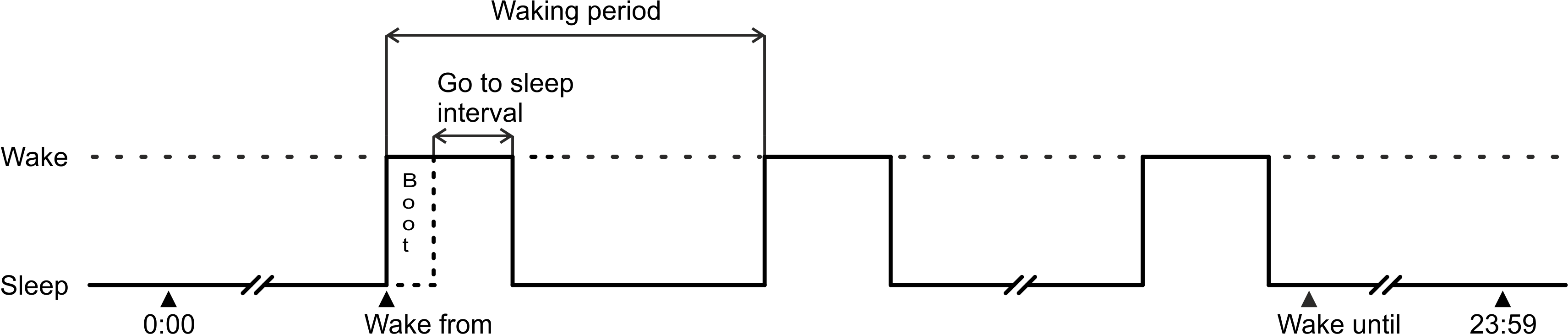
- Wake from [h]
Number {0 – 23}, default = 0
Defines the first wake-up time in a day – hour.
- Wake from [min]
Number {0 – 59}, default = 0
Defines the first wake-up time in a day – minute.
- Waking period [min]
Number {0 – 1439}, default = 60
Defines the length of time period (min) between individual wake-ups.
- Wake until [h]
Number {0 – 24}, default = 23
Defines the time in a day after which the unit will not be awaken – hour.
- Wake until [min]
Number {0 – 59}, default = 59
Defines the time in a day after which the unit will not be awaken – minute.
| Note | |
|---|---|
Set time from parameters Wake from [h] and Wake from [min] must be smaller or equal to set time from parameters Wake until [h] and Wake until [min]. |
M!DGE3 will go into the Sleep mode after the set time passes. It is possible to delay the Sleep mode to assure that all data transfer is complete. Connecting USB-ETH or USB-Wi-Fi adapters to the service port will also delay the Sleep mode. Falling into the Sleep mode will generate an event to the Event log.
| Note | |
|---|---|
If the M!DGE3 is in the Sleep mode and a power outage occurs (for approx. 10s), the Sleep mode will be interrupted and the unit will wake up (boot). |
- Go to sleep interval [min]
Number {5 – 1439}, default = 15
Defines the length of time (min) after which the unit will go into Sleep mode. The countdown starts, when the unit is completely awake.
- Reset interval
List box {On; Off }, default = “Off”
Allows to set conditions causing the unit to delay transition into Sleep mode by resetting the count down timer back to the initial value Go to sleep interval [min].
- Reset on Radio/MAIN activity
List box {On; Off }, default = “On”
If the unit shows activity on the Cellular-MAIN interface, the count down timer is reset back to the initial value Go to sleep interval [min].
Note ICMP ping on Cellular-MAIN interface will not trigger the Reset on Radio/MAIN activity.
- Reset on EXT activity
List box {On; Off }, default = “On”
If the unit shows activity on the Cellular-EXT interface, the count down timer is reset back to the initial value Go to sleep interval [min].
Note ICMP ping on Cellular-EXT interface will not trigger the Reset on Radio/EXT activity.
- Example 1:
With following settings M!DGE3 will be periodically woken up every hour for 10 minutes (all day long):
Wake from [h] = 0
Wake from [min] = 0
Waking period [min] = 60
Wake until [h] = 23
Wake until [min] = 59
Go to sleep interval [min] = 10
Reset interval = Off
- Example 2:
With following settings M!DGE3 will be periodically woken up from 7:00 to 16:00 every 30 minutes for 10 minutes:
Wake from [h] = 7
Wake from [min] = 0
Waking period [min] = 30
Wake until [h] = 16
Wake until [min] = 00
Go to sleep interval [min] = 10
Reset interval = On
Reset on Radio/MAIN activity = On – this parameter will ensure that M!DGE3 stays awake in case of any Cellular activity at the scheduled sleep time.
Sleep Input (SI) is a trigger signal that can be used to wake up a station from sleep.
SI is trigged/activated if it is pulled below 1.1 VDC. See more details in Pin assignment
If the M!DGE3 is in the Sleep mode and SI is triggered, the unit will wake up for the set awake period and go back to sleep. The Sleep Input signal is not monitored while M!DGE3 is awake so any additional SI trigger does not increase the awake period.
- Example:
The unit is set to be waking up every hour for 10 minutes.
If a unit were to receive a SI command at 10:15 it will wake up and be awake until 10:25.
Unless another SI command is received after 10:25 the unit will stay asleep until 11:00
GNSS (Global navigation satellite system) allows the optional extension module to provide information about the units location and enable a precise time synchronization.
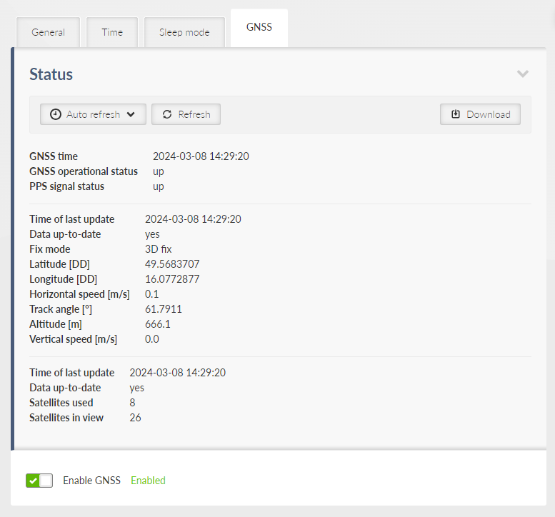
- Enable; Disable, default = “Disable”
Enables / Disables the GNSS (GPS).
To set up GNSS (GPS) see Section 7.7.6, “GNSS server”.
Tab. 7.3: LED behavior of GNSS (GPS)
| LED | Colour | Status | Function |
|---|---|---|---|
| EXT | Green | Flashing regularly – period 1000 ms | GNSS (GPS) is active, awaiting for data about location and PPS signal. |
| EXT | Green | Permanently lit | GNSS (GPS) is active, data about location and PSS signal is available. |
Configuration in M!DGE3 operates on following system:
Current configuration – displayed configuration, which is seen in the web client.
Running configuration – actual configuration, running in the M!DGE3 unit.
Stored configuration – configuration stored in the M!DGE3 unit. This configuration is stored in the unit, even when its turned off.
Factory settings – default configuration.
Changes – all changes done to the Current configuration (in the web client). For more information see Section 6.2, “Changes to commit”.
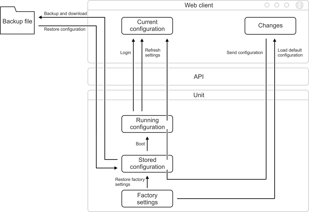
There are several tools to operate full unit configuration:
- Backup
It is a good practice to make a configuration backup into an external file every time the configuration is changed, to be able to restore the configuration into another unit in case of unit maintenance.
Backup and download button triggers the web browser Download action. The specific behavior depends on your web browser personal settings – whether the configuration backup file is downloaded to a predefined download folder or the file Download dialog to select destination folder is shown. The configuration is stored in a text file (.json file type) or in an encrypted .zip file. The rules for encryption (forced requirement and password complexity) shall be set in SETTINGS > Security > Policy see section 7.5.1 Policy.
The backup configuration has following limitations:
The set of configuration data is limited by a user access privileges of the user who performed the backup. The full configuration backup can only be issued by a user with the Administrator (role_admin) access privileges. The same user access limit applies when the configuration is restored (i.e. the full configuration Restore can only be issued by a user with the Administrator (role_admin) access privileges).
Configuration version is stored in the parameter called “CNF version” which can be checked in the menu: DIAGNOSTICS > Information > Device > Advanced information.
- Restore
The configuration can be restored from a backup file (containing the same configuration version as the configuration version currently running in the unit – see above).
- Choose File Button
Triggers the file selection dialog. Once the configuration backup file is selected, it is uploaded to the unit. The upload action can take some time – depends on the speed of your service connection to the unit.
- Factory settings
Load default configuration button loads default values of all configuration parameters into the web interface. All parameters whose current value differs from the default are marked as changed. They are listed in the Changes to commit dialog. They do not affect the running unit until eventually sent to the unit by the Send configuration button.
Note This action can be used (for example) to check which set of parameters differs from the default value.
- Restore configuration button
Enabled after the backup configuration is uploaded. Press the button to restore the unit configuration. The configuration restore result is reported as an error message (in case of failure) or Notification center success message:
- Restore factory settings
Restores all configuration parameters to default setup (including monitoring settings). Logout from station will apply.
Deletes user database.
- Total purge
Restores all configuration parameters to default setup (including monitoring settings). Logout from station will apply.
Deletes user database.
Deletes all diagnostic logs and statistics.
| Note | |
|---|---|
Basic data such as Code, Region, SW keys will always remain in the unit. |
| Warning | |
|---|---|
This action can take up to two minutes – do not power off the unit until finished. |
Configuration validation
FW from version 2.2.0.0 introduces an improved configuration validation process. In older FW versions, some configuration item validations (e.g., allowed value range, string length) were validated only in the web application (front-end). When modifying the configuration in other ways (API calls, direct editing of the backup configuration file), it was possible to enter a value into a configuration item that caused the resulting unit configuration to be invalid. Recently, full configuration validation is performed directly in the unit (back-end). No method of configuration change (web interface, API, text backup modifications) can cause the unit to use an invalid configuration.
Notice for upgrading FW from older versions to version 2.2.0.0 and
higher:
Units with FW older than 2.2.0.0 may have worked with a configuration
that is not fully valid. Upon upgrading the unit to FW 2.2.0.0, or higher, a configuration
validity check will be performed during startup the unit. If the configuration fails this
check, the user will be informed by the generation of the system event
“EVENT_CNF_BOOT_ERROR”. The notification center will provide detailed alarm messages
referencing individual invalid configuration items. However, the unit will continue to
operate with this configuration as it did before the FW upgrade. The functions of the unit
are not affected by this situation.
Consequences of running the unit with an invalid configuration:
The system
event “EVENT_CNF_BOOT_ERROR” is active. The event has a default severity of Alarm, which
causes the SYS status LED to light up red.
Until all items that failed the validation process are corrected, no configuration changes can be saved. The updated configuration can only be activated once the entire configuration successfully passes validation.
Tab. 7.4: Configuration versions
| CNF version | FW version |
|---|---|
| 31 | 2.3.6.0 |
| 30 | 2.3.4.0 |
| 29 | 2.2.9.0 |
| 28 | 2.2.6.0 |
| 27 | 2.2.4.0 |
| 26 | 2.2.2.0 |
| 25 | 2.2.1.0 |
| 24 | 2.2.0.0 |
| 23 | 2.1.7.0 |
| 22 | 2.1.6.0 |
| 21 | 2.1.2.0 |
| 20 | 2.1.1.0 |
| 19 | 2.1.0.0 |
| 18 | 2.0.18.0 |
| 17 | 2.0.16.0 |
| 16 | 2.0.14.0 |
| 15 | 2.0.13.0 |
The Status section displays the Configuration checksum. This checksum is unique to each unit and its current settings. Any modification to the configuration will result in a different checksum value. The checksum can also be retrieved via an API call.
Settings of the severities of the individual events. Some events can generate SNMP notification and can change level of the HW alarm outputs (AO, DO1, DO2) see Section 2.2.2, “Power and Control”. Events can also generate SMS notifications, which are being sent to a defined phone number (see Section 7.7.5, “SMS”).
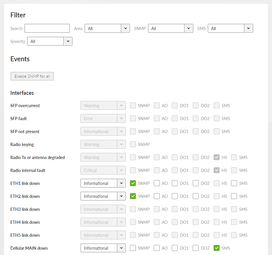
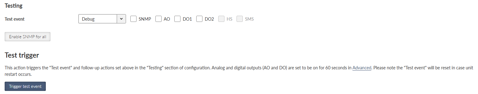
Pressing the “Trigger test event” button will activate the ‘Test event’ along with any subsequent actions defined in the ‘Testing’ configuration section . Specifically, the analog and digital outputs (AO and DO) will be active for 60 seconds (can be changed in Advanced menu).
| Note | |
|---|---|
Unit restart will reset the Test event. |
Certain M!DGE3 features needs to be activated by a SW key to be available. When the respective SW key is not present, the feature cannot be configured. If the feature is enabled in a configuration backup file and the file is loaded to a unit which is not equipped with the respective key, the configuration is refused (no changes are made in the unit).
Here is the list of available SW keys and their assignment to offered SW key packages.
SW key(s) can be obtained from your supplier. It is delivered as a text file containing the key(s). Every SW key is unique for the specific unit (specific serial number). Use Choose File dialog to select the file and Install key button to install the key(s) to unit.
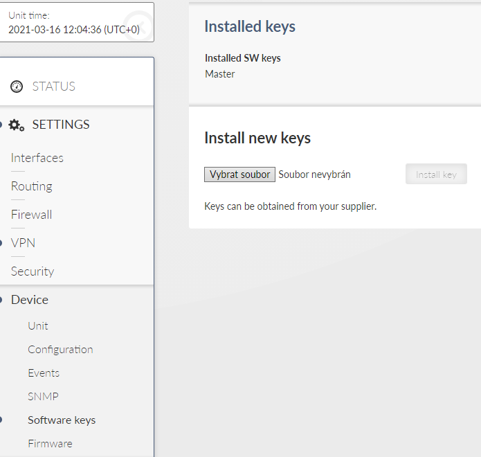
Tab. 7.5: List of atomic SW keys
| Atomic key | Shortcut | SW key | Without Key |
|---|---|---|---|
| BGP** | BGP | By defaults | NA |
| OSPF** | OSPF | NA | |
| Babel** | Babel | NA | |
| Link management** | LMgmt | NA | |
| PPPoE*,** | PPPoE | NA | |
| IPsec | IPsec | By defaults | NA |
| OpenVPN | OpenVPN | NA | |
| Multiple users | Users | Only one user | |
| RADIUS | Radius | NA | |
| Tamper detection** | Tamp | NA | |
| SFP** | SFP | SFP | NA |
*By defaults from 03/2024, if you’ve purchased M!DGE3 before this date and want to use this functionality, you will need to request the atomic key from the supplier.
**Not available for M!DGE3e
| Note | |
|---|---|
The newly added atomic keys are not included in the delivery of the previously ordered SW key (Link management for units dispatched before 07/2023, OpenVPN for units dispatched before 10/2023). Dispatch date is a part of Quality Inspection Report, which is available for each individual S/N via RACOM’s WebService. Installed atomic keys you can check using menu SETTINGS > Device > SW keys. Master key substitutes all atomic keys (even these newly and in future added) |
Unit firmware defines the unit functionality. There are several principles for managing the firmware in the running network:
Maintain the same version of firmware in the network (recommended). M!DGE3 units are able to cooperate with different versions of firmware running, but using the same firmware version in all units is the best way to keep the network maintenance simple.
Upgrading firmware to a newer version is not obligatory, unless there are bug/security fixes etc.
The cyber security issues may force the firmware to be upgraded e.g. when some serious security vulnerability was fixed.
Follow this recommended sequence to update your device from legacy versions:
- Step 1:
Update from 1.X.X.X to 2.0.10.0.
- Step 2:
Proceed to 2.1.0.0.
- Step 3:
Move to 2.2.4.0.
- Step 4:
Advance to 2.2.6.0 or 2.2.9.0.
- Step 5:
Install the latest version (2.3.4.0 or higher).
This multi-step process ensures stability when you transition from older firmware versions.
There are 3 stages of the firmware upgrade procedure:
Choosing new firmware and loading it into the web browser.
Uploading new firmware into the unit’s internal archive.
Activating the unit firmware.
Every operation can take up to several tens of seconds.
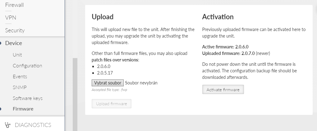
The Status section displays the Firmware checksum. This checksum is unique to each individual unit, differing even between units with the same firmware version. The checksum can also be retrieved via an API call.
| Note | |
|---|---|
Unit configuration backup is recommended after the firmware upgrade. See Section 7.6.2, “Configuration”for details. |
To upgrade the firmware:
Optional (recommended): Backup the current unit configuration (menu SETTINGS > Device > Configuration – Backup and download).
Download the required firmware from the Racom web: Products – M!DGE3 – Download – Firmware M!DGE3 – midge3-fw-x.x.x.0.fwp
Click the Choose File button (the button label may differ based on your web browser localization) to select the firmware file.
Click the Upload firmware button to transfer the firmware file into the unit. The upload can take a long time – depending on the connection speed between the management PC and the M!DGE3 unit. In case of slow connection and file transfer longer than 120 s, the web browser will shut down the connection and the action will not finish successfully. This action does not update the running unit firmware yet. There is no affection on the other communication running through this unit. Successful uploading of the new firmware into the archive is announced in the Notifications and the available firmware version is highlighted under the “Activation” heading as “Uploaded firmware:“.
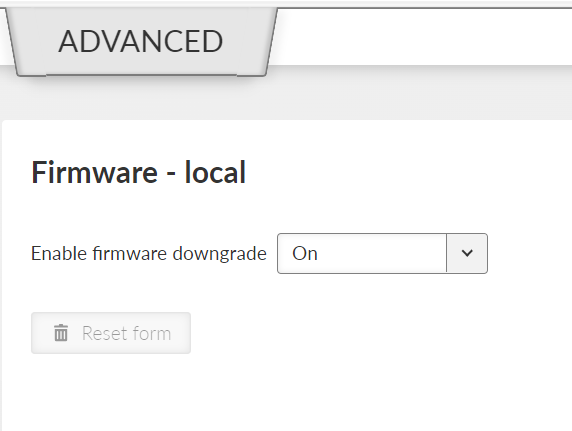
Note Admin level account has a possibility to dissable FW downgrade (menu ADVANCED > Firmware > Firmware – local by seting of the Enable firmware downgrade to Off), by default is this functionality allowed.
Click the Activate firmware button to upgrade (i.e. reinstall) the unit firmware. The upgrade process takes approx. one minute. The user data communication running through this unit is interrupted for a while. All the processes are restarted in a certain moment (e.g. VPN tunnels need to be re-established).
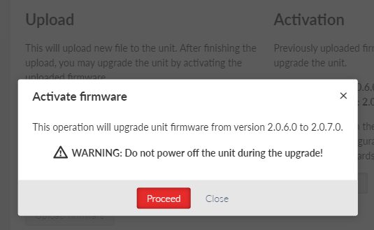
![[Warning]](/images/radost/images/icons/warning.png)
Warning Do not shut down the unit during the firmware update process. It may permanently damage the unit.
It is possible not only to upgrade the firmware version, but to even downgrade it, although this operation is not recommended. Be aware of eventual security issues of firmware downgrade as eventually outdated security code can be part of an old firmware. After FW downgrade, all unit parameters will be set to factory defaults.
In some cases, instead of uploading and activating full FW version, patch files can be used. Advantage of the patch files is that they are smaller comparing to the full version files. For successful activation a compatibility between the patch file and active firmware (or uploaded firmware) must be ensured. Patch files for M!DGE3 can be downloaded from ’s web site. FW versions stored in M!DGE3 are displayed in SETTINGS > Device > Firmware.
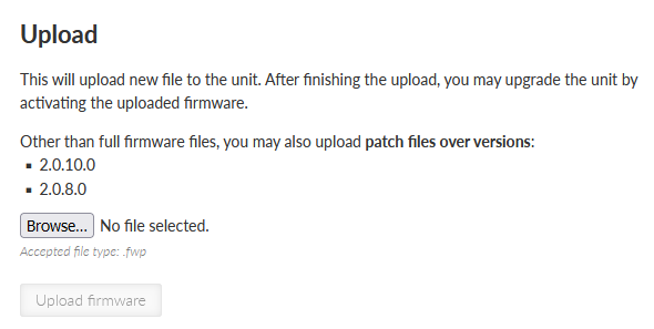
Example: There are 2 older FW versions (2.0.8.0 and 2.0.10.0) stored in M!DGE3 (picture above).
For successful activation of newer FW version (e.g. 2.0.13.0) using patch file either:
Download patch files version upgrading from 2.0.8.0 to 2.0.13.0 or
Download patch files version upgrading from 2.0.10.0 to 2.0.13.0 (recommended, because this patch file will be smaller).
The result will be the very same in both cases.
| Note | |
|---|---|
FW versions (both patch files and full versions) are stored in M!DGE3 archive . |
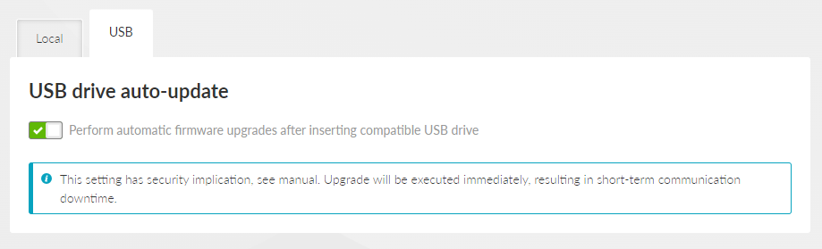
Switch Perform automatic firmware upgrades after inserting compatible USB drive allowing FW upgrade from a USB flash disk. Downgrading using a USB disk is not possible. The change of this setting is activated after a new boot process.
The FW of the unit itself will be upgraded (not the FW of an eventual embedded module).
When allowed, the FW upgrade (from the USB flash disk) starts automatically after inserting the USB flash disk into the USB connector. The user is informed about the process via the SYS LED signalization (see Chapter 2.4. Indication LEDs).
The following conditions apply to processing:
The USB drive must contain at least one partition. If there are more partitions, only the first one will be connected to the device.
The first partition must be primary (physical) and must be formatted with the FAT12, FAT16, or FAT32 file system.
The FW files must be located in the root directory. Subdirectories are not searched. FW files can be either standard files or soft links.
The FW file name must have a .fwp or .cpio.enc extension. It does not matter whether the characters are lowercase or uppercase (case insensitive).
There are no restrictions on the name of the FW file, only the extension rules must be followed. The character set allowed by the file system of the given USB drive (but we still recommend using the standard ASCII set).
Any number of FW files (FW packages) can be stored on the USB drive (not all of them even have to be for a given device). From these, the device then “chooses” the FW that suits the given HW and has the highest version.
If two or more suitable FWs are found on the disk, which have the same version, the first one is selected in order according to the lexicographic arrangement (this can happen, for example, if one file is full FW, while the other is FW-patch).
The DHCP server listens on selected interfaces. When a client from another station requests it, it assigns an IP address (DHCP lease) from the specified range.
Corresponding network interface must have a defined network range that includes the allocated range.
The DHCP server is then used specifically for this interface (ETH1 – ETH5, Wi-Fi).
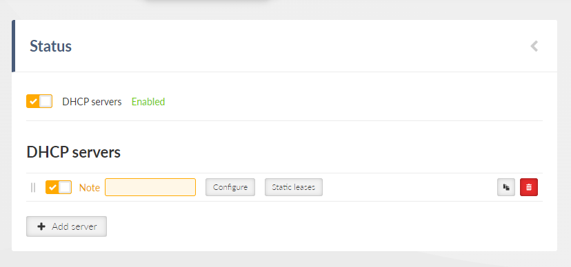
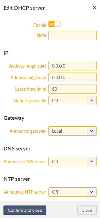
- Enable
{Enable; Disable}, default = “Enable”
Enables the currently selected DHCP server.
- Note
Informational note.
- Address range start
IP address, default = 0.0.0.0
The start of the range of IP addresses allocated. It must be the case that Address range start <= Address range end.
Address must be in the address range of the ETH, LAN, VLAN, or Wi-Fi interface.
- Address range end
IP address, default = 0.0.0.0
The end of the range of IP addresses allocated. It must be the case that Address range start <= Address range end.
Address must be in the address range of the ETH, LAN, VLAN, or Wi-Fi interface.
Note The ranges of active DHCP servers must not overlap.
- Lease time [min]
Number {2 – 10080}, default = 60
Address lease period. It is applied to both dynamic and static addresses.
- Static leases only
List box {Off; On}, default = “Off”
Specifies whether the range is used only for allocating fixed (static) addresses. If enabled, it must be in the Static Leases table.
- Announce gateway
List box {Off; Local; Manual}, default = “Local”
Configures the announcing of the router to clients.
Off: Gateway is not announced.
Local: The router’s IP is announced as a gateway.
Manual: Manually set IP address is announced as a gateway.
- Gateway address
IP address, default = 0.0.0.0
The IP address of the gateway being announced.
- Announce DNS
List box {Off; Local; Manual}, default = “Local”
Configures the announcing of the DNS server to clients.
Off: DNS server is not announced.
Local: The router’s IP is announced as a DNS server. Only if DNS forwarding is enabled.
Manual: Manually set IP address is announced as a DNS server.
- Primary DNS server
IP address, default = 0.0.0.0
The IP address of the primary DNS server being announced.
- Set secondary DNS server
List box {Off; On}, default = “Off”
Determines if the secondary DNS server is announced.
- Secondary DNS server
IP address, default = 0.0.0.0
The IP address of the secondary DNS server being announced.
- Announce NTP server
List box {Off; Local; Manual}, default = “Off”
Configures the announcing of the NTP server to clients.
Off: NTP server is not announced.
Local: The router’s IP is announced as an NTP server.
Manual: Manually set IP address is announced as an NTP server.
- NTP server
IP address, default = 0.0.0.0
The IP address of the NTP server being announced.
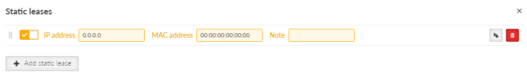
Each line defines a static assignment of a fixed IP address to the client based on the MAC address.
- Enable
Listbox {Enable; Disable}, default = “Enable”
Enables/Disables selected line.
- IP address
IP address, default = 0.0.0.0
The fixed IP address assigned to the client.
Must be unique in the Static Leases table.
Must belong to the parent range in the DHCP Servers table.
It must not conflict with the local station address.
- MAC address
MAC address, default = 00:00:00:00:00:00
The MAC address of the client for which the fixed IP address is assigned.
Must be unique in the Static Leases table.
- Note
Informational note.
DNS forwarding functions as a DNS proxy server. Receives DNS queries from clients on selected interfaces. Filters queries. Translation of selected names can be blocked. Sends custom queries to a specified list of servers. Maintains a cache from which the client can respond immediately without querying parent servers.
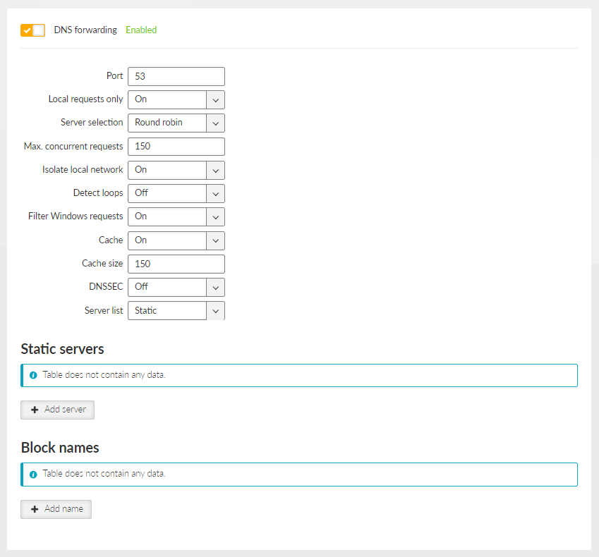
- Enable
Listbox {Enable; Disable}, default = “Enable”
Enables/Disables DNS forwarding.
- Port
Number {1 – 65535}, default = 53
The port number (both UDP and TCP) on which the server listens for client requests.
- Local requests only
Listbox {Off; On}, default = “On”
Determines if the server only serves requests from addresses on the local network (from addresses in ranges set on the interfaces). Requests from other addresses will be rejected.
- Server selection
List box {Round robin; Strict order; All simultaneously}, default = “Round robin”
Sets how servers are selected for the query.
- Round robin
Selects servers one by one, preferring those that answered.
- Strict order
Always starts with the first server in the list, and tries the next in the sequence if it fails.
- All simultaneously
The request is sent to all servers at the same time and the first response is awaited.
- Max. concurrent requests
Number {5 – 250}, default = 150
The maximum number of DNS requests running simultaneously.
- Isolate local network
Listbox {Off; On}, default = “On”
Determines whether the server isolates the local network. If enabled, it blocks forcing translation of local addresses from parent servers, it does not send reverse queries to private addresses to parent servers.
- Detect loops
Listbox {Off; On}, default = “Off”
Enables loop detection between DNS servers.
- Filter Windows requests
Listbox {Off; On}, default = “On”
Filters periodic DNS requests generated by Windows.
- Cache
Listbox {Off; On}, default = “On”
Enables cache responses to DNS requests. If the response to the client request is cached, it is returned immediately and there is no need to make further requests to the parent servers.
- Cache size
Number {50 – 10000}, default = 150
Maximum number of entries in the cache.
- DNSSEC
Listbox {Off; On}, default = “Off”
Enables authentication of responses from parent servers using DNSSEC and chain of trust (DNS trust anchors table).
- Server list
Listbox {Static; Dynamic}, default = “Static”
- Static
Static list of servers in the Static servers table.
- Dynamic
Listbox {WWAN (MAIN); WWAN (EXT); PPP 1; PPP 2; PPP 3; PPPoE client}, default = “PPPoE client”
The list of servers is obtained from the dynamic WAN interface parameters. The corresponding interface must be active.
The rows define the addresses of the parent DNS servers in the static list.
The maximum number of DNS servers is 32.
Active only if Server list is set to Static.
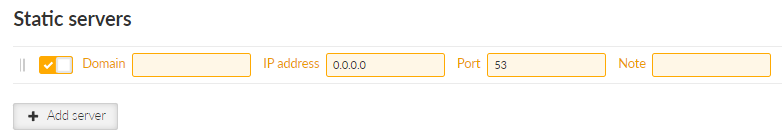
- Enable
Listbox {Enable; Disable}, default = “Enable”
Enables/Disables selected line.
- Domain
String {0–128 char}, default = <empty>
Domain name.
- IP address
IP address, default = 0.0.0.0
IP address of the static server.
- Port
Number {1 – 65535}, default = 53
The destination port on which the server listens for DNS requests.
- Note
Informational note.
Each line defines DNS names whose translation is blocked.
The maximum number of blocked names is 128. The order does not matter.
- Enable
Listbox {Enable; Disable}, default = “Enable”
Enables/Disables selected line.
- Domain
String {0–128 char}, default = “example.com”
Domain name, which translation to the address will be blocked.
- Note
Informational note.
Each line defines a DNSSEC Trust Anchor.
The maximum number of DNSSEC Trust Anchors is 8. The order does not matter.
Active only if Cache and DNSSEC are turned On.
- Enable
Listbox {Enable; Disable}, default = “Enable”
Enables/Disables selected line.
- Key tag
Number {0 – 65535}, default = 0
Key identifier. Must be unique among the active lines in the table.
- Algorithm
Number {0 – 255}, default = 0
Key algorithm identifier.
- Digest type
Number {0 – 255}, default = 0
Key digest algorithm identifier.
- Digest
Hexadecimal string, default = <empty>
Digest (hash) key.
- Note
Informational note.
SNMP (Simple Network Management Protocol) implementation in M!DGE3 provides three SNMP versions: v1, v2c and v3.
| Note | |
|---|---|
Following characters are prohibited in SNMP communication: |
- SNMP mode
List box {Off; v1_v2c_v3; v3}, default = “Off”
Enables the SNMP and defines which protocol versions are available.
- Community name
String {1–32 char}, default = “public”
Community name used by v1 and v2c. When mode v1_v2c_v3 is used, this parameter is mandatory.
Version 3 settings
- Security username
String {1–32 char}, default = <empty>
Username for SNMPv3. When v3 protocol is selected, this parameter is mandatory.
- Security level
List box {NoAuthNoPriv; AuthNoPriv; AuthPriv}, default = “NoAuthNoPriv”
The v3 protocol security level. Switches on/off Authentication (Auth) and the SNMP data encryption (Priv).
- Authentication
List box {MD5_legacy; SHA1_legacy; SHA224; SHA256; SHA384; SHA512}, default = “SHA256”
Authentication algorithm. Legacy algorithms are not recommended to use, they are available for compatibility reasons only.
- Authentication passphrase
String {8–128 char}, default = <empty>
Passphrase used for authentication with SNMP server.
- Encryption
List box {DES_legacy; AES128; AES192; AES256}, default = “AES128”
Encryption algorithm.
- Encryption passphrase
String {8–128 char}
Passphrase used for data encryption when communicating with SNMP server.
- Engine ID mode
List box {Default; User defined}, default = “Default”
Engine ID serves for unique identification of the SNMP instance (i.e. the M!DGE3 unit) according to RFC3411. When the “Default” Engine ID mode is selected the MAC address of the ETH1 interface is used for the unique part of the Engine ID (the whole Engine ID example: 800083130302a92006ef).
- Engine ID
String {1–27 char}
When “User defined” Engine ID mode is selected the differentiated part of the Engine ID can be entered as ASCII characters or generated (e.g. U3qPrisWoDYbBVNsAWluZYGL3M5). This string is converted into HEX number (i.e. 55 33 71 50 72 69 73 57 6f 44 59 62 42 56 4e 73 41 57 6c 75 5a 59 47 4c 33 4d 35). The whole Engine ID for mentioned example: 800083130455337150726973576f44596242564e7341576c755a59474c334d35.
Notification
Notification is used for asynchronous notification from a M!DGE3 unit into the SNMP server.
- Notification mode
List box {Off; Trap; Inform}, default = “Off”
Mode of notification; Inform is not supported by SNMPv1.
- Notification version
List box {v1; v2c; v3}, default = “v2c”
Notification packets version.
- Inform repeats
Number {0 – 10}, default = 3
Number of repeats used when Inform acknowledge was not received.
- Inform timeout [s]
Number {1 – 20}, default = 10
Inform acknowledge timeout.
Notification destinations
- Destination IP
IP address, default = 0.0.0.0
IP address of SNMP server receiving notification packets.
- Destination port
Number {1 – 65535}, default = 162
Notification packets destination port.
For more detailed information, please see SNMP application note.
Syslog enables logging of events on a remote server. Syslog messages are created in the unit in accordance with RFC5424 and sent to a remote server. Messages can be sent using UDP or TCP.
New system logs and events start to be sent to the remote server after the station boots. Incase of unavailability of the remote server, the logs are stored in the disk buffer and sent to the remote server after re-establishing a connection with it.
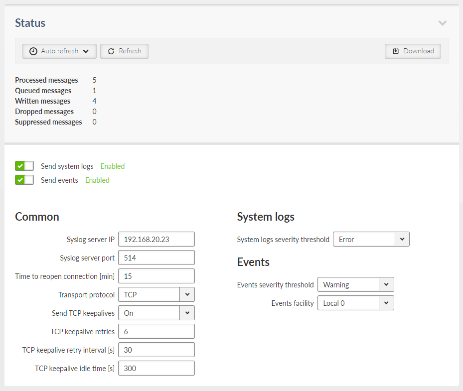
- Send system logs
{Enable; Disable}, default = “Disable”
Activates/Deactivates sending of system logs to the remote server
- Send events
{Enable; Disable}, default = “Disable”
Activates/Deactivates sending of system events to the remote server
Common
- Syslog server IP
IP address, default = 0.0.0.0
IP address of the remote syslog server
- Syslog server port
Number {1 – 65535}, default = 514
Syslog remote server port number
- Time to reopen connection [min]
Number {1 – 240}, default = 15
Time (in minutes) to wait to retry of the connection to the remote server when the connection was closed
- Transport protocol
List box {UDP; TCP}, default = “UDP”
Type of the protocol for the data transport
When TCP:
- Send TCP keepalives
List box {Off; On}, default = “On”
Switches On/Off sending of the TCP keepalives messages
- TCP keepalive retries
Number {1 – 15}, default = 6
Number of keepalive retries when the reply was not received.
- TCP keepalive retry interval [s]
Number {10 – 240}, default = 30
The interval (in seconds) at which a TCP keepalive message is re-sent if no response is received.
- TCP keepalive idle time [s]
Number {60 – 64800}, default = 300
Connection inactivity time (in seconds) waiting for the TCP keepalive message to be sent.
System logs
- System logs severity threshold
List box {Emergency; Alert; Critical; Error}, default = “Emergency”
System messages with this and higher severities will be sent to the remote server. Messages with lower severities will not be sent.
Events
- Events severity threshold
List box {Emergency; Alert; Critical; Error; Warning; Notice; Informational}, default = “Emergency”
System events with this and higher severities will be sent to the remote server. Events with lower severities will not be sent.
- Events facility
List box {Local 0; Local 1; Local 2; Local 3; Local 4; Local 5; Local 6; Local 7}, default = “Local 7”
Classification of system events into facilities as per RFC 5424 for local use: Local 0 to Local 7 (numerical codes 16 to 23) can be set. Consult with your Syslog server administrator about which facility will be used for individual groups of units.
M!DGE3, fully connected into the cellular network (status CONNECTED), is capable of receiving and sending SMS.
Receiving and sending SMS is provided by a linux service.
The queue of SMS waiting for sending is controlled by appropriate diagnostic linux service.
The length of the SMS depends on the type of module and coding. If longer SMS is required (only SMS notifications), it is divided into a Chained SMS.
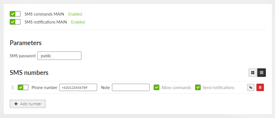
| Note | |
|---|---|
This section closely cooperates with Section 7.1.4, “Cellular”. |
- SMS commands MAIN/EXT
{Enable; Disable}, default = “Disable”
Enables / Disables SMS commands for Cellular MAIN/EXT. When enabled, the software module allows all incoming SMS and proceeds to initiate commands.
To process an SMS command from a phone number:
The specific phone number must be defined in parameter SMS numbers. If the phone number is not defined, the SMS will be not processed.
The SMS must contain a passphrase to pass the authentication (parameter SMS passphrase).
The SMS must contain a valid format of a command.
Only regular SMS are supported (Chained SMS are not).
Some commands generate an automatic reply, which is sent to a defined phone number(s), if this feature is enabled.
If this parameter is disabled, all incoming SMS will be deleted.
- SMS notifications MAIN/EXT
{Enable; Disable}, default = “Disable”
Enables / Disables SMS commands for Cellular MAIN/EXT.
When enabled, any change (if configured in Section 7.6.3, “Events”) will generate a notification SMS, which will be sent to all defined phone numbers with active notification.
To send an SMS notification to a phone number:
The specific phone number must be defined in parameter SMS numbers. If the phone number is not defined, it will not receive any notification.
Chained SMS are supported.
Sending SMS notifications can be activated in Section 7.6.3, “Events”.
- SMS passphrase
String {2–16 ASCII char}, default = “public”
Sets an SMS passphrase, which serves as an authentication to send SMS from defined phone number(s). The range of length of the passphrase is between 2–16 characters. SMS passphrase must not contain any unsupported characters. Unsupported characters are: “, `, \, $, ;.
- Phone number
{Enable; Disable}, default = “Enable”
Enables / Disables phone number. When enabled, defined phone number can either send or receive (or both) SMS. Amount of phone numbers, which can receive and send SMS is limited to 10.
- Note
Optional comment.
- Allow commands
{On; Off}, default = “On”
Allows to accept commands from defined phone number.
Note This parameter will work only if parameter SMS commands MAIN/EXT is enabled.
- Send notifications
{On; Off}, default = “On”
Allows to send notifications to defined phone number.
Note This parameter will work only if parameter SMS notifications MAIN/EXT is enabled.
All commands must match following format:
<passphrase>”space”<command>”space”[<param1>…]
SMS commands:
- cellstatus
Example: public cellstatus
Request for SMS with extract of Cellular status of the module, which received the SMS.
Reply of command “cellstatus”:
Station: <station_name>
<module_type> <SIM> Profile <profile_id>
Status: <connection_state>
Reg: <registration_state>
Net: <PLMN>
Svc: <service_type>
Band: <band>
Signal: <signal_strength>
APN: <username_APN>
IP: <assigned_IP>
Example of reply for command “cellstatus”:
Station: Alef
EXT SIM2 Profile 1
Status: CONNECTED
Reg: RegHome
Net: 23002
Svc: 2G_EDGE
Band: ARFCN 77
Signal: RSSI: >=-48 dBm
APN: internet
IP: 100.110.103.173
- smsevent <param>
Example: public smsevent raise
This command is used to turn on/off alarms which can be set in Section 7.6.3, “Events” by using its parameters (“raise”, “clear”).
This command does not generate an automatic reply.
GNSS server collects data from a GNSS (GPS) receiver and provides the data to potentially multiple client applications in a server-client application architecture. Internally is used by the NTP.
Data retrieval is possible using a gpsd client application (such as cgps or gpspipe). JSON data format is supported, and TPV, SKY, and PPS data frames are available.
- Enable GNSS
List box {On; Off}, default = Off
Enables / disables GNSS subsystem. This parameter occurs only, if GNSS module is available in the unit.
- Enable GNSS server – Advanced menu
List box {On; Off}, default = Off
Enables / disables GNSS server. This parameter can be set only, if parameter Enable GNSS server is set to “On”.
- GNSS server port
Number {1 – 65535}, default = 2947
Sets a TCP port number of the GNSS server. This parameter can be set only, if parameters Enable GNSS server and GNSS server port are set to “On”.
- Maximal GNSS downtime [min]
Number {1 – 65535}, default = 15
Sets a timer which counts for how long the unit does not need new data about location (when GNNS active). If the time runs out, security actions are triggered (linux service restart, module restart). This parameter can be set only, if parameter Enable GNSS server is set to “On”.
M!DGE3 introduces new concept for expert settings and rapid deployment of new features called “Advanced” section. Advanced section displays all configuration set points currently present in the device automatically, without need to design a special configuration page (like the ones in “Settings”). This allows us to deploy new features rapidly with each new firmware and also allows experienced users to fine-tune their M!DGE3.
Please note, that M!DGE3 is a very powerful device and it really shows all parameters in the Advanced section.
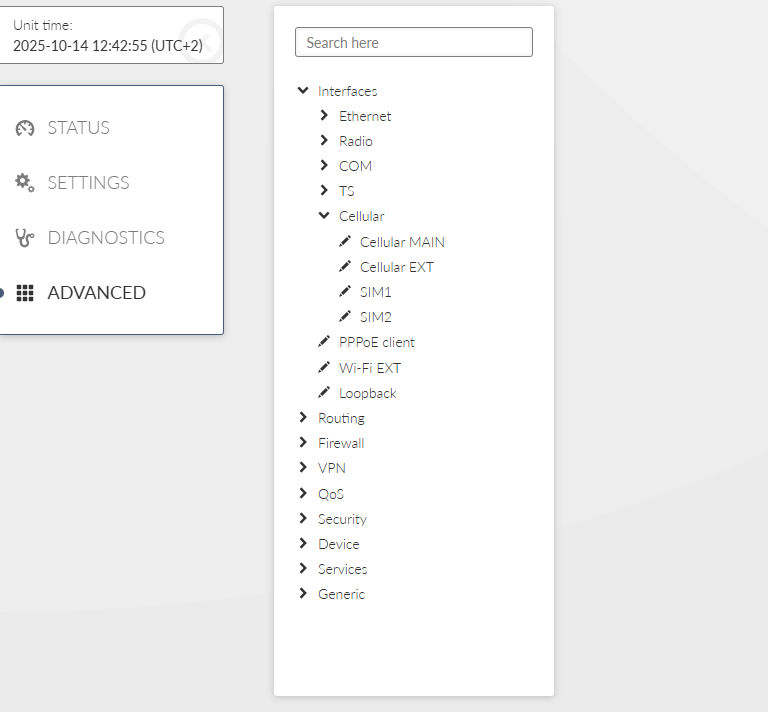
When you visit the page for the first time, you will see a search field and below a tree of configuration pages.
Search field looks through all labels and the tree itself and is capable of showing all relevant configuration pages. It features so called “fuzzy” search capable of returning right answers even when there is a typo in search query. Try searching for “Ethernet” or “BGP” to see the feature in action. To use the whole tree again, simply delete search query.
Configuration tree has two parts. For your convenience first few items (Interfaces, Routing, …) use similar hierarchy to “Settings”, but include all advanced settings. The newest features then can be found in the last item called “Generic”, which contains all configuration tables there are in the unit.
By selecting a configuration page (marked with pencil icon) a window is shown on the right side of the screen containing selected configuration page set points. You can change settings and then send them to the device the same way you know from “Settings”.
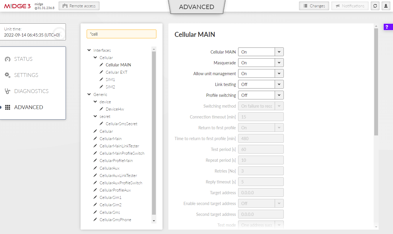
Be careful when adjusting settings in Advanced section and review the “Changes” page in detail before sending changes to the device.