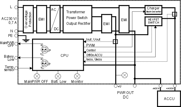
The power supply is a single-acting blocking converter (SELV) with two levels of output voltage. The lower level is for connecting supplied devices and the higher level is used for charging the back-up accumulator. The supply is protected on the input against shorting by safety fuse T4A. There is varistor protection against over-voltage on the primary side. The supply is short-circuit proof when powered by mains or from the accumulator. The supply is also resistant to over-voltage on the secondary side.
There is integrated management of charging and back-up in the MS2000, which is all independently controlled by a microprocessor. Microprocessor control allows charging of the battery to full capacity in least time with high efficiency (switch regulator on the secondary side) and maintains it in an optimal mode. Charging works in reference to ambient temperature (a sensor is located on battery terminals). Due to this the battery is protected against overload at higher temperatures. The voltage temperature coefficient on the lead-acid battery is generally 10 mV / °C. MS2000 is produced for using with lead-acid batteries 12 V / 12 Ah (24 V / 12 Ah), but by using the jumper on the front panel it is possible to change the maximum charging current even for another capacity for battery: 2–6 Ah (jumper left) or 6–12 Ah (jumper right). Another type of battery than lead-acid can be used but firmware should be adapted by the manufacturer.

The microprocessor controls connecting of the battery when there is a mains failure and disconnecting of the battery when the minimum manufacturer’s allowed voltage on the battery is reached (10.8 V or 21.6 V). An electronic switch also protects the supply with an electronic fuse against overload and surge current when connecting a capacitive load (of the order 6000 μF and larger). The electronic fuse disconnects the load after a capacitive overload and the MS2000 tries to connect the capacitive load again by PWM modulation with a smooth rise in voltage.
No current needs to be applied to PWR OUT for battery charge control to function correctly.
| Note | |
|---|---|
For MS2000 power supplies manufactured before 09/2008 a minimum current of 300 mA needs to be applied to PWR OUT for battery charge control to function correctly. |
Information about mains failure MAIN PWR OFF and information about low battery voltage BATTERY LOW, (e.g. there will be a total voltage failure for a connected device) is linked to the output terminal – open collector. The current through the output transistors is not limited in any way and therefore it is important to connect an external resistor in series with the transistor to limit the current to an acceptable level (the maximum current value is 0.5 A). The following table contains the value of current through the transistor, I_D, the output voltage when the transistor is switched on, U_DS, and the value of the external series resistors, R_s, for a 13.8 V and 24 V power supply.
| I_D[mA] | U_DS [mV] | R_s [Ω] | |
| Uvoltage 13.8 V | Uvoltage 24 V | ||
| 20.8 | 5.5 | 680 | 1200 |
| 89.1 | 24.5 | 150 | 270 |
| 471 | 137.5 | 27 | 56 |
The wires having the low battery voltage information are connected
between the screw connectors No.1
(BATTERY LOW) and 5 (GND), see the
diagram. The information MAIN POWER OFF is
given by wires connected to clamps No. 2
(MAIN PWR OFF) and 6 (GND) and it
is evaluated by function (m)isc (b)att using the
Setr utility, see the manual MORSE
firmware documentation.
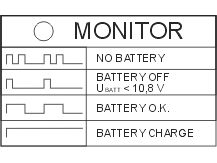
LEDs indicate the state of voltage on the power supply output (green LED PWR ON), mains failure (red LED MAIN PWR OFF), low battery voltage (orange LED BATTERY LOW). The last orange LED indicates the state of the battery charging cycle. The meaning of each state is shown on the front panel.
