The Settings menu is the same as on the Centre station except for the following:
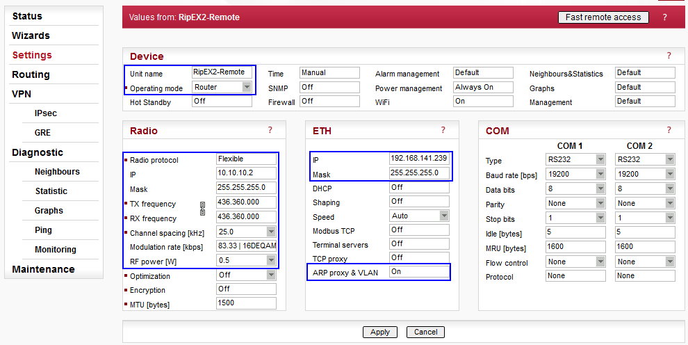
Unit name: RipEX2-Remote
Radio IP: 10.10.10.2/24
ETH IP: 192.168.141.239/24
ARP Proxy & VLAN: On
ARP Proxy & VLAN menu must be opened and configured. Set the Alias IP address for the Ethernet interface. We simulate several subnets behind local RipEX’s Ethernet (or SLIP protocol).
NOTE:
That is not necessary for GRE functionality; it
is just used to show this configuration option.
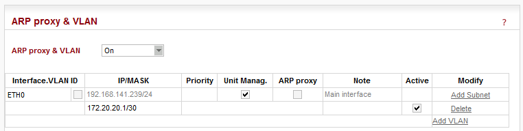
To set and enable this alias, you need to click on the “Add Subnet”
button and fill in the 172.20.20.1/30 subnet into the
“IP/MASK” field.
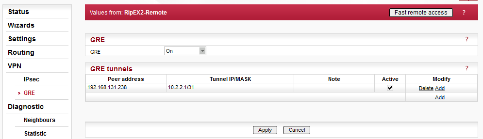
Set the Peer IP to the RipEX1-Base Ethernet IP address – 192.168.131.238. The GRE subnet must correspond to the Centre settings, i.e. choose the second IP address within a given subnet – 10.2.2.1/31.
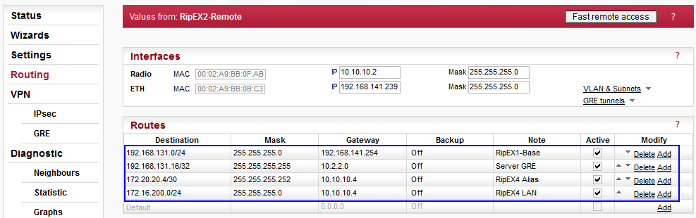
The last step is to configure Routing rules.
192.168.131.0/24, Gateway 192.168.141.254
This rule depends on your L3 infrastructure, but in our example, we use the rule to route data for 192.168.131.0/24 network via local gateway.
192.168.131.16/32, Gateway 10.2.2.0
The route using the GRE tunnel – packets for the Server (192.168.131.16) are encapsulated into the GRE. You might configure other destinations within this subnet if required, but not 192.168.131.238 (RipEX Ethernet – Peer IP, i.e. RipEX1-Base).
172.16.200.0/24 a 172.20.20.4/30, Gateway 10.10.10.4
Data for subnets behind RipEX4-Remote are routed to its 10.10.10.4 Radio IP address (i.e. not using GRE tunnel).