Check the M!DGE3 and RipEX2 manuals for detailed explanation of IPsec tunnel protocol and its parameters.
Within this application note, we will interconnect M!DGE3 units via IPsec tunnels utilizing multiple configuration options such as Tunnel vs. Transport mode, static and dynamic routing or firewall rules.
The examples build on each other, so it is recommended that you work through the material from the beginning to see a complete, step-by-step configuration guide.
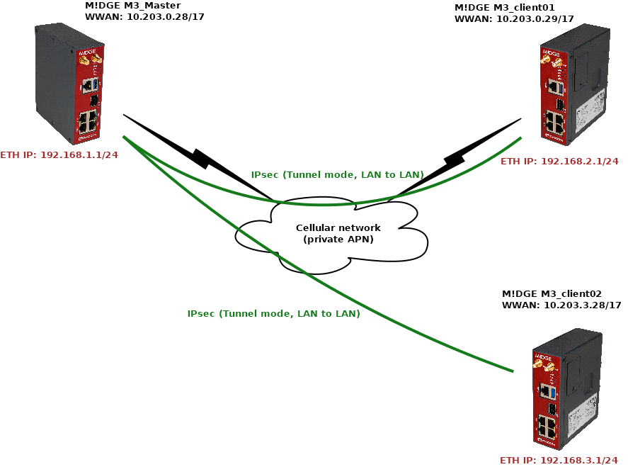
The most used mode in IPsec is a “Tunnel” mode which enables LANtoLAN communication among routers. In our example, we will connect M!DGE Master with two clients, each with unique LAN subnet for interconnection (Layer3).
Once the tunnel is established and working, any device behind the Master unit should be able to communicate with any device behind client routers, and vice versa.
| Note | |
|---|---|
IPsec itself cannot interconnect devices/routers with L2 “flat” topology. For such purpose, the easiest way is GRE L2, or encrypted option via OpenVPN bridged/tap option. |
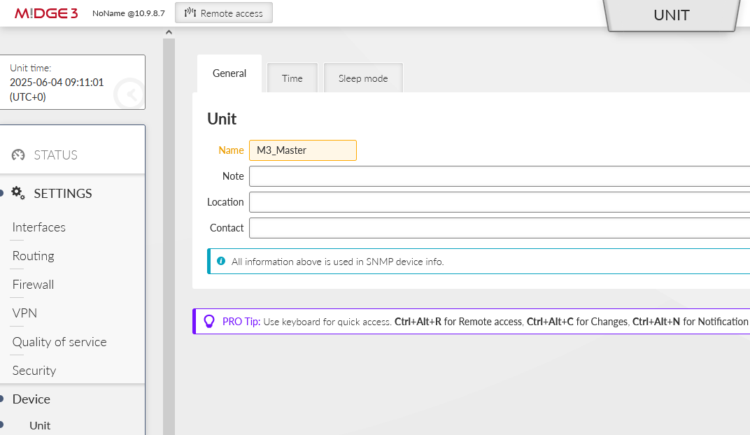
You can name the units to suit your needs. In this example, units are named:
M3_Master
M3_client01
M3_client02
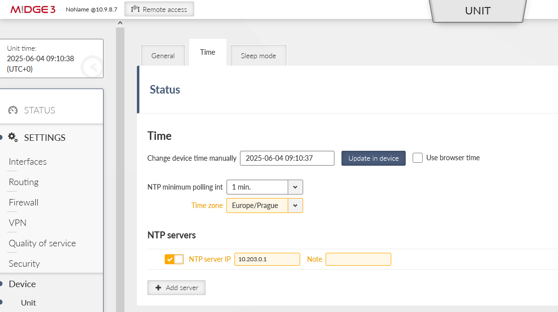
Especially for debugging purposes, we ensured there is correct time in our units via the NTP server.
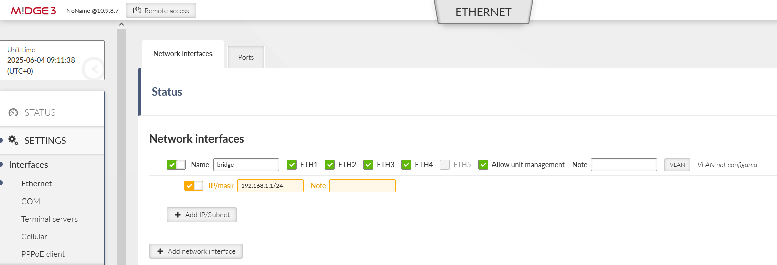
Go to the SETTINGS > Interfaces > Ethernet and change the “bridge” IP to 192.168.1.1/24.
Continue to the SETTINGS > Interfaces > Cellular and set up your cellular profile. Your configuration will be different compared to our settings, because each APN from any service provider will require its unique APN settings and you obtain different IP addresses. If testing, set this menu to match the APN requirements.
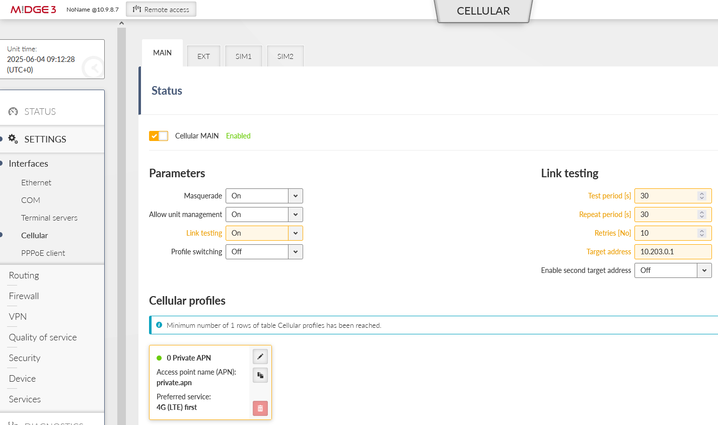
We periodically check the link via pinging our server 10.203.0.1 IP address every 30 seconds. This helps to ensure the connection stability and possible faster re-establishments in case of any connection issues.
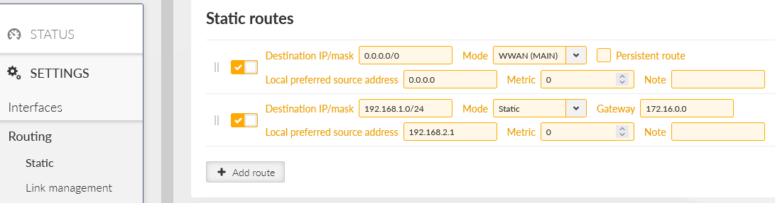
Go to the SETTINGS > Routing > Static and set at least one static route via our cellular interface.
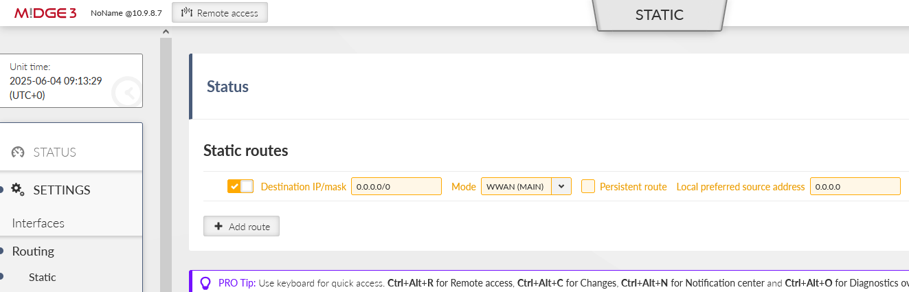
There is a default route (make sure you change the default mask from /32 to /0) via WWAN (MAIN) interface. In case you utilize the extension slot, the mode is WWAN (EXT). Without this route, there is no traffic being forwarded/sent out via the cellular interface.
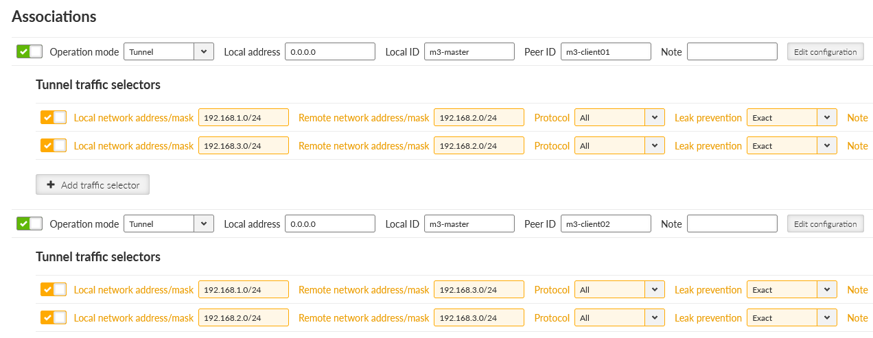
Now, the most last step is to configure IPsec tunnels. We need to create two tunnels, because we will connect this Master unit with both the clients. Go to the SETTINGS > VPN > IPsec menu and enable it.
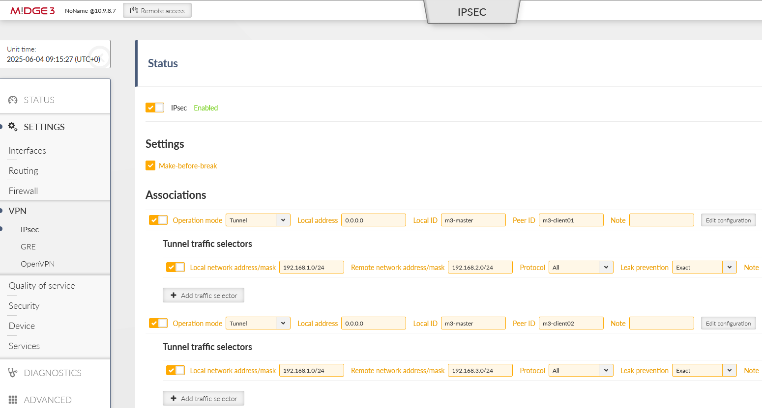
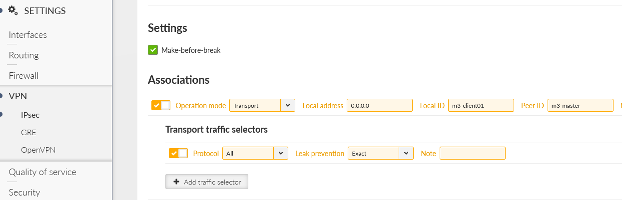
The option “Make-before-break” is also selected for better rekeying phases. Create two Associations in a Tunnel mode. Keep the Local address to be “dynamic” (set as 0.0.0.0) so we can utilize “any” cellular IP address obtained from the APN/operator.
| Note | |
|---|---|
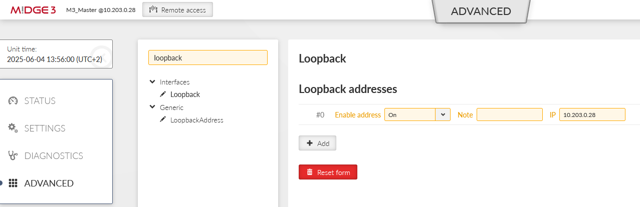
In case of static IPs, we can also configure a particular IP address. In our case, it is 10.203.0.28, but because this IP is not set/known during the configuration, you need to specify this IP not just in this parameter, but also in the ADVANCED menu via the “loopback” IP. Otherwise, the advanced configuration verification process will return an error. We will not utilize this option though. |
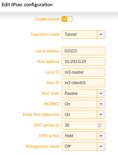
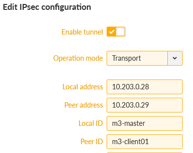
Local ID is set to “m3-master” and Remote ID is set to “m3-client01” for the 1st tunnel, and “m3-client02” for the 2nd tunnel.
Network selectors must match our LAN subnets depicted on the topology, i.e. 192.168.1.0/24 is our local LAN and 192.168.[2-3].0/24 are our remote LAN subnets.
Within the IPsec configuration details, set the “Start state” to Passive (clients will open the connections) and enable DPD with the “Hold” action. Last, but not least, configure the Passphrase for both tunnels. We used „racom123“.
Save the changes from the “Changes” menu (you can also validate them before really sending them into units).
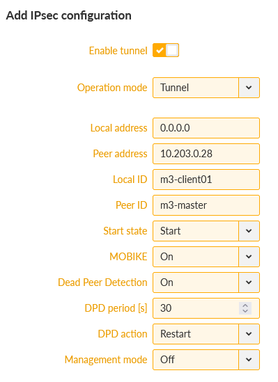
Clients’ setup is very the same. Set the correct Unit name, correct time settings, Ethernet IP/mask and Cellular profile.
Continue with the IPsec settings which must match the M3_Master settings, swapping the IDs. Set the DPD action to “restart”.
Do the corresponding changes to the M3_client02 unit as well.
Go to one of the menus to check the IPsec status:
SETTINGS > VPN > IPsec menu
DIAGNOSTICS > Information > VPN > IPsec
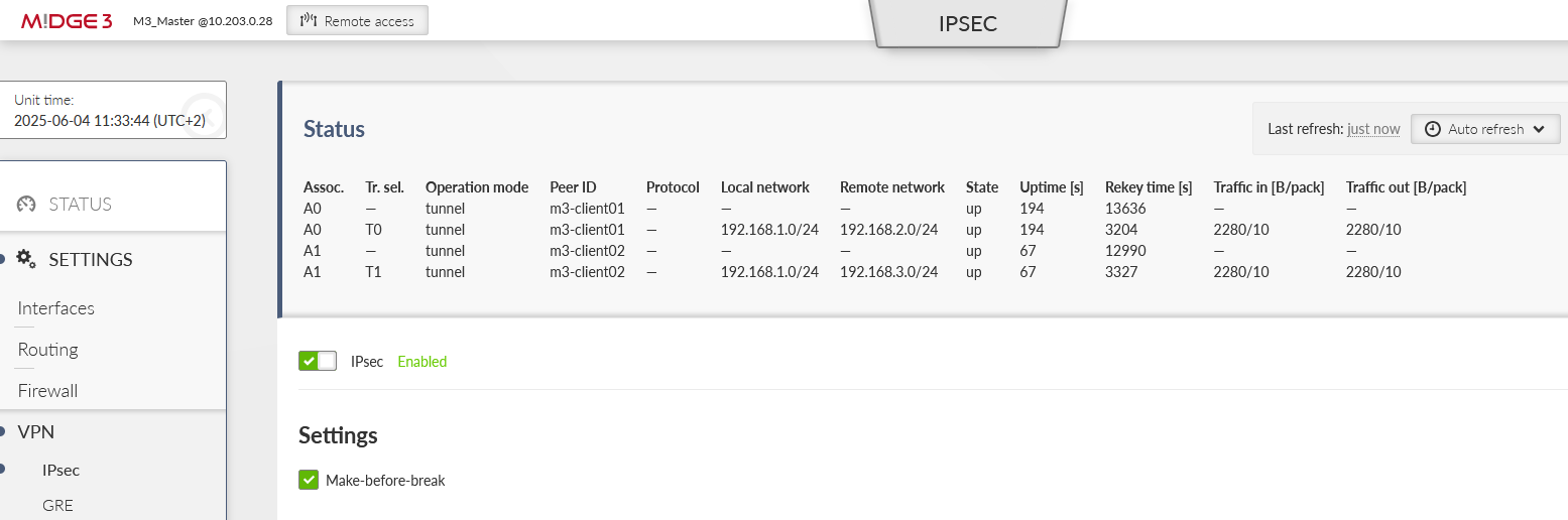
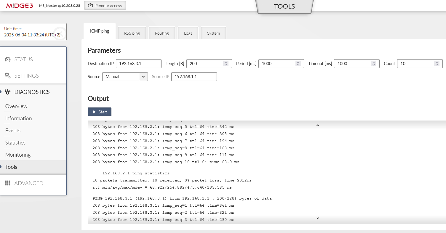
In correct settings, both tunnels should be “up” and e.g. the ICMP ping should be working between the Master units and both clients.
In case of any issues, you should double-check the configuration for mistakes (typos, …).
It is also possible to see the IPsec logs, go to the DIAGNOSTICS > Tools > Logs menu. Select the IPsec daemons and click on the “Start” button.
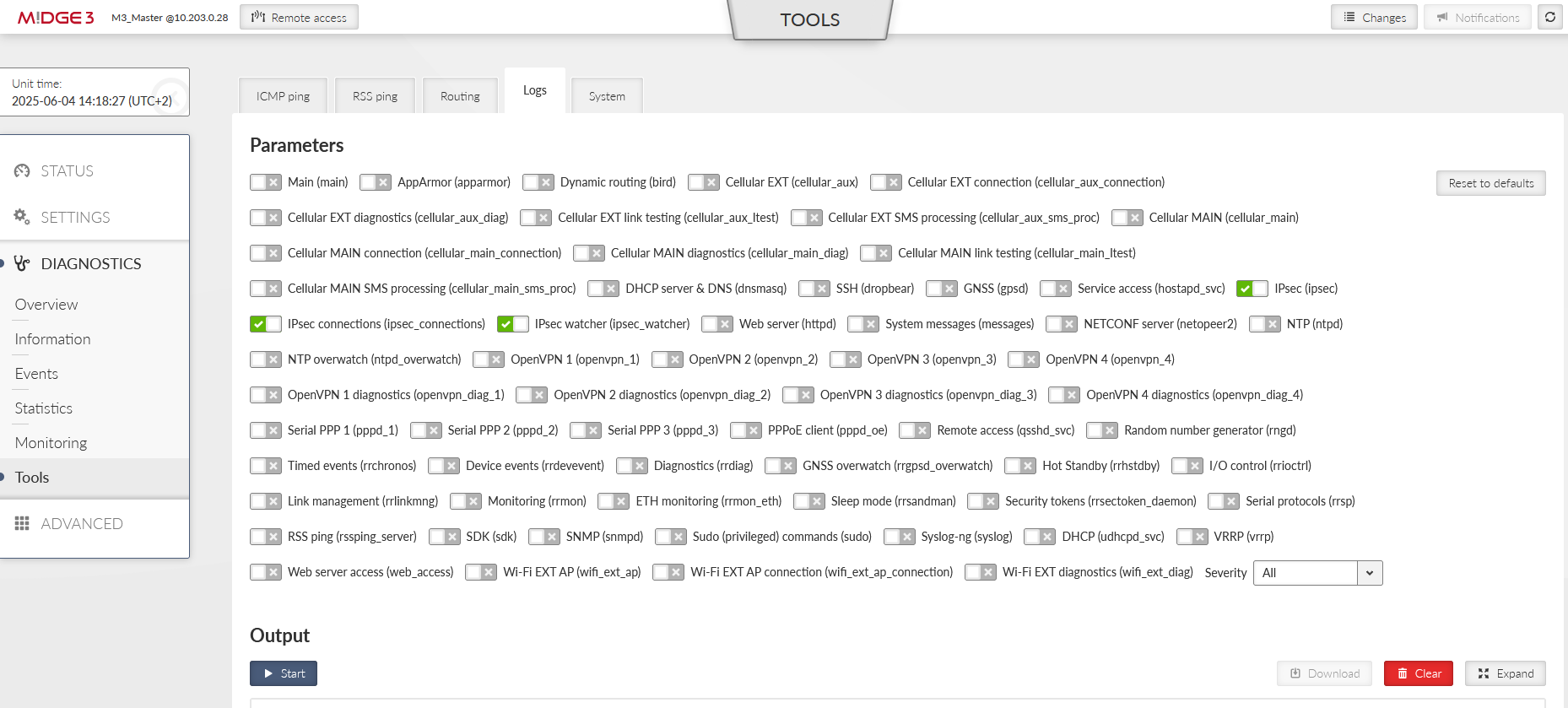
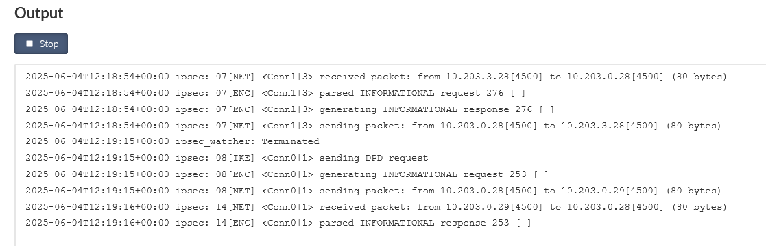
You may be informed about possible issues in the configuration/connections so you can find a fix sooner.
In our scenario, the communication between clients is not enabled/configured.
It is usually easier and more straightforward to enable client-to-client communication in the OpenVPN than in IPsec, especially with more clients and their networks.
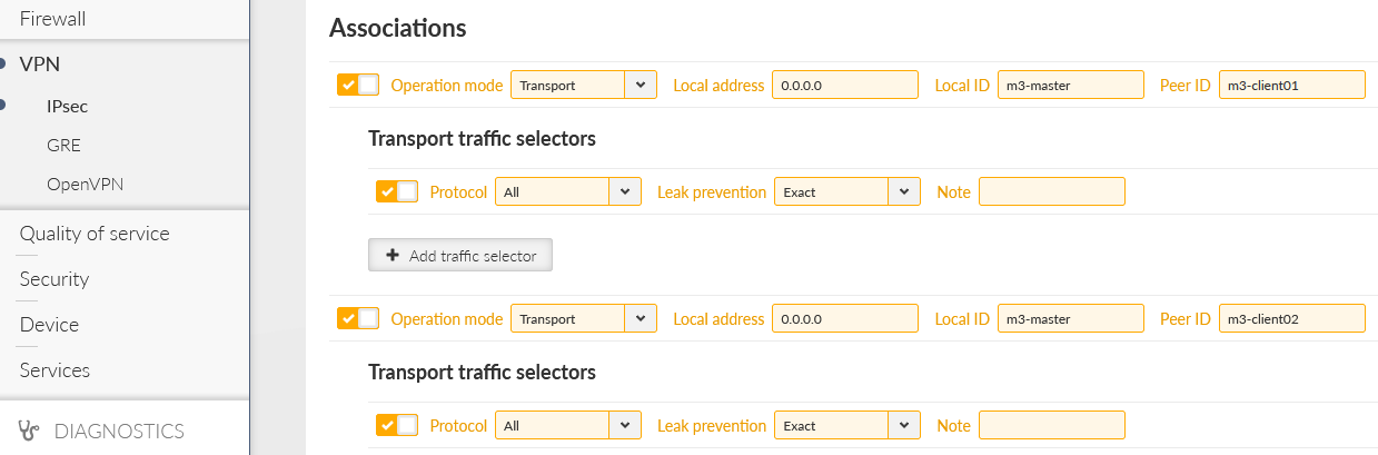
We need to add 2nd Traffic selectors in each IPsec tunnel configuration, enabling M3_client01 to/from M3_client02 LAN communication.
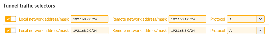
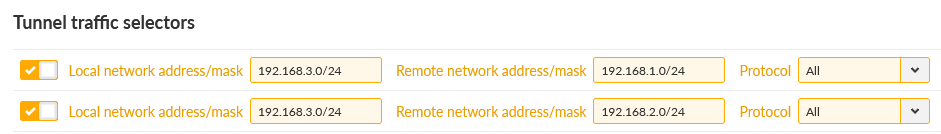
Be careful in setting correct direction of Traffic selectors (Local/Remote). As you can see, if utilizing e.g. 10 clients, it may be very complex settings in Traffic selectors, prone to errors/typos. Thus, we suggest OpenVPN for such communication scheme.
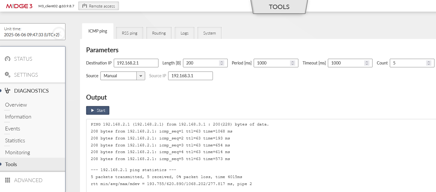
You can test the accessibility e.g. via the ICMP ping tool.
Since the FW 2.2.4.0, expanded IPsec Traffic selector settings to include the ability to choose a method for creating automatic rules against traffic leakage (possibility of interaction with Policy filters on the Firewall) have been supported.
With each Traffic selector, within the IPsec tunnel, we add automatic L3 firewall rules (iptables). This creation can now be optimized. Options control the level of automatic protection against leaking or receiving unencrypted traffic.Check the manual for Leak prevention options supported and how the firewall rules could be created manually. See section Transport/Tunnel Traffic selectors in user manual.
Let us check the default “Exact” option firewall rules now, with current IPsec settings and “client-to-client” communication configured as well.
In the M3_Master unit, go to the DIAGNOSTICS > Information > Firewall > L3 menu and open/refresh the Status. Check the “*_ipsec” chains (forward_ipsec, input_ipsec, output_ipsec).
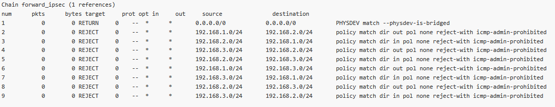
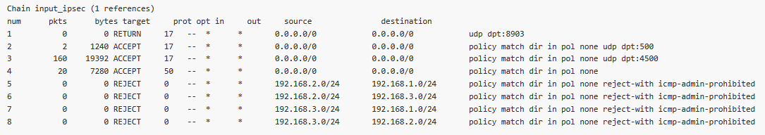
You can also see several automatic rules within Input and Output chains for UDP ports 500/4500 and protocol 50 so the IPsec could be established in case the firewall is already configured to block unwanted traffic. The other rules are there due to Traffic selectors.
Forward – two rules for each CHILD_SA (8 rules in our example)
Input – one rule for each CHILD_SA (4 rules in our example)
Output – one rule for each CHILD_A (4 rules in our example)
Especially notice the Output rules here – the Source is also filtered to match the Traffic selectors “Local network address/mask” options. This is due to the “Leak prevention” option is set to “Exact”.
Without these rules, sending or receiving traffic to be encrypted as unencrypted, would not be blocked – which is a security issue. Always have such rules in your network – Exact, Paranoid or set manually completely.
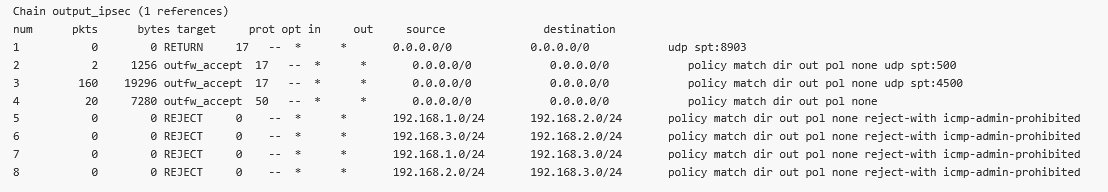
Let us switch to the older “Paranoid” option to see the differences. Do it in all three units for every CHILD_SA, i.e. Traffic selectors. E.g., do it four times in the M3_Master unit.
Check the updated firewall rules in the “Output_ipsec” chain.
As you can see, the Source IP/mask are not all set to 0.0.0.0./0. This is not wrong, but could block some traffic from different Source subnet other than the one configured within the IPsec settings.
Consider yourself if you prefer the Exact or Paranoid options.
You can also set the “Leak prevention” option to “Off” and configure the rules manually within the SETTING > Firewall > L3 menu. Replicate, or optimize the rules as required. You can use the Policy filter to match the automatic rules – the only small difference is that you cannot set the action to “Reject traffic with ICMP admin prohibited messages”, but just Deny (drop) such traffic.
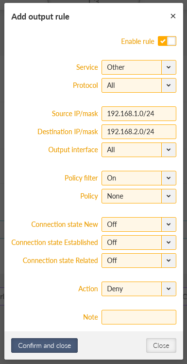
Within the example above, we deny all unencrypted traffic outgoing from M3_Master with Source IP within 192.168.1.0/24 and Destination IP within 192.168.2.0/24 (traffic to M3_client01). We only want to send this traffic encrypted.
You can do other three similar rules.
Feel free to combine the mentioned ways for optimized solution.
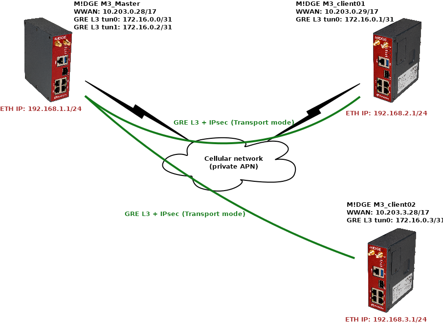
In a 2nd example, we will configure a transport mode instead of the Tunnel mode above. In Transport mode, only the payload of the original IP packet is encrypted and authenticated. The original IP header remains intact, allowing for direct routing, while the data itself is secured using the ESP protocol.
With IPsec, there are no new physical interfaces created, compared to GRE or OpenVPN. Thus, building any kind of dynamic routing over it or configuring various rules in Firewalls is not possible, or complex. In CISCO, it may even be required that GRE tunnels are combined with IPsec tunnels only in Transport mode (IPsec providing encryption, GRE providing routing options).
Within our example, we will switch from the Tunnel mode to the Transport mode. There will not be direct LANtoLAN routing via Traffic selectors anymore, but we will also configure the mentioned GRE L3 tunnels together with IPsec. First, we will configure static routing and then, we will change it to utilize dynamic routing instead (via Babel and BGP protocols).
First, go to the SETTINGS > VPN > IPsec menu and delete all Traffic selectors (the Tunnel CHILD_SAs). Then, switch both tunnels into the Transport mode and add one Transport Traffic selector to each. Keep them in default settings (Exact Leak prevention, All protocols).
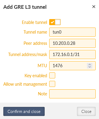
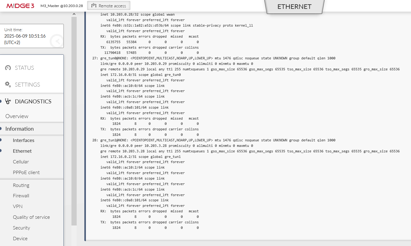
Now, go to the SETTINGS > VPN > GRE > L3 menu and create two new tunnels – one to each remote M3_client.
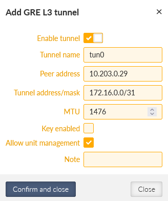
The 1st tunnel is pointing the M3_client01 Peer IP 10.203.0.29. It also creates a new “tun0” interface with IP 172.16.0.0/31 (the M3_client01 IP will be 172.16.0.1/31). In GRE, we can use /31 mask, because the connection is always just point-to-point, otherwise, we would need to use the /30 mask keeping the .0 address to the network and .3 to the broadcast.
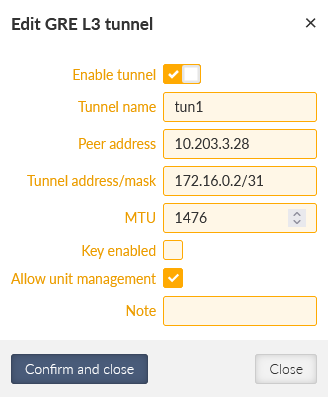
Add the 2nd tunnel with the 10.203.3.28 Peer address and 172.16.0.2/31 Tunnel address/mask (the M3_client02 IP will be 172.16.0.3/31). The tunnel name is “tun1”.
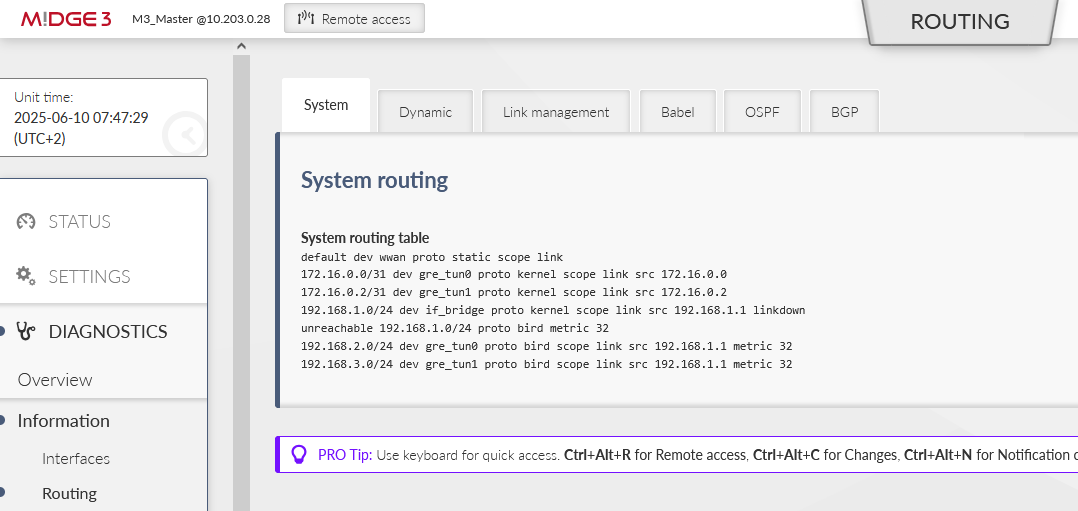
Last, but not least, go to the SETTINGS > Routing > Static menu. Add two new routes
192.168.2.0/24 via 172.16.0.1
192.168.3.0/24 via 172.16.0.3
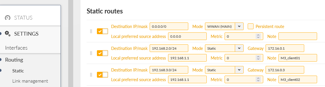
These two rules route the remote LAN subnet via the correct GRE L3 address (gateway) – all such traffic will be encapsulated into GRE and encrypted by IPsec. We also configured the Local preferred source address input field so the packets generated in M3_Master itself have the Source IP equal to its LAN IP, and not GRE or WWAN.
Check the prepared changes and save them.
Do the similar change in both the clients. Within SETTINGS > VPN > IPsec, delete the Tunnel traffic selectors, change the tunnel mode and add a new Transport Traffic selector.
Go to the GRE L3 menu and add one new tunnel back to M3_Master.
Add one routing rule back to the M3_Master.
| Note | |
|---|---|
We could set the route to 192.168.3.0/24 via 172.16.0.0 as well to have the client-to-client communication available. |
Do the corresponding changes in M3_client02 as well. Note to use the 172.16.0.2 IP address in the Static routing menu (correct GRE L3 IP address).
Save the changes in both units.
Check the accessibility e.g. via the ICMP ping from M3_Master to both the clients’ LAN IPs.
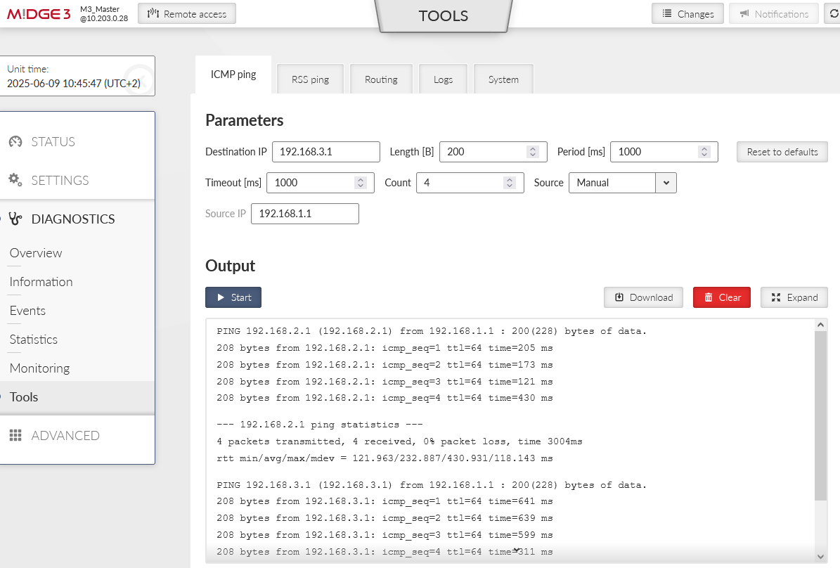
You can also open the 2nd window for the M3_Master unit’s Monitoring menu (DIAGNOSTICS > Monitoring). Enable monitoring of the WWAN MAIN interface and start the Monitoring feature. Run the ICMP ping tests again, to both clients from the 1st window.
You should see the ESP data (encrypted, IPsec).
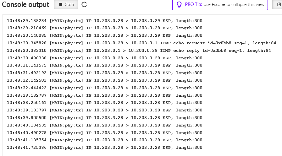
Within our output, we also see the Link Testing ICMP packets. Other data are encrypted.
In case of any issues, check your IPsec settings and its Status. You can also check the Logs from the IPsec daemons. You should also be able to see data in DIAGNOSTICS > Information > Interfaces > Ethernet for the particular GRE interfaces.
In case you enabled M3_client01 to M3_client02 routing as well (through the M3_Master), it should work as well.
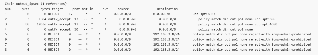
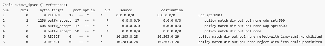
We can also check the automatic Traffic selectors rules. Let’s focus on the Output rules. The destination is correctly set to particular remote WWAN IP:
10.203.0.29/32 and 10.203.3.28/32
You may have noticed the Source is set to 0.0.0.0/0 even with the “Exact” Leak prevention. Why? The Local address is not set; we kept it to 0.0.0.0 so there is no known limit for the Source. It would be the same with the “Paranoid” option. If you want to filter it better, we can do it in two different approaches.
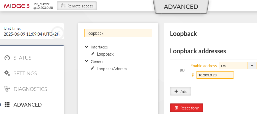
First is to define the Local address in the IPsec settings.
This is not the only change required. The local address must be known all times, but we receive our IP address on the WWAN interface in a dynamic matter. Go to the ADVANCED menu and create the “loopback” address with 10.203.0.28 address. This will not do any harm to our operation and enables us to define the Source address.
| Note | |
|---|---|
With a different APN, we remind you that you have completely different WWAN network and defined IP address do not match our settings (10.203.0.0/17). |
Go back to the DIAGNOSTICS > Information > Firewall > L3 menu and check the “ipsec_output” rules again.
A second approach could be setting the Leak prevention to “Off” and set the rules manually (with a “deny” action instead of ICMP prohibited).
Revert the changes from the 1st option. Go to the SETTINGS > VPN > IPsec menu and set the Leak prevention to “Off”.
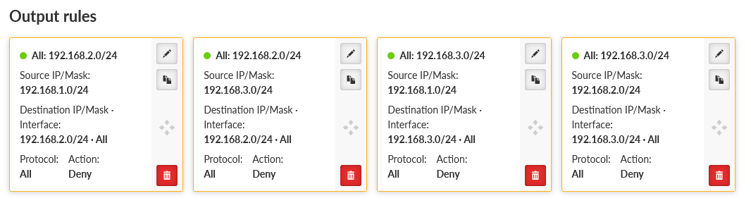
Go to the SETTINGS > Firewall > L3 menu. Enable the Output chain and create two rules to match the automatic rules.
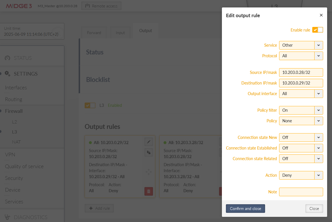
You would mimic the Input and Forward rules as well. We just focus on the Output now.
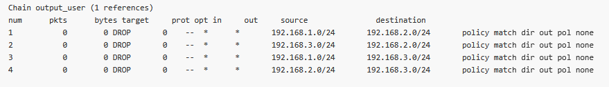
Once saved, double check the rules in DIAGNOSTICS > Information > Firewall menu again. Check the “output_user” chain.

Again, the choice is up to you so it matches your security requirements as much as possible.
In case static routing is not sufficient for your needs, you can also configure dynamic routing. There is already an application note for the Babel protocol.
This example will not cover advanced parameters of the protocol, check the mentioned app.note for details.
Go into M!DGE3 units and delete static routes to 192.168.[1-3].0/24 networks, keep the 0.0.0.0/0 route only.
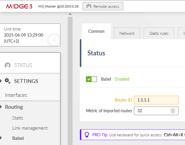
Go to the SETTINGS > Routing > Babel menu and enable it. Set the Router ID to 1.1.1.1.
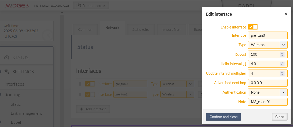
Switch to another tab “Network” and add two GRE L3 interfaces. The name is always with a prefix “gre_” followed by the interface name (“tun0” and “tun1”), i.e. “gre_tun0” and “gre_tun1”. The network is Wireless and you can set the Cost to 100. We also added a Note for better understanding.
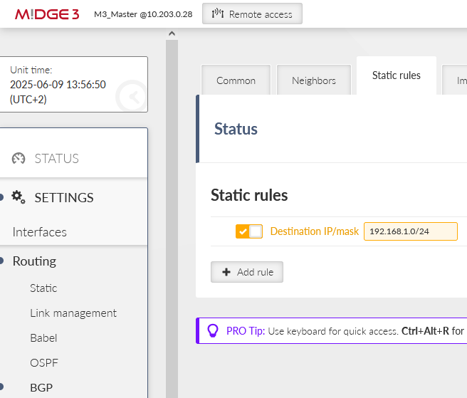
Open another tab “Static rules” and add a rule to propagate local LAN 192.168.1.0/24.
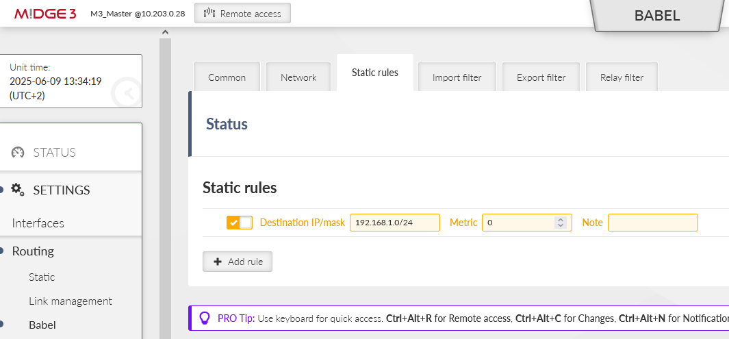
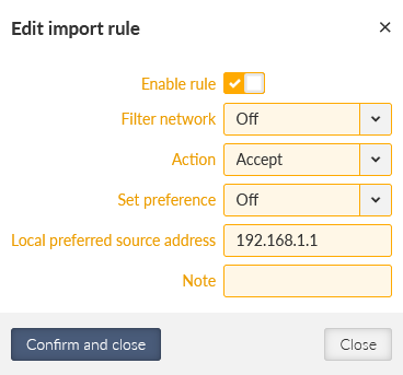
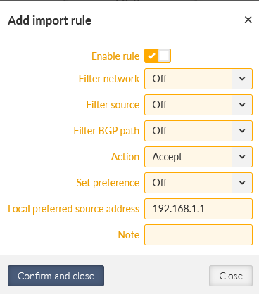
Go to the Import filter and add just one simple rule – keep it in default settings, but set the Local preferred source address to be our LAN IP 192.168.1.1.
Save the changes.
Set both the clients accordingly. Disable static rules and set the Babel:
M3_client01
Router ID 2.2.2.2
Network: gre_tun0, cost 100
Static rules: 192.168.2.0/24
Import filter: Local address 192.168.2.1
M3_client02
Router ID 3.3.3.3
Network: gre_tun0, cost 100
Static rules: 192.168.3.0/24
Import filter: Local address 192.168.3.1
Save the changes.
Use the mentioned application note if you encounter any issues.
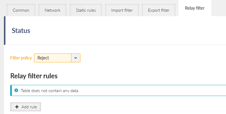
The last useful option is that we do not want our client units to be used as relays. In such a case, set the Relay filter action to “Reject”.
Once done, it is Master to clients and back communication, but also client to client – but always over the Master station.
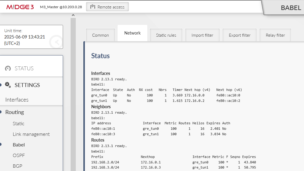
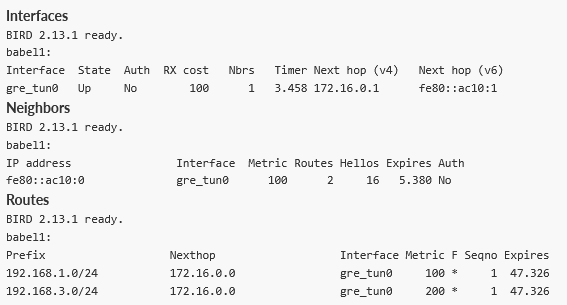
You can see the M3_client01 has a route to M3_client02 as well, but the cost is doubled – one hop to the Master and one hop to the 2nd client.
In case of more complex network topology, dynamic routing can be easily configured in each unit locally and the routing is done automatically (dynamically) within the network.
In case you have other devices in your network utilizing dynamic routing, it is possible to interconnect them with Babel as well, but very often BGP is preferred option for other routers. Our routers also support BGP. A simple and short example follows.
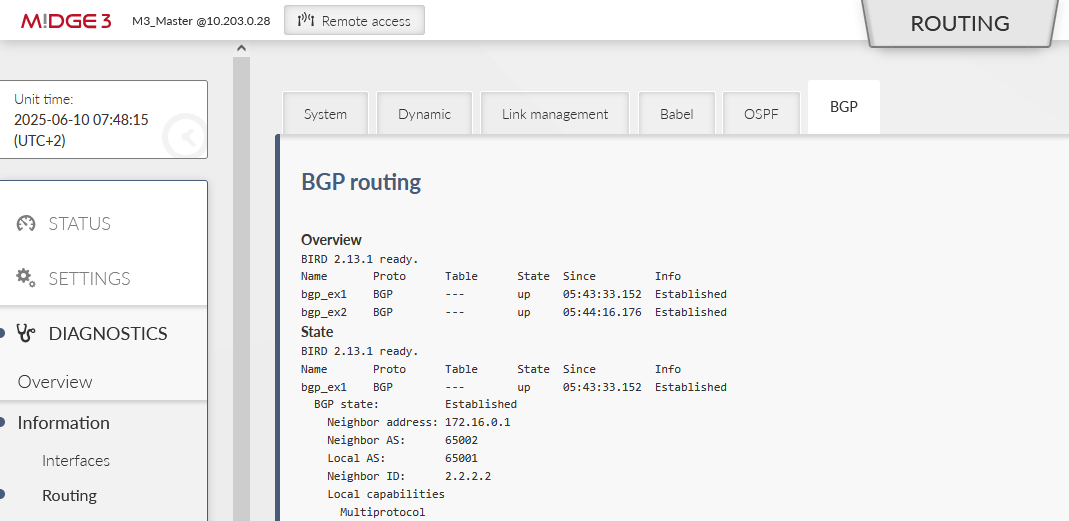
Turn off the Babel in all units and enable BGP within the SETTINGS > Routing > BGP menu. Set the same IDs as with Babel.
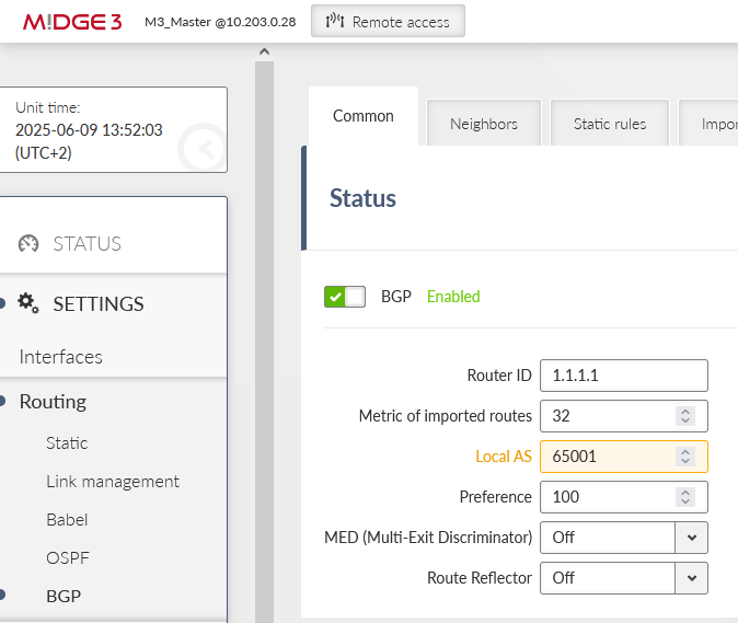
Note the changed Local AS 65001. The clients will have 65002 and 65003 AS numbers.
Go to the 2nd tab Neighbours and set both remote M!dge3 units here.
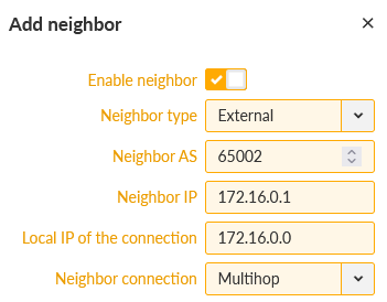
Keep the External type and set the Neighbor AS to 65002 and IP to 172.16.0.1. The local IP can stay 0.0.0.0 or you can manually set it to 172.16.0.0. The connection is usually “multihop” over the cellular network.
The 2nd Neighbor is M3_client02.
Within the next tab “Networks”, only set our local LAN 192.168.1.0/24.
Last, we also need to set the local preferred IP to be 192.168.1.1 (Import IGP filter tab).
Save the changes.
Do the corresponding changes in both clients.
M3_client01
BGP Router ID 2.2.2.2
Local AS 65002
Neighbor: AS 65001, IP 172.16.0.0
Local IP 172.16.0.1
Connection: multihop
Static rules: 192.168.2.0/24
Import IGP filter: Local preferred source address 192.168.2.1
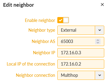
M3_client02
BGP Router ID 3.3.3.3
Local AS 65003
Neighbor: AS 65001, IP 172.16.0.2
Local IP 172.16.0.3
Connection: multihop
Static rules: 192.168.3.0/24
Import IGP filter: Local preferred source address 192.168.3.1