This document describes how to utilize RipEX radios to seamlessly upgrade or expand existing SCADA radio networks.
This upgrade or extension can be a gradual one-by-one replacement over a period of time or as a one-time project with no network outage.
No network outage.
No special expensive HW like migration station etc. required. Only standard RipEX radio modem is added to the existing base station and remote units are then replaced (added) one-by-one .
No time limits for legacy and new RipEX networks co-existence.
The same frequency for legacy and the new radio network can be used.
The same antenna for legacy and the new RipEX radio network can be used.
SCADA central SW and RTU’s can also be migrated, gradually and independently of each other or simultaneously. The new SCADA can be used simultaneously with the legacy one on another RipEX interface e.g. Ethernet. Central RipEX radio will then route packets for new RTU’s via new radio network.
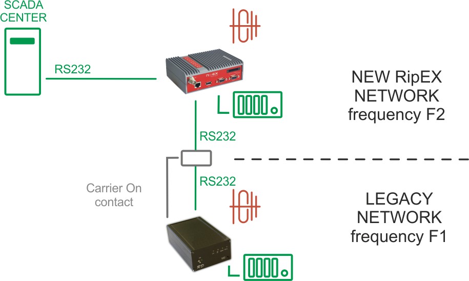
HW contact for “Carrier On” legacy base station transmissions supported.
All RipEX features e.g. unlimited number of repeaters on the way can be used in a new RipEX network.
Before you start migration, you should get the basic information about the legacy network:
Which SCADA Protocol is used (e.g. Modbus).
SCADA Protocol addresses of RTU’s on individual remote sites.
COM port settings of legacy radio modems on individual sites.
Which radio frequency is used.
Radio network topology and its possible optimization when RipEX will be used, e.g. repeater function.
Evaluate the next possibilities of usage of new RipEX features like integration of IP network into RipEX network, Terminal server as a new interface for SCADA etc.
This is the most common type of legacy SCADA network.
Master-slave polling, i.e. SCADA center (Master) sends requests one-by-one to RTU’s and waits for the response from polled RTU.
C24, Cactus, Comli, IEC101, ITT Flygt, Modbus RTU, RP570, DF1, DNP3, Siemens 3964(R), SLIP and UNI (can be used for any polling protocol with address byte(s) on fixed position) the same frequency for both, legacy and RipEX networks can be used.
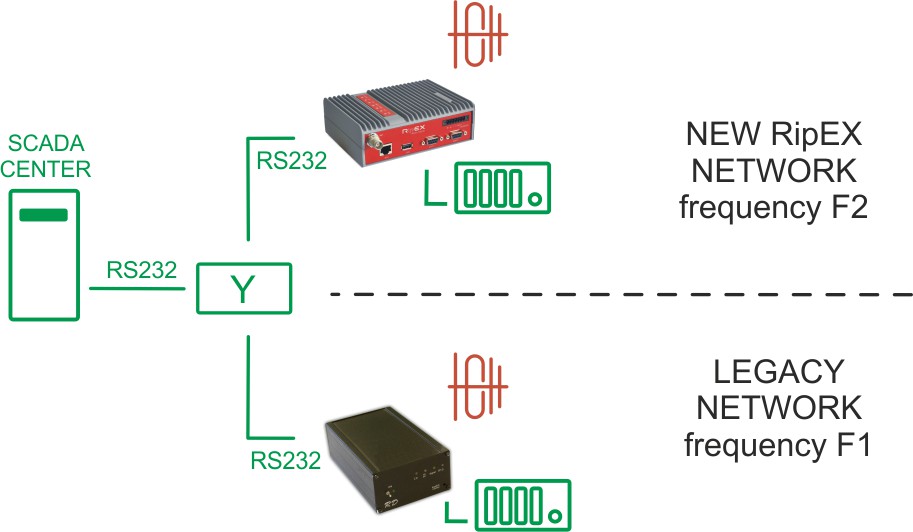
In such a case, RipEX in Router mode in centre/base station must be used. Packets coming from SCADA center (Master) are routed by RipEX based on SCADA Protocol address. When packet is directed to RTU in legacy network, it is routed to COM2, resp. to legacy radio modem and delivered via legacy radio network. Packets directed to RTU’s which are behind the RipEX network pass through the RipEX network. AAS (Automatic Antenna Switch, Part. No OTH-AAS) automatically disconnects radio modem while the other one is transmitting.
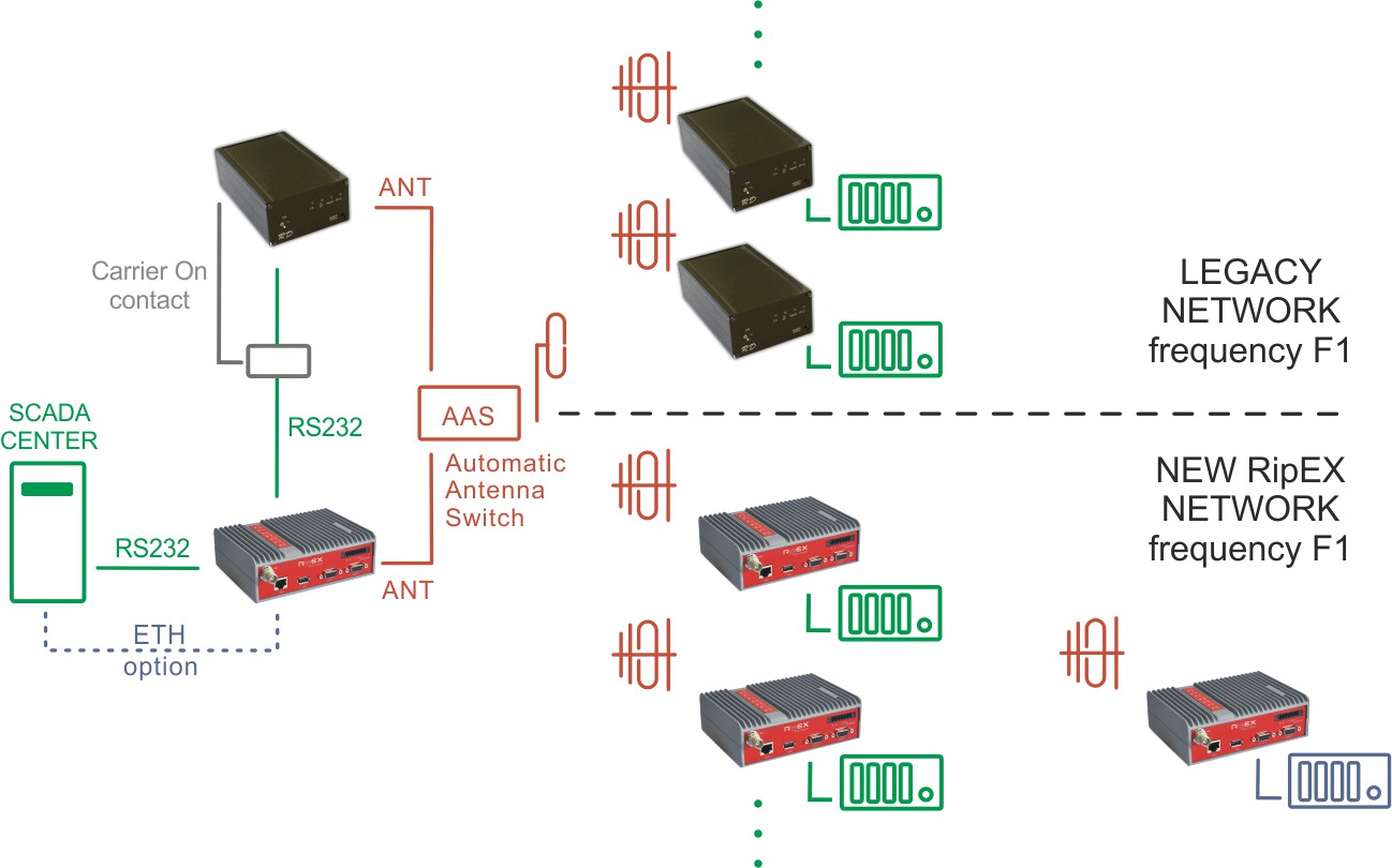
The original RS232 cable between SCADA Master and RipEX (COM1) is used. Note: RipEX is equipped with DB9F connector.
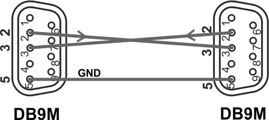
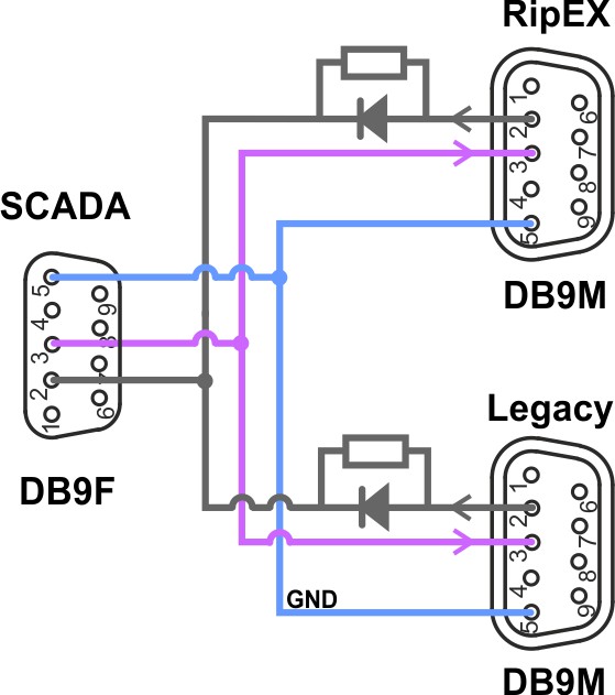
RS232 crosslink cable must be used for interconnecting of RipEX (COM2) and legacy radio modem (see Fig. 1.2, “RS232 crosslink cable” below). Note: It is equal which COM on RipEX is used for which connection.
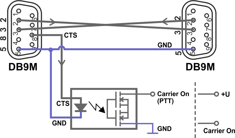
Legacy radio network uses different frequencies for Rx and Tx in most cases. Sometimes the base stations are duplex and Tx carrier is on all the time while SCADA center (Master) is sending/receiving the packets. Tx carrier is mostly controlled by separate HW signal from SCADA center (Master). RipEX also supports this feature when UNI protocol is used. CAB-MIG cable with simple SSR relay inside DB9 connector cover which is controlled by the CTS signal on COM is used for this. There is a possibility to set the upfront time when contact will be activated before the packets are transmitted.
| Note | |
|---|---|
User specific wiring can be utilized. |
| Note | |
|---|---|
All RipEX units must be defined with Radio IP addresses and must have the same Radio parameter settings e.g. frequency. |
The RipEX receives data from the SCADA centre via COM1 serial interface. This interface must be set accordingly (baud rate, stop bits, parity, etc.) – see the example below.
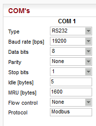
The Protocol must be chosen, e.g. Modbus. The Protocol needs to be set as a Master and an Address translation table must be configured for all RTU’s, either connected via legacy or new RipEX network. For Protocol address (e.g. Modbus) of RTU’s on sites connected via legacy radio network, set respective IP address equal to Radio IP of RipEX unit (in the example below, it is 10.10.10.254). For RTU’s connected via new RipEX network the IP addresses/ports correspond to respective RipEX Radio IP on respective remote site.
See the example:
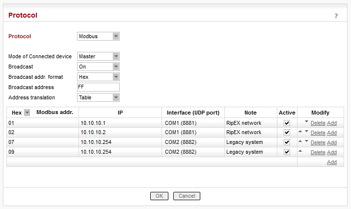
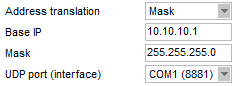
When the network finally consists of only RipEX radios, all these rules can be replaced with one simple Mask rule:
| Note | |
|---|---|
Whenever a new remote RipEX is deployed, Address translation Tables must be changed accordingly. |
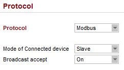
COM2 configuration is very simple. The same protocol (e.g. Modbus) must be set, but Mode of Connected device is set to Slave. No other settings are required.
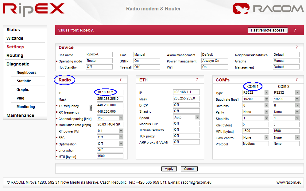
Remote radio configuration is straightforward. Once you configure the Radio parameters (must be the same as for Master radio), set COM1 port accordingly (baud rate, stop bits, parity, etc.)
The Protocol is the same as Master radio (e.g. Modbus), only Mode of Connected device is set to Slave.
You can save the configuration file and upload this file into all remote units (e.g via USB stick); the only manual task will be to change the Radio IP address.
When SCADA protocol is not implemented in RipEX, RipEX should be used in Bridge mode with a standard ‘Y’ cable for RS232 connection between SCADA center (Master) and legacy and RipEX radio modems.
Packets coming from the SCADA center (Master) are simultaneously transmitted to both networks, legacy and RipEX. The Respective RTU in either the legacy or RipEX network will then respond.
RipEX settings in Bridge mode are simple – no Protocol on COM interface.
| Note | |
|---|---|
When one frequency for both networks is required, repeaters
are used in the new RipEX radio network or higher reliability on
Radio channel is required, RipEX in Router mode can also be used.
In such a case the design is the same as per Fig. 1.1, “Polling, Protocol implemented, One frequency” RipEX settings are more or less the same as
in the section called “SCADA Protocol is implemented in RipEX”, only special settings of UNI protocol
needs to be used. All packets received from SCADA center (Master)
will first be transmitted as broadcast to RipEX network, packets
from remotes will be acknowledged unicasts. After a set delay
(time for response from remote in RipEX network), the same packet
will be transmitted to the legacy network. For details see online
help, RipEX manual or contact our technical support team
( |
Of course, when migration is complete, the second frequency is no longer required.
In report-by-exception, remote RTU’s send messages to the SCADA center (Master) when they have data to send. Sometimes this is combined with periodical one-by-one polling of remotes from the centre.
This type of communication creates collisions on the Radio channel. Because the protocols on Radio channel in legacy and RipEX network are not compatible, the collisions can’t be solved on the same frequency. Because of that individual frequencies must be used for legacy and RipEX network and respective SCADA protocol must be implemented in RipEX. These are e.g. DF1, DNP3, Siemens 3964(R), SLIP and UNI (can be used for any polling protocol with address byte(s) on fixed position).
RipEX in Router mode is used with the same settings as in the section called “SCADA Protocol is implemented in RipEX”.
Legacy network expansion with the new RipEX radio network is generally the same as the migration. RipEX units are used only on new sites. The possibilities and respective settings are the same as described in Section 1.4.1, “Polling (Master-Slave) Network”.
Once RipEX is used in the centre, one can take advantage of that. The next RipEX interface e.g. Ethernet or COM2 can be used as an input for a new SCADA Master. This new SCADA can use any new modern protocol e.g. DNP3/TCP or Modbus/TCP for communication with new RTU’s. In this case central RipEX handles communication with old and new RTU’s via new RipEX network and with non-migrated sites via legacy network.
Thanks to RipEX network, SCADA can also be gradually upgraded one-by-one as budget allows.
RipEX utilizes sophisticated and powerful Diagnostic tools, such as Monitoring, RSS ping, Graphs, Statistics and other.
In case of troubles with packet deliveries to respective RTU’s, the most probable issue is in COM port or Routing settings. Simply use online Monitoring to find the issue. Online monitoring allows you to see packets with all details e.g. source and destination addresses on all interfaces either external (COM, Ethernet, Radio) or internal.
For details see online help or RipEX manual or contact technical
support team (<support@racom.eu>).
| Note | |
|---|---|
It is recommended to check existing antenna installations, coaxial cables and connectors while migration is materialized. They might be in a bad condition after many years of use. |
Whatever SCADA protocol is used within your current network, the RipEX Migration solution will provide a modern solution and meet tomorrow’s market demands.
In most cases, the current antenna systems on base stations can be fully utilized without any additional equipment except a small and inexpensive Automatic Antenna Switch (AAS).
Since RipEX and legacy networks work simultaneously, there is no downtime while migration is materialized. There are only very short breakdowns for individual remote sites while connecting a new RipEX radio modem.
A RipEX network also allows gradual SCADA upgrades as budget allows when RTU’s can be swapped one-by-one with minimum downtime.