The packet transmittion between two CUs by a serial cable (called the wire retranslation too) is used to connect two parts of a network working on different frequencies.
In our example, the packet comes through the network on the
frequency 410 MHz into CU5, then it goes through RFC1 to the node N1
having the address 690F1230. From there by the link
output L to SCC0 and then by the serial link to CU6. It inputs CU6
through SCC1, by the retranslation output r of SCC1 to the node N1
having the address 690F1240, by the net output N through
RFC1 to the antena and then continues on the frequency 420 MHz.
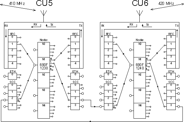
The necessary configuration:
The link output is routed to chosen SCC. The retranslation output from SCC is routed to the node.
The protocol MARS-A is configured on the respective node.
The way to the own address is written in the routing tables, see the description in the Routing 1.
The serial channels of both CUs are connected by the three-wire link (RX,TX,GND). The RX clamp on one CU is connected to the TX clamp on the others, so called crossed line.
The example of configuration CU5:
Nodes:
                                 retab
Nid|address |M | u   s | L   N |l w n g H|sTO Err  Cent vTO hTO
(0) 004AE97E     -  S00| -  R00|0 0 0 0 -| 15 SERV  OFF 304  30
(1) 690F1230    S00 S00|S02 R01|1 0 0 0 -| 15 SERV  OFF 304  30
(2) 00000000    S01 S00| -  R02|0 0 0 0 -| 15 SERV  OFF 304  30
(3) 00000000    S02 S00| -  R03|0 0 0 0 -| 15 SERV  OFF 304  30
(4) 00000000    S03 S00| -  R04|0 0 0 0 -| 15 SERV  OFF 304  30


Channel to Node Interface:
    retranslation     |   user+service             lim
 id N  A t          m | N  A t Base     m  sec brc S   e
(0) 0   NO AR         | 1   NO AR          usr OFF NONE
(1) 0   NO AR         | 2 MASK 00000000/08 usr OFF NONE
(2) 1   NO AR         | 1 MASK 00000000/08 usr OFF NONE
(3) 0   NO AR         | 0 MASK 00000000/08 usr OFF NONE


Local retab. No 1
40 to:30
The example of configuration CU6:
Nodes:
                                 retab
Nid|address |M | u   s | L   N |l w n g H|sTO Err  Cent vTO hTO
(0) 0049B897     -  S00| -  R00|0 0 0 0 -| 15 SERV  OFF 304  30
(1) 690F1240    S00 S00|S03 R01|1 0 0 0 -| 15 SERV  OFF 304  30
(2) 00000000    S01 S00| -  R02|0 0 0 0 -| 15 SERV  OFF 304  30
(3) 00000000    S02 S00| -  R03|0 0 0 0 -| 15 SERV  OFF 304  30
(4) 00000000    S03 S00| -  R04|0 0 0 0 -| 15 SERV  OFF 304  30


Channel to Node Interface:
    retranslation     |   user                     lim
 id N  A t          m | N  A t Base     m  sec brc S   e
(0) 0   NO AR         | 1 MASK 00000000/08 ON  OFF NONE
(1) 0   NO AR         | 2 MASK 00000000/08 ON  OFF NONE
(2) 1   NO AR         | 1   NO AR          ON  OFF NONE
(3) 0   NO AR         | 0 MASK 00000000/08 ON  OFF NONE


Local retab. No 1
30 to:40
The next response after sending of command ! is valid for the simple case, when the Setr is connected to CU5 and the CU6 is called:
690F1240h>!

u S00   690F1230    S02
  S03   690F1240   serd

 serd   690F1240    S03
  S02   690F1230  u S00
690F1240h>
An example with the serial line and with the addresses containing two different wide items.
The record of packet passing is contained in its left column. The entry DQ/RSS appears when the packet arrived through radio channel or the marking of serial channel, when the packet arrived by serial channel. In the right column is the marking of channel through which the packet left the node.
u S00   69802001    R01
30/ 56  69802002    S02
  S03   69802005    R01
25/ 46  6980300A   serd

 serd   6980300A    R01
27/ 42  69802005    S03
  S02   69802002    R01
30/ 56  69802001  u S00
6980300Ah>
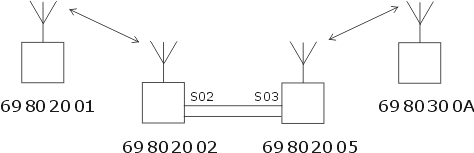
The comment to the content of the routing tables:
Tables in the node 69802001:
it is not necessary to route packets to node
69802001the routes from node
69802005, which is behind the serial link (so called “behind wires”), to the nodes69802005and6980300ALocal retab. No 1 05 to:02the route to node 6980300A will be looked for in the wide table, because the address
6980300Adiffers from the own one in the wide part:Wide retab. No 1 30to:2002
Tables in the node 69802002:
it is not necessary to route packets to node
69802002because their addresses are different in local part only and there is a direct radio connection.the way to the node
69802005is routed to69802002, the record is:Local retab. No 1 05 to:02the route to node
6980300A, whose address is different in the wide part, will be looked for in the wide table:Wide retab. No 1 30to:2002
Tables in the node 69802005:
the routes to the nodes
69802001and69802002are identical to that of the input to the wire link, so the routess in the local table are routed to own address:Local retab. No 1 01 to:05 02 to:05the route to the node
6980300Ais looked for in the wide table:Wide retab. No 1 30to:300A
Tables in the node 6980300A:
all nodes to which we will route the packets are lying in other wide than
30, so routes in wide table is required. Since all other nodes are lying in a common wide,20, only one route suffices:Wide retab. No 1 20to:2005
After this practice of routing we give again the description of process how the packet is going through the node completed with more details.