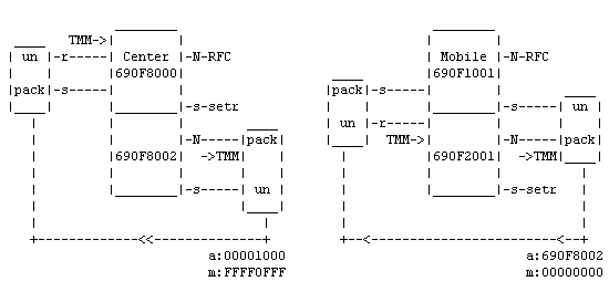
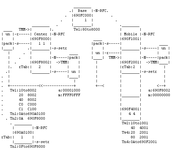
Tunnel MORSE-MORSE (TMM) is configured using the “Network Agent” (NAG) channel. This channel behaves in a similar way to the SCC from the point of view of configuration, however, it doesn’t have a physical output. After entering the NAG the packet is suitably modified and then sent via one of its “retranslation” or “user+service” outputs to a node within its CU.
Function of the Network Agent:
If a packet arrives to NAG from a node from the network output N it is fully packed into a service packet and given a new address.
Address dst is derived from the original dst address. Where there are “1” bits in the “GPe0ptm” mask the original dst address is maintained. In those bits where the mask is zero its bits are replaced with the respective values from the parameter addr. “GPe0pta”.
Address src is taken from the node which the “service” output NAG is connected to.
A packet set up in such a way is a “service” type packet, i.e. 12 or 92.
Service output NAG is connected to a suitable node, from which this packet then travels through the MORSE network to the dst address.
The following example was monitored in the CU according to the diagram shown on the left below:
Monitoring: source 690F8000|3.
CNI mon     |toa      frm     |dst      src     |          size|TT N
16:05:15.618|690F2001 690F8002|690F2001 690A0100|G00I    IN    2N09 1dat
AAAA
16:05:15.619|                 |690F1001 690F8000|G00I   OUT   12| 92 5serv
0129 690F 2001 690A 0100 AAAA
In the target node the packet is separated from the other “user” packets and continues via the “service” output to NAG. Here the original routing packet is unpacked from the service packet and is sent from the NAG output “ret” to a suitable node. From here it continues through the MORSE network in the standard manner.
The example was monitored in the CU according to the diagram on the right:
16:05:12.850|                 |690F1001 690F8000|G00I    IN   12|_92 5serv
0129 690F 2001 690A 0100 AAAA
16:05:12.850|690F1001 690F8000|690F2001 690A0100|G00I   OUT    2n09 1dat
AAAA

Example of the composition of the NAG packet: 0129 690F 2001
690A 0100 AAAA
| 0129 | header |
| 690F 2001 | dst address of original packet |
| 690A 0100 | src address of original packet |
| AAAA | data of original packet |
NAG Parameters:
From the Main menu using command GPe:
Nag:
 id |typ|subt|  addr |  mask  |
(0) 0001 0000 00001000 FFFF0FFF
(1) 0000 0000 00000000 00000000

de(f)ault (r)ead (w)rite
(I)nit (S)ync
(q)uit
>>
Select either of the two NAG and insert type TMM:
Ott
Return to the menu GPe and insert parameters:
Opt
Tunnel Morse-Morse parameters:
(s)ubt:0000
(a)ddr:00001000
(m)ask:FFFF0FFF
(q)uit
>>
Meaning of parameters:
| (m)ask | denotes which parts of the dst address will be taken to service packet address |
| (a)ddr | determines what left out parts will be replaced with |
| (s)ubt | reserve field |
The mobile network is capable of transferring packets between the Center and Mobile. The route, however, cannot be extended using standard routing procedures on either the Center side or Mobile side. In these cases we have to make use of the Network Agent and configure the Tunnel Morse-Morse through the mobile network. The configuration example follows on from the previous example of the mobile connection and is supplemented with the TMM configuration.
Passage of a packet from the supervisory center 690A0100 through tunnel TMM to node
690F4001 in the Mobile and
back:
u S02   690A0100    R01
31/ 68  690F8000     -
   -    690F8002    G00
  G00   690F2001     -
   -    690F4001   serd

 serd   690F4001     -
   -    690F2001    G00
  G00   690F8000    R01
30/ 75  690A0100  u S02
690F4001h>
The packet passes through the section from 690A0100 to 690F8002 through the use of routing
tables. Here it enters the tunnel, through which it is transferred as
the service packet over the mobile section. This part of the route is
not displayed in listing; it behaves as an inserted block. It then
continues again from 690F2001 to 690F4001 according to the routing
tables.

Notes on configuration:
An auxiliary node whose network output is directed towards NAG is added in the Center and in the Mobile. This node is the beginning of the tunnel.
The node at the beginning of the tunnel does not have routing tables for the direction “to the tunnel” which is why its sends all packets to its output “N” and thus to NAG. A routing packet which arrives at the tunnel in this way is packed in NAG (marked as “pack”). The packed packet then leaves NAG as a service packet and the output is again marked as “pack”.
The mask and address in menu
GPe0ptare inserted in such a way that NAG creates a dst address directed at a node with output “s” connected to the opposite NAG.In the Center the 4th character of the address from the right is replaced with
1, and the others remain the same. The three lower characters of the address determine the Mobile; the 4th character distinguishes the other nodes connected to this mobile. As an example, the following addresses are used in the Mobiles:Mobile 1 Mobile 2 Mobile 3 Mobile 4 690F1001 690F1002 690F1003 690F1004 690F2001 690F2002 690F2003 690F2004 690F4001 690F4002 690F4003 690F4004The complete address 690F8002, at which tunnels of all Mobiles end, is inserted into the dst address in the Mobile.
Nodes at which the tunnel ends are supplied with routing tables for distribution of routing packets which arrived from the tunnel. For node
690F2001this is Tw2 and for node690F8002it is Tn2.Other routing tables serve for sending packets to the beginning of the tunnel. For node
690F4001they are Tw4 and Tn4, for node 690F8000 fields 10,20,40 in Tw1.