| Note | |
|---|---|
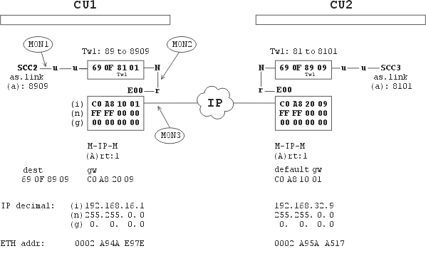
In next diagrams there is used the symbolism derived from chapter Communication Unit. For example the node 690F8101 in next picture is connected in menu Ne with it’s net output N to the channel ETH0 and the channel ETH0 is connected in menu EIe with it’s retranslation output r to the node 690F8101. |
Connection of CU via ETH
The connection of two MR400 by Ethernet link is used for the example of the M-IP-M mode.
The packet AAAA was received in CU1 by SCC2 port and was sent by Ethernet link to CU2. The monitoring in MON1 to MON3 points:
>>
     ...MON1...
CNI mon     |toa      frm     |dst      src     |          size|TT N
13:05:04.588|                 |00008909 00008101|S02I   OUT    2||89 0user
AAAA

     ...MON2...
13:05:04.588|690F8909 690F8101|690F8909 690F8101|E00I    IN    2N89 2dat
AAAA

     ...MON3...
13:05:04.588 rsi:68 tx|0002A95AA517 |0002A94AE97E | IP/UDP/MOR/RET/DAT
0002 A95A A517 0002 A94A E97E 0800 4500 0036 0072 4000 4011 88EA C0A8 1001
C0A8 2009 22B8 22B8 0022 EF70 D200 1391 690F 8909 690F 8101 0A89 690F 8909
690F 8101 AAAA C654

13:05:04.589 rsi:58 rx|0002A94AE97E |0002A95AA517 | IP/UDP/MOR/RET/CTL/ACK
0002 A94A E97E 0002 A95A A517 0800 4500 002C 000B 4000 4011 895B C0A8 2009
C0A8 1001 22B8 22B8 0018 28D0 C100 1391 D200 690F 8101 690F 8909 5D66
Comment:
The packet AAAA was received by SCC2 port with async.link protocol, was equipped by destination address 00008909 and was sent to the node 690F8101, see MON1.
Morse packet with address “to” 690F8909 is sent by “net” output to the channel E00, see MON2.
The packet is proceed according to M-IP-M. In the table (A)rt1 which is assigned to IP-M-IP mode there is the address IP destination C0A82009 found according to address “to” 690F8909.
IP destination is in range (n)et mask FFFF0000 equal to the own IP address C0A81001, that is why the packet is sent to IP destination. The packet goes from the eth.address 0002A94AE97E to 0002A95AA517, from IP address C0A81001 to C0A82009, see MON3.
In CU2 there is generated the asknowledge IP/UDP/MOR/RET/CTL/ACK and is sent back to CU1.
The packet receiver E00 in CU2 removes the IP head and sends the packet through retranslation output to the node. In this way is finished the delivery to the MORSE address “to” and the packet can continue according to MORSE routing.
Notes:
If conformity is not found in point 4) the packet is sent to the IP address given in parameter (g)ateway. For example, after changing (n)et mask in CU1 to value FFFFFF00 it is necessary to amend (g)ateway to C0A82009, in order to achieve a connection. This procedure is used for differentiating between packets directed to the local IP network and those to remote networks.
By selecting table Art in menu EPe0t one or more of the selected modes (M-IP-M, IP-M-IP or MAS) are activated. The Art Tables extent is limited. The tables Art1 to Art4 together can contain at the most 252 items. It is recommended use less then a 100 items in one table.
It is possible to use
default gwin the Art table in the normal manner for addresses which are not contained in the table, see CU2.Processing of addresses therefore proceeds as follows :
Using MORSE routing the address
tois found for the packet with the help of rTabUpon entering the ETH channel the destination IP address is found
by masking, see M-IP-M example 2
or in the Art table
or from default gw it Art table
According to
(n)et maskthe packet is sent to the above-mentioned IP address or to(g)atewayAfter reaching the destination IP address the IP header is removed from the packet and the packet is transferred to the node with MORSE address
toand continues through the MORSE network
After an idle period longer than is set by parameter
(A)RP ttlin menuEPe0Pan exchange of ARP packets takes place first and monitoring then looks as follows:
>>
14:30:20.089|                 |00008909 00008101|S02I   OUT    2||89 0user
AAAA
14:30:20.089|690F8909 690F8101|690F8909 690F8101|E00I    IN    2N89 3dat
AAAA
14:30:20.090 rsi:60 tx|FFFFFFFFFFFF |0002A94AE97E | ARP/REQ
FFFF FFFF FFFF 0002 A94A E97E 0806 0001 0800 0604 0001 0002 A94A E97E
C0A8 1001 0000 0000 0000 C0A8 2009 D3DC E2DB DD64 4E75 44AA A704 B917
F327 1537
14:30:20.090 rsi:68 rx|0002A94AE97E |0002A95AA517 | ARP/REP
0002 A94A E97E 0002 A95A A517 0806 0001 0800 0604 0002 0002 A95A A517
C0A8 2009 0002 A94A E97E C0A8 1001 D3DC E2DB DD64 4E75 44AA A704 B917
F327 1537 BDE4 7A14 85D2 5B34
14:30:20.090 rsi:68 tx|0002A95AA517 |0002A94AE97E | IP/UDP/MOR/RET/DAT
0002 A95A A517 0002 A94A E97E 0800 4500 0036 0073 4000 4011 88E9 C0A8 1001
C0A8 2009 22B8 22B8 0022 8D3C D200 1392 690F 8909 690F 8101 0B89 690F 8909
690F 8101 AAAA 2788
14:30:20.090 rsi:58 rx|0002A94AE97E |0002A95AA517 | IP/UDP/MOR/RET/CTL/ACK
0002 A94A E97E 0002 A95A A517 0800 4500 002C 000C 4000 4011 895A C0A8 2009
C0A8 1001 22B8 22B8 0018 979C C100 1392 D200 690F 8101 690F 8909 EE98
The more detailed description is in the paragraph Ethernet of document MORSE Firmware.
CU connected to ETH and RFC channels
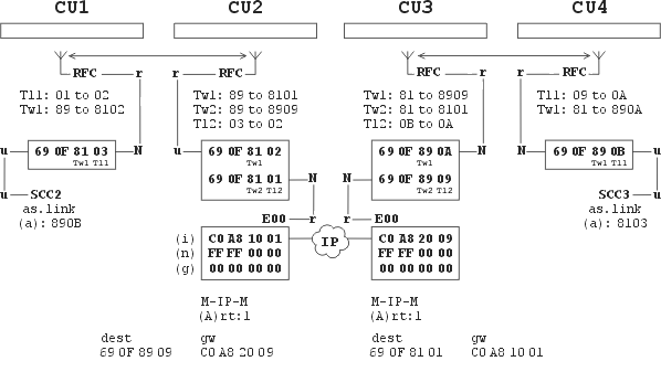
In mode M-IP-M the network output of the node is connected to channel ETH0. For generation of the connecting radio route we use another node whose network output (N) is connected to channel RFC. The route of the packet through both nodes is defined in the routing table. In the following example the route between four CUs is led through channels radio, ethernet and radio:
The packet passes from CU1 to CU4 and back as follows:
u S00   690F8103    R01
28/ 66  690F8102     -
   -    690F8101    E00
  E00   690F8909     -
   -    690F890A    R01
29/ 67  690F890B   serd

 serd   690F890B    R01
30/ 68  690F890A     -
   -    690F8909    E00
  E00   690F8101     -
   -    690F8102    R01
30/ 69  690F8103  u S00
690F890Bh>
An example of monitoring in CU2. The packet is sent from CU1 to CU4 and is monitored on entering CU2 via the radio channel and between node and ETH channel in CU2 :
RF mon      |toa      frm     |dst      src     |lNo!DQ!RSS size|TT N
06:47:51.332|690F8102 690F8103|690F890B 690F8103|029*28* 66    2*89 1dat
AAAA
CNI mon     |toa      frm     |dst      src     |          size|TT N
06:47:51.332|690F8909 690F8101|690F890B 690F8103|E00I    IN    2N89 1dat
AAAA
Address translating by mask:
The address of IP destination is sought in table Art according to MORSE address “to”. If these addresses are suitably selected it is possible to use mask conversion of addresses instead of using Art. Example 2 is with modified IP addresses:
      CU2             CU3
   690F8101        690F8909
          |               |
   C0A80101---IP---C0A80909
   FFFFF000        FFFFF000
ETH parameter settings in CU2 and CU3:
M-IP-M:
  (A)rt:0; write (E)nable:ON
  (b)ase:690F8000  MAS(K):00000FFF  s(h)ift:0000 ->set Security off!
  (r)epeats:0000  Sec(u)rity:OFF (t)imeout:0  (p)roxy timeout:0s
  (f)rag size:1400bytes  (g)lue (append) up to:0packets
When using a mask:
(b)ase and opposite MORSE address are the same in those parts where the MAS(K) has zeroes
IP addresses of CU1 and CU2 are the same in those parts where the MAS(K) has zeroes
MORSE address and IP address of the CU are the same in those parts where the MAS(K) has ones
Sec(u)rity:OFF – conversion over Ethernet takes place without confirmation, fragmentation OFF, recomended (f)rag size:1400, e.g. the content of routing table does not go through the network at (f)rag size:400
table Art is not used, if masking is not possible then takes place the Art conversion
number of addresses unlimited, the IP channel capacity is well exploited
Characteristics of Art translating:
Sec(u)rity:OFF – unsecured transfer, fragmentation OFF, (f)rag size:1400 recomended
Sec(u)rity:ON – secured transfer, fragmentation according (f)rag size:200 to 1400
possible around 100 addresses at the most
worse utilization of IP channel

