The Ethernet channel in the MORSE CU offers 3 modes of operation, M-IP-M, IP-M-IP, MAS:
M-IP-M
The packet travelling through the MORSE network has a section going along the IP network inserted into its path. The packet has the following configuration:

Looking at the configuration of the MORSE network the IP section appears as one of the routing jumps between two nodes. Routing tables are compiled in the same way as if this section would be one of the radio jumps. The relationship with IP is configured in the Ethernet channel and Art tables in two CUs at the interface with the IP part.
IP-M-IP
The packet in the IP network has a section going along the MORSE network inserted into its path. Packet configuration:

For the MORSE network the event begins with receipt of the packet from the user output of the Ethernet channel to the node and ends with transfer of the packet through the user output of the last node to the Ethernet channel. The relationships with IP are contained in the Ethernet channel and Art tables in the end CU.
MAS
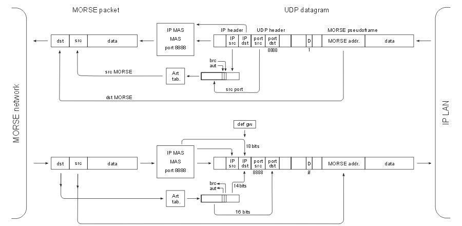
The MORSE Application Server is designed for connecting an application running on the LAN network with end points lying in the MORSE network. MAS replaces the IP header with the MORSE header and vice versa:

If the application in the LAN network sends a UDP datagram to any of the terminals in the MORSE network then the MORSE destination address is contained in the data of this datagram and is used by MAS to compile the MORSE header. The “source” MORSE address as the second main parameter of the MORSE header is derived from the senders IP address and port by means of Art. In a similar manner the IP destination address and port number are derived from the MORSE destination address when processing the incoming packet from the MORSE network. The MORSE source address is then inserted into the MORSE pseudoframe in the data part of the UDP datagram.
A description of these modes is given in the Ethernet chapter of MORSE firmware documentation.
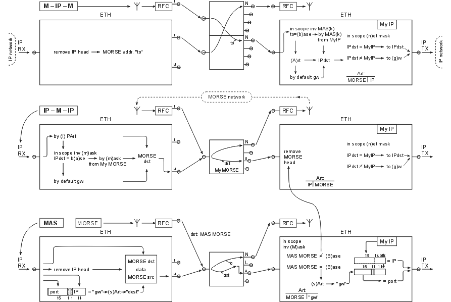
The following diagram Ethernet channel modes provides a clear portrayal of the principles of configuration for these three modes. It does not compensate for a detailed description. In order to place all important information into one picture the following symbols and simplifications were used:
At the top there is the configuration for mode M-IP-M, in the middle for IP-M-IP, and at the bottom for MAS.
The packet´s path begins with the mode symbol, for example : M-IP-M
Symbology derived from the Communication unit chapter is used here. The squares in the middle represent nodes in the CU, rectangles are ETH channels in the CU, enlarged so that the respective operations can be marked inside them.
Each picture illustrates two CUs. For example, in the upper picture the packet arrives from the MORSE network over the RFC channel via two nodes to the ETH channel. It then gets to the second CU through the “IP network”, which continues on the left side of the picture, and from here it continues via ETH, nodes, and RFC to the MORSE network. The right ETH contains the operations when passing from the node to LAN, and on the left when passing from LAN to the node.
Description of the function of individual modes
M-IP-M
A packet arrives from the MORSE network. It enters the first node and according to routing continues to the second whose network output N is connected to the ETH channel. Routing in the second node determines the address of the following node to, with which the packet enters the ETH channel.
Here IPdst,which appertains to the MORSE ETH channel on the second side of LAN, is found in the Art table according to the to address. A UDP datagram is created which contains the original MORSE packet. If in the range of mask (n)et mask the IPdst is the same as the actual IP address of the ETH channel MyIP, then the UDP datagram is sent to IPdst. If it is not the same it is sent to the (g)ateway address.
After passing through the IP network the UDP datagram enters the ETH channel with address IPdst (left side of the diagram). After removing the IP header the original MORSE routing packet appears which passes through the retranslation output r from the ETH channel to the node with address to. It continues according to routing to the neighbouring node, through its output N to the RFC channel and on through the MORSE network.
IP-M-IP
A datagram arrives from the IP network to the ETH channel.
According to the IPdst address the
MORSE destination address dst is created in one of three
ways:
– conversion according to Art table EPe0tI
– if IPdst is
not found in the table and if IPdst is the same as base EPe0ta in the
range of the inverse mask EPe0tm, then
the MORSE dst is made up from MyMORSE and IPdst according to
mask EPe0tm
– if none of these procedures are possible
default gw from Art table EPe0tI is
used
The resulting address MORSE dst is used for compiling a user type MORSE packet which is transferred to the node. From there the packet continues through the MORSE network according to routing rules. Once the packet arrives at the node with the MORSE address dst it is transferred from this node through the user output to the ETH channel.
Here the MORSE header is removed leaving the original IP datagram. This is sent to the IP network in the normal manner, i.e. to address IPdest or to address EPe0g, i.e. (g)ateway
MAS
A) a UDP frame arrives from the IP network. An item labelled here as “gw” is compiled from its parts port src, the lower part of address IP src and two other bits. The MORSE src address which appertains to the IP application which sent the UDP frame is found in the Art table EPe0ts according to this. MAS compiles a MORSE packet supplied with this MORSE src address. The MORSE dst address and transferred data are taken from the incoming UDP frame.
This user type packet is sent to the node and continues from there through the MORSE network to the destination CU.
B) A packet arriving from the MORSE network can have a destination address the same as the MAS MORSE and then it is sent through the user output to the ETH channel. Often Multiaddressing is used, whereby the incoming packet, which has a different address to the address of the node, is directed by routing to the link output. From here it is redirected by parameter Ne1MLn to the user output and to ETH.
In the ETH channel the destination address of the MAS MORSE incoming packet is compared with base EPe0tB. If it is the same in the range of mask EPe0tM the packet is processed in MAS, otherwise it continues in mode IP-M-IP. According to the MAS MORSE address item “gw” is found in Art table EPe0ts. A UDP frame is compiled from this item, the actual IP address, and data from the incoming packet, and is sent to the connected LAN.
Conversion of UDP datagram addresses to MORSE and back is clearly illustrated in the diagram Conversion of addresses for UDP. A more detailed description of the UDP datagram is contained in article Chapter 6, Format of UDP datagram IPGW for Morse.
Mode selection
Channel ETH can operate in two or three modes at the same time. For activation of a mode it is necessary to insert a non-zero Art table number in the EPe0t menu.
Diagrams are available separately in PDF format: Ethernet channel modes, Conversion of addresses for UDP.

